7DSH#'ULYHV
EXB-8205
EXB-8505
8mm Cartridge Tape Subsystems
the property of EXABYTE Corporation. No part of this document may be reproduced, transmitted, transcribed, stored in a retrieval system, or translated into any language or computer language in any form or by any means, electronic, mechanical, magnetic, optical, chemical, manual, or otherwise, without the express written permission of EXABYTE Corporation, 1685 38th Street, Boulder, Colorado 80301.
Disclaimer
EXABYTE Corporation makes no representation or
warranties with respect to the contents of this document and specifically disclaims any implied warranties of
merchantability or fitness for any particular purpose. Further, EXABYTE Corporation reserves the right to revise this publication without obligation to notify any person or organization of such revision or changes.
Trademark Notices
EXABYTE is a registered trademark and EXATAPE is a trademark of EXABYTE Corporation.
Revision History
Revision Date
000 October 1992
Product Warranty Caution
The EXB-8205 and EXB-8505 8mm Cartridge Tape
Subsystems (CTSs) are warranted to be free from defects in materials, parts, and workmanship and will conform to the current product specifications upon delivery. For the specific details of your warranty, refer to your sales contract or contact the company from which the EXB-8205 or EXB-8505 was purchased.
The warranty for the EXB-8205 and EXB-8505 shall not apply to failures caused by:
■ Physical abuse or use not consistent with the operating instructions or product specifications provided by EXABYTE’s personnel or agent for the applicable equipment.
■ Modifications by other than EXABYTE’s personnel or agent in any way other than those approved by EXABYTE, provided the warranty shall not be voided by the repair or replacement of parts or the attachment of items in the manner described in maintenance or installation instructions provided by EXABYTE.
■ Repair by other than EXABYTE’s personnel or agent in a manner contrary to the maintenance instructions
provided by EXABYTE.
■ Removal of the EXABYTE serial number tag.
■ Physical abuse due to improper packaging of returns.
CAUTION
Returning the EXB-8205 or EXB-8505 in unauthorized packaging may damage the unit and void the warranty. If you are returning the EXB-8205 or EXB-8505 for repair, package it in its original packaging (or in replacement packaging obtained from your vendor). Refer to the packing instructions in the EXB-8205 8mm Cartridge Tape Subsystem User’s Manual or the EXB-8505 8mm Cartridge Tape Subsystem User’s Manual.
Contents
About This Manual
ix
1 Before You Begin
1-1
Troubleshooting the CTS . . . 1-2 Static protection requirements for the troubleshooting environment . . . 1-2 Tools required for troubleshooting . . . 1-2 Troubleshooting guidelines . . . 1-3 Troubleshooting table . . . 1-4 Performing Maintenance Procedures . . . 1-11 Static protection requirements for the maintenance environment . . . . 1-12 Tools required for maintenance . . . 1-13 Maintenance guidelines . . . 1-14 Preparing the CTS for Operation After Maintenance . . . 1-15
2 Cleaning the CTS
2-1
Determining When the CTS Needs Cleaning . . . 2-2 Time-to-clean LED indication . . . 2-2 REQUEST SENSE (03h) command . . . 2-2 Using the 8mm Cleaning Cartridge . . . 2-3
3 Loading New Microcode from Tape
3-1
Creating a Microcode Update Tape . . . 3-2 Steps for making a microcode update tape . . . 3-2 Time required to make a microcode update tape . . . 3-5 Using a Microcode Update Tape . . . 3-6 Steps that occur during the microcode update process . . . 3-6 Time required to load code from tape . . . 3-9
4 Removing a Cartridge from the CTS
4-1
Replacing the SLD Card . . . 5-28 Do this first . . . 5-28 Procedure for removing the SLD card . . . 5-28 Procedure for replacing the SLD card . . . 5-30 Preparing the CTS for operation . . . 5-33 Replacing the VUA–SLD Flex Cable . . . 5-34 Do this first . . . 5-34 Procedure for removing the VUA–SLD flex cable . . . 5-34 Procedure for replacing the VUA–SLD flex cable . . . 5-35 Preparing the CTS for operation . . . 5-36 Replacing the Deck Subassembly . . . 5-37 Do this first . . . 5-37 Procedure for replacing the deck subassembly . . . 5-38 Preparing the CTS for operation . . . 5-43 Replacing the Door and Retainer . . . 5-44 Do this first . . . 5-44 Procedure for removing the door and retainer . . . 5-44 Procedure for replacing the door and retainer . . . 5-46 Preparing the CTS for operation . . . 5-48
About This Manual
This manual provides instructions for performing maintenance on the EXABYTE®EXB-8205 and EXB-8505 8mm Cartridge Tape Subsystems
(CTS). It explains how to clean the tape path, load microcode, remove a data cartridge from a nonfunctioning CTS, and replace field
replaceable units (FRUs).
Intended audience
This manual assists EXABYTE self-maintenance contract customers in the troubleshooting and maintenance of the CTS.
CAUTION
To perform the procedures in this manual, you must be a qualified service technician whose organization has a self-maintenance agreement with EXABYTE Corporation. If these steps are performed by an unqualified individual, the product warranty will be voided.
Contents of this manual
This manual contains the following information:
Chapter 1contains information about preparing for CTS maintenance, including required tools and equipment for troubleshooting and maintenance as well as approaches to maintenance.
Chapter 2contains instructions for cleaning the CTS’s tape path using an EXABYTE or EXABYTE-approved 8mm cleaning cartridge.
Chapter 3provides instructions for loading firmware to the CTS.
A glossary, index, and reader’s comment form are included at the back of this manual.
How to use this manual
Before performing any of the maintenance procedures in this manual, read Chapter 1. This chapter describes troubleshooting procedures that help you determine the maintenance procedures to perform; lists the required tools and equipment for troubleshooting and
maintenance; and lists the guidelines for protecting the CTS against electrostatic discharge when performing any of the procedures in this manual.
If you need to perform routine maintenance, such as cleaning the tape path or upgrading microcode, refer to Chapter 2 or Chapter 3 as appropriate. If you have determined that you need to replace a FRU, and you have received the new FRU from EXABYTE, refer to the section in Chapter 5 that describes how to replace the FRU and how to prepare the CTS for operation after you have replaced a FRU.
CAUTION
Conventions used in this manual
This manual uses special conventions to highlight action items, notes, important information, cautions, and warnings. The following shows the format and definitions of this text. Take special note of boxed text. Failure to follow cautions can result in equipment damage or personal injury!
➥
Text that is preceded by an arrow indicates an important actionthat you should perform before continuing.
Text in courier typeface indicates messages that appear on your computer screen when you are using CTS Monitor.
Note: Read notes for hints or suggestions about the topic or procedure being discussed.
Important
Read the information in Important boxes to learn convenient methods of following the procedure discussed in the text. Important messages help you to successfully complete or avoid additional steps in a procedure.
CAUTION
Read the information in Caution boxes to avoid damaging equipment. Caution messages help you to successfully complete a procedure and avoid a potentially damaging event.
tasks referred to in this manual.
EXB-8205 8mm Cartridge Tape Subsystem User’s Manual, 510701 EXB-8205 8mm Cartridge Tape Subsystem Product Specification,
510703
EXB-8505 8mm Cartridge Tape Subsystem User’s Manual, 510503 EXB-8505 8mm Cartridge Tape Subsystem Product Specification,
510504
EXPERT User’s Guide for the 8mm Cartridge Tape Subsystem, 510010 EXABYTE Monitor User’s Guide for the 8mm Cartridge Tape
1
Before You Begin
This chapter contains the following information: Troubleshooting the CTS
• Static protection requirements for the troubleshooting environment
• Tools and equipment required for troubleshooting
• Troubleshooting guidelines Maintaining the CTS
• Static protection requirements for the maintenance environment
• Tools and equipment required for maintenance
Troubleshooting the CTS
To determine which maintenance procedures you need to perform on your CTS, follow the steps in this section.
Static protection requirements for the troubleshooting
environment
The troubleshooting environment for the CTS must be free of conditions that could cause electrostatic discharge (ESD). To ensure that the environment is as free from ESD as possible, follow these static protection guidelines when performing troubleshooting procedures on the CTS:
Ensure that the power supply connected to the CTS is properly grounded.
Ensure that the personal computer used for EXPERT and Monitor software and for the SCSI bus is properly grounded.
CAUTION
Failure to use these static protection methods may cause severe damage to the CTS.
Tools required for troubleshooting
When performing troubleshooting procedures on the CTS, you need the following equipment:
EXABYTE EXPERT software (version 6.70 or later), EXPERT
User’s Guide for the 8mm Cartridge Tape Subsystem, and equipment
required to run EXPERT. EXPERT tests are designed to evaluate the performance of the CTS during specific types of operations. CTS Monitor software (version 12.54 or later), CTS Monitor User’s
For each CTS you want to test, one blank 15m EXATAPE data cartridge.
To order these tools for troubleshooting, contact your vendor.
Troubleshooting guidelines
When a problem arises with the CTS, test the CTS before performing any maintenance procedures to determine the problem and possible solutions. Follow these troubleshooting guidelines:
1.
Make sure the troubleshooting environment meets the static protection requirements listed on page 1-2. Failure to use these static protection methods may cause severe damage to the CTS.2.
Use a known good power supply for each CTS under test to verify operation and to eliminate any outside influences on the test. Verify that all power to the test area is clean and free of feedback or inductive spikes. Also verify that the power supply connector is making good contact.Power problems will typically cause a high percentage of rewrites or error correction code (ECC)—or extreme difficulty getting known good CTSs to pass the tests consistently.
3.
Run EXPERT software tests to help you determine specific problems with the CTS. Refer to the EXPERT User’s Guide for instructions.To ensure accuracy and consistency when testing a string of CTSs, start all CTSs at the same time and run them without interruption to completion.
4.
Try the test cartridges in two or three different CTSs to ensure that any failures reported by EXPERT are CTS-related rather than tape-related. If a media error occurs, repeat the test with a known good cartridge to verify that the failure is CTS-related.5.
After running EXPERT tests, refer to Table 1-1 in the next section to determine the maintenance procedures to perform.Troubleshooting table
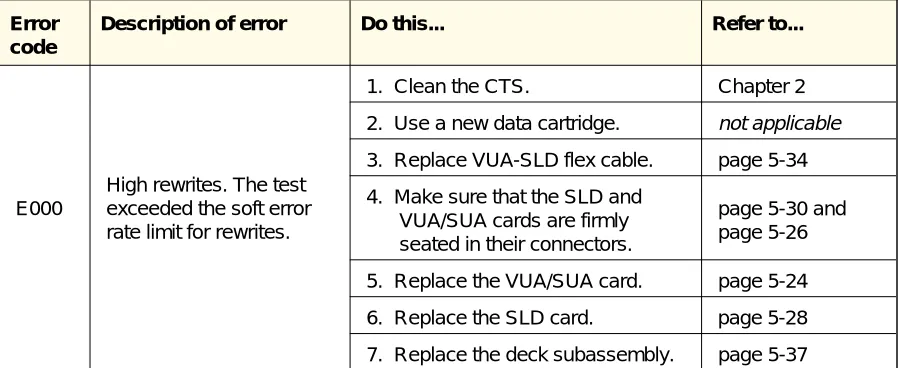
Table 1-1 contains information about CTS errors that you may encounter while running EXPERT tests. It includes a description of each error and the action to take for each error. Use Table 1-1 to determine the maintenance procedures you need to perform on your CTS, and then refer to the indicated chapter or page for instructions.
Note: For each error listed in Table 1-1, perform the steps in the Do
this...column one at a time. Proceed to the next step in this column only if the previous step does not correct the problem.
Error code
Description of error Do this... Refer to...
E000
High rewrites. The test exceeded the soft error rate limit for rewrites.
1. Clean the CTS. Chapter 2
2. Use a new data cartridge. not applicable 3. Replace VUA-SLD flex cable. page 5-34 4. Make sure that the SLD and
VUA/SUA cards are firmly seated in their connectors.
[image:17.612.73.522.417.601.2]page 5-30 and page 5-26 5. Replace the VUA/SUA card. page 5-24 6. Replace the SLD card. page 5-28 7. Replace the deck subassembly. page 5-37
Error code
Description of error Do this... Refer to...
E001
High ECC. The test exceeded the soft error rate limit for ECC (error correction code).
1. Clean the CTS. Chapter 2
2. Use a new data cartridge. not applicable 3. Replace VUA-SLD flex cable. page 5-34 4. Make sure that the SLD and
VUA/SUA cards are firmly seated in their connectors.
page 5-30 and page 5-26 5. Replace the VUA/SUA card. page 5-24 6. Replace the SLD card. page 5-28 7. Replace the deck subassembly. page 5-37
E002
High tracking. The test exceeded the soft error rate limit for tracking retries.
1. Clean the CTS. Chapter 2
2. Use a new data cartridge. not applicable 3. Replace VUA-SLD flex cable. page 5-34 4. Make sure that the SLD and
VUA/SUA cards are firmly seated in their connectors.
page 5-30 and page 5-26 5. Replace the VUA/SUA card. page 5-24 6. Replace the SLD card. page 5-28 7. Replace the deck subassembly. page 5-37
E003
High rereads. The test exceeded the soft error rate limit for rereads.
1. Clean the CTS. Chapter 2
2. Use a new data cartridge. not applicable 3. Replace VUA-SLD flex cable. page 5-34 4. Make sure that the SLD and
VUA/SUA cards are firmly seated in their connectors.
page 5-30 and page 5-26 5. Replace the VUA/SUA card. page 5-24 6. Replace the SLD card. page 5-28 7. Replace the deck subassembly. page 5-37
E012
Duplicate SCSI ID. Two or more CTSs are addressed to the same SCSI ID.
1. Make sure that you have
assigned a unique SCSI address to each device on your SCSI bus.
not applicable
2. Replace the SLD card. page 5-28
E013
I/O timeout. The CTS never reached the ready state for the test.
Replace the SLD card. page 5-28
Error code
Description of error Do this... Refer to...
E014
SCSI reset failure. The CTS never reset when you issued the reset command.
1. Make sure that you have
assigned a unique SCSI address to each device on your SCSI bus.
not applicable
2. Replace the SLD card. page 5-28 3. Replace the VUA/SUA card.
E015
Adaptec board fail. A SCSI command failed while attempting to execute.
1. Make sure that you have assigned a unique SCSI address to each device on your SCSI bus.
not applicable
2. Replace the SLD card. page 5-28
E016
SCSI inbound parity error. SCSI communication was interrupted.
1. Make sure that you have
assigned a unique SCSI address to each device on your SCSI bus.
not applicable
2. Replace the SLD card. page 5-28
E017
Buffer miscompare. Data in the buffer did not match the expected data to the host (initiator).
Replace the SLD card. page 5-28
E027
Byte 2 filemark error (see the Extended Sense Bytes of the REQUEST SENSE command in the user’s manual for your CTS).
1. Replace the SLD card. page 5-28 2. Replace the VUA/SUA card. page 5-24 3. Replace deck subassembly. page 5-37
E032
Not ready. The CTS cannot be accessed through the SCSI bus.
1. Make sure that you have
assigned a unique SCSI address to each device on your SCSI bus.
not applicable
2. Replace the SLD card. page 5-28
E033
Medium error. One block of data was
unsuccessfully written on tape 10 times or 40 blocks in a row were
unsuccessfully written.
1. Clean the CTS. Chapter 2
2. Use a new data cartridge. not applicable 3. Replace the VUA-SLD flex cable. page 5-34 4. Make sure that the SLD and
VUA/SUA cards are firmly seated in their connectors.
page 5-30 and page 5-26 5. Replace the VUA/SUA card. page 5-24 6. Replace the SLD card. page 5-28 7. Replace the deck subassembly. page 5-37 Hardware error. The CTS
Error code
Description of error Do this... Refer to...
E035
Illegal request. A SCSI command was issued that was logically or
structurally incorrect.
1. Make sure your EXPERT setup is correct.
EXPERT User’s Guide
2. Replace the SLD card. page 5-28 3. Replace the deck subassembly. page 5-37
E036
Unit attention. Either the data cartridge was changed or a reset performed on the CTS since the last command or power-up.
1. Make sure that you have
assigned a unique SCSI address to each device on your SCSI bus.
not applicable
2. Replace the SLD card. page 5-28 3. Replace the deck subassembly. page 5-37
E037
Data protect failure. A write command was attempted with the write protect tab in the on position.
If you want to write data to that cartridge, put the write protect tab in the off position.
not applicable
E051 Selection time out.
1. Make sure that you have
assigned a unique SCSI address to each device on your SCSI bus.
not applicable
2. Replace the SLD card. page 5-28
E05C SCSI error.
1. Make sure that you have
assigned a unique SCSI address to each device on your SCSI bus.
not applicable
2. Replace the SLD card. page 5-28
E201
Format error. The data formatter detected an error.
1. Replace the SLD card. page 5-28 2. Replace the deck subassembly. page 5-37
E202
Servo system error. The servo system detected a hardware error.
1. Replace deck subassembly. page 5-37 2. Replace the SLD card. page 5-28
E208
Formatter underrun. The data formatter detected a data flow underrun.
Replace SLD card. page 5-28
E910
Medium error. One block of data was
unsuccessfully written on tape 10 times or 40 blocks in a row were
unsuccessfully written.
1. Clean the CTS. Chapter 2
2. Use a new data cartridge. not applicable 3. Replace the VUA-SLD flex cable. page 5-34 4. Make sure that the SLD and
VUA/SUA cards are firmly seated in their connectors.
page 5-30 and page 5-26 5. Replace VUA card. page 5-24
Error code
Description of error Do this... Refer to...
E920
Formatter buffer parity error. The data formatter detected an internal data buffer parity error.
Replace the SLD card. page 5-28
E980
Power fail. The CTS has been reset or powered on since the last status was sent to the host (initiator).
1. Make sure that the power cable is firmly connected to the CTS and the power source.
not applicable
2. Make sure that the VUA-SLD flex cable is firmly connected to the VUA/SUA and SLD cards.
page 5-35
3. Make sure that the VUA/SUA and SLD cards are firmly seated in their connectors.
page 5-30 and page 5-26 4. Replace the SLD card. page 5-28 5. Replace the deck subassembly. page 5-37
S101
Load/unload problem. The servo system has
detected a load motor failure.
1. Make sure that the front bezel is
seated correctly. page 5-3
2. Make sure that the front panel is
seated correctly. page 5-6
3. Make sure that the door is
installed correctly. page 5-46 4. Replace the deck subassembly. page 5-37
S102
Mode control failed. The servo system has detected a mode motor failure.
Replace the deck subassembly. page 5-37
S104 MCU RAM trap failed 1. Replace the SLD card. page 5-28 2. Replace the deck subassembly. page 5-37
E107 EEPROM firmware problem
1. Reload the EEPROM code. Make sure you are loading the correct version of code.
Chapter 3
2. Replace the SLD card. page 5-28 S108 EPROM checksum failure. Replace the deck subassembly. page 5-37
S110
Command reject. The servo system rejected a command from the microprocessor.
Error code
Description of error Do this... Refer to...
S120
Capstan motion. The servo system has
detected that the capstan motion does not meet specification.
1. Make sure that the power cable is firmly connected to the CTS and the power source.
not applicable
2. Make sure that the VUA-SLD flex cable is firmly connected to the VUA/SUA and SLD cards.
page 5-35
3. Make sure that the VUA/SUA and SLD cards are firmly seated in their connectors.
page 5-30 and page 5-26 4. Replace the deck subassembly. page 5-37
S140
Drum motion problem. The servo system has detected that the drum motion does not meet specification.
1. Make sure that the power cable is firmly connected to the CTS and the power source.
not applicable
2. Make sure that the VUA-SLD flex cable is firmly connected to the VUA/SUA and SLD cards.
page 5-35
3. Make sure that the VUA/SUA and SLD cards are firmly seated in their connectors.
page 5-30 and page 5-26 4. Replace the deck subassembly. page 5-37
S201
BOT sensor failure. The servo system does not detect the beginning of tape when expected.
Replace the deck subassembly. page 5-37
S202
EOT sensor failure. The servo system does not detect the end of tape when expected.
Replace the deck subassembly. page 5-37
S204
No capstan tach. The servo system has
detected that the capstan is not moving.
1. Make sure that the power cable is firmly connected to the CTS and the power source.
not applicable
2. Make sure that the VUA-SLD flex cable is firmly connected to the VUA/SUA and SLD cards.
page 5-35
3. Make sure that the VUA/SUA and SLD cards are firmly seated in their connectors.
page 5-30 and page 5-26 4. Replace the deck subassembly. page 5-37
Error code
Description of error Do this... Refer to...
S208
No supply tach. The servo system has detected that the supply reel is not moving.
1. Make sure that the power cable is firmly connected to the CTS and the power source.
not applicable
2. Make sure that the VUA-SLD flex cable is firmly connected to the VUA/SUA and SLD cards.
page 5-35
3. Make sure that the VUA/SUA and SLD cards are firmly seated in their connectors.
page 5-30 and page 5-26 4. Replace the deck subassembly. page 5-37
S210
No drum tach. The servo system has detected that the drum is not moving.
1. Make sure that the power cable is firmly connected to the CTS and the power source.
not applicable
2. Make sure that the VUA-SLD flex cable is firmly connected to the VUA/SUA and SLD cards.
page 5-35
3. Make sure that the VUA/SUA and SLD cards are firmly seated in their connectors.
Performing Maintenance Procedures
Before performing maintenance procedures, use the troubleshooting guidelines in the previous section to help you determine the
maintenance procedures to perform.
You can perform these procedures on the CTS: Cleaning the tape path
Loading new microcode from tape
Removing a cartridge from a nonfunctioning CTS
You can also replace the following field replaceable units (FRUs): Chassis panels
Deck subassembly Door and retainer Front bezel SLD card VUA card
VUA/SLD flex cable
Any other maintenance procedures must be performed by EXABYTE.
Static protection requirements for the maintenance
environment
The maintenance environment for the CTS must be free of conditions that could cause electrostatic discharge (ESD). To ensure that the environment is as free from ESD as possible, follow these static protection guidelines when performing maintenance procedures on the CTS:
Place a static protection mat on the work surface. Use a 1-megohm resistor to ground the static protection mat.
Wear a static protection wrist band whenever you handle the CTS or CTS cards that have been removed from their antistatic bags. Connect the wrist band to the static protection mat or to other suitable ESD grounding.
Keep all cards in antistatic bags when not in use.
CAUTION
Tools required for maintenance
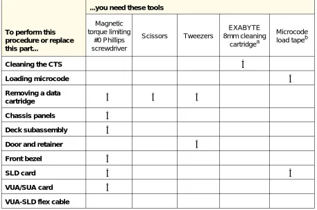
Refer to Table 1-2 to determine the tools you need to perform the maintenance procedures described in this manual. Also, a list of the tools needed for a procedure is provided at the beginning of the procedure.
To perform this procedure or replace this part...
...you need these tools
Magnetic torque limiting #0 Phillips screwdriver Scissors Tweezers EXABYTE 8mm cleaning cartridgea Microcode load tapeb
Cleaning the CTS ✔
Loading microcode ✔
Removing a data
cartridge ✔ ✔ ✔
Chassis panels ✔
Deck subassembly ✔
Door and retainer ✔
Front bezel ✔
SLD card ✔ ✔
VUA/SUA card ✔
VUA-SLD flex cable
aTo avoid damage to the CTS, you must use an EXABYTE or EXABYTE-approved 8mm cleaning
cartridge.
bSee Chapter 3 for instructions for making a microcode load tape.
CAUTION
[image:26.612.88.545.217.520.2]Use a magnetic #0 Phillips screwdriver when replacing CTS parts. The CTS contains very small (M2×0.02×3.0) screws. If these screws are dropped through the vent holes in the CTS, they may cause serious damage.
Table 1-2 Tools needed to perform maintenance procedures
Note: You can order replacement screws from EXABYTE. See the
EXB-8205 and EXB-8505 8mm Cartridge Tape Subsystems Illustrated Parts Catalog.
Maintenance guidelines
Once you have determined which FRU needs to be replaced, follow the appropriate instructions in Chapter 5 to replace the FRU. Before you start, perform the following preliminary maintenance procedures:
1.
Make sure the current operation has completed and that tape motion has stopped. Tape motion has stopped when the bottom LED stops blinking.2.
If necessary, unload the data cartridge by pressing the unload button or issuing a LOAD/UNLOAD (1Bh) command to the CTS.Note: If a data cartridge is loaded in a nonfunctioning CTS, refer to Chapter 4 for instructions on removing the data cartridge.
3.
Make sure the maintenance environment meets the static protection requirements listed on page 1-12.4.
Make sure that another device terminates the SCSI bus and that there is no activity on the bus. The middle LED stops flashing when there is no activity on the SCSI bus.5.
Disconnect the SCSI cable from the CTS.Note: If you plan to clean the CTS or load new microcode, do not perform the rest of these steps. Instead, refer to Chapter 2 (for cleaning) or Chapter 3 (for loading new microcode).
6.
Disconnect the power cable from the CTS.Preparing the CTS for Operation After
Maintenance
After performing each maintenance procedure, follow the instructions provided after each procedure to prepare the CTS for operation. These instructions indicate which procedures and EXPERT tests you should perform.
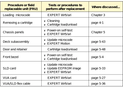
Table 1-3 lists the procedures and tests that you should perform after each maintenance procedure. For more details about the tests or procedures and the results you should expect, refer to the chapter for the maintenance procedure you are performing.
Procedure or field replaceable unit (FRU)
Tests or procedures to
perform after replacement Where discussed...
Loading microcode EXPERT WrtVari Chapter 3
Removing a cartridge ■ Cleaning
■ Cartridge load/unload page 4-1 Chassis panels ■ Power-on self-test
■ EXPERT WrtVari Chapter 5 Deck subassembly ■ Update microcode
■ EXPERT Motion page 5-43
Door and retainer Cartridge load/unload page 5-48 Front bezel ■ Power-on self-test
■ Cartridge load/unload page 5-4 SLD card
■ Update microcode ■ Update EEPROM image ■ EXPERT WrtVari
page 5-33
VUA card EXPERT WrtVari page 5-27
VUA/SLD flex cable EXPERT WrtVari page 5-36
For any of the EXPERT tests listed in this table, refer to the EXPERT
[image:28.612.145.538.316.596.2]User’s Guide for the 8mm Cartridge Tape Subsystem for more information.
Table 1-3 Tests and procedures to perform after maintenance
2
Cleaning the CTS
This chapter describes how to clean the CTS’s heads and tape path. The CTS’s heads and tape path should be cleaned on a regular basis. If you are experiencing write or read errors with your CTS, clean the CTS using the procedures described in this chapter before you perform any other maintenance procedures to see if cleaning corrects the problem.
The only cleaning material authorized for use with the CTS is an EXABYTE or EXABYTE-approved 8mm cleaning cartridge.
Important
You should clean the CTS’s heads and tape path after every 30 tape
motion hours. This cleaning frequency does not depend on the format in which you write and read data. However, if you are using the CTS in a particularly dirty environment, or if you operate it
infrequently, you may want to clean the CTS more often than every 30 tape motion hours. Cleaning the CTS helps ensure that it will perform according to its specifications.
The CTS keeps track of tape motion hours internally. You can access this information in either of the following ways.
Time-to-clean LED indication
When 30 tape motion hours have elapsed, the top and bottom LEDs will flash rapidly and the middle LED will flash irregularly,
depending on SCSI bus activity. For best results, clean the CTS as soon as possible after the LEDs begin flashing.
REQUEST SENSE (03h) command
Using the 8mm Cleaning Cartridge
CAUTION
To prevent contamination of the CTS and damage to the heads, do not use the cleaning cartridge for more than the number of cleaning cycles specified on the cartridge label. Discard the cleaning cartridge after you have used it for the specified number of cleaning cycles. Do not attempt to rewind the material in the cleaning cartridge and reuse it.
To use the cleaning cartridge, follow these steps:
1.
Apply power to the CTS. When the power-on self-test is complete, press the unload button and remove any data cartridge from the CTS. [image:32.612.200.442.447.659.2]2.
Check the usage record on the label of the cleaning cartridge to make sure that there is at least one cleaning cycle remaining (see Figure 2-1). If there are no cleaning cycles remaining, discard the cleaning cartridge and use a new one.3.
Insert the cleaning cartridge in the CTS.The remainder of the cleaning cycle is performed automatically by the CTS. When the cleaning cycle is complete, the cleaning cartridge is unloaded and ejected from the CTS. The cleaning cycle may range from 2 to 3 minutes.
Note: If there are no more cleaning cycles remaining for the cleaning cartridge, it will be ejected.
4.
To confirm that a cleaning was done, perform either or both of the following steps:Look at the LEDs on the front panel. If the cleaning cycle was successful, the top and bottom LEDs will be off. If the cleaning cycle was not performed, the LEDs will continue to flash.
Issue a REQUEST SENSE (03h) command and check the setting of the CLND bit. If set to 1, the CLND bit indicates that a successful cleaning cycle was performed. If the CLND bit is 0, the cleaning cycle was not performed.
5.
If the cleaning cycle was successful, record the date the cleaning was performed on the cleaning cartridge label (as shown in Figure 2-1). Store the cleaning cartridge for future use if it still has cycles remaining. Or, discard it if no more cleaning cycles remain.3
Loading New
Microcode from Tape
Creating a Microcode Update Tape
You can use the CTS Monitor program to create a microcode update tape from a working CTS. This process enables you to transfer the microcode from one CTS to another using an 8mm data cartridge. When you make a microcode update tape, you can copy the servo code and control code only, or you can copy the servo code, control code, and the portions of the EEPROM code that contain MODE SELECT power-on defaults, such as block size, parity checking, and even-byte disconnect. Normally, you only need to copy the servo code and control code.
Steps for making a microcode update tape
Important
Once a tape has been made into a microcode update tape, it cannot be reused as a data tape. To avoid wasting tape, use a 15m tape. If necessary, you can use a previously written data tape or microcode update tape to create a new microcode update tape.
To make a microcode update tape, follow these steps:
1.
Start the CTS Monitor program and select the Firmware Menu from the Main Menu.Note: If necessary, refer to the CTS Monitor User’s Guide for instructions for starting and using the Monitor program.
2.
Select Make code load tape from the Firmware Menu, or pressAlt-N.
Option Description of the code load tape created
Flash Contains the control and servo programs from the CTS’s flash EPROM. Does not contain EEPROM configuration information or vendor-unique configuration information.
Flash + CTS Mode Select
Contains the control and servo programs from the CTS’s flash EPROM and the default MODE SELECT options from the EEPROM. Does not contain vendor-unique configuration information.
Flash + .BIN Mode + .BIN Vendor
Contains the control and servo programs from the CTS’s flash EPROM, the default MODE SELECT options from a .BIN file, and the
vendor-unique configuration information from a .BIN file. The default MODE SELECT options in the CTS are not included.
Flash + CTS Mode Select + .BIN Vendor
Contains the control and servo programs from the CTS’s flash EPROM, the default MODE SELECT options from the EEPROM, and the
vendor-unique configuration information from a .BIN file. .BIN Mode + .BIN
Vendor
Contains default MODE SELECT options and vendor-unique
configuration information from a .BIN file. Does not contain control or servo programs and will not cause the flash EPROM to change. .CTS Mode Select +
.BIN Vendor
Contains default MODE SELECT options from the EEPROM and
vendor-unique configuration information from a .BIN file. Does not contain control or servo programs and will not cause the flash EPROM to change.
3.
Select the type of code load tape you want to make and pressEnter.
4.
If you selected a .BIN file, you are prompted to enter its name. Enter the name of the .BIN file and press Enter. For a list of files, press Enter (if *.BIN is displayed at the prompt). When the list appears, select the .BIN file by moving the cursor over the name and pressing Enter.A prompt appears asking if the CTS is idle and ready to create a firmware load tape.
[image:36.612.88.546.108.646.2]5.
Press Y if the CTS is idle (no SCSI bus activity) and you want to continue; press N to cancel the operation.Table 3-1 Types of code load tapes
After you press Y, the top amber LED will begin to flash slowly (about 1 blink per second) and will continue to flash for the duration of the make-microcode-tape process. If there is a tape in the CTS, the tape is ejected to prevent the CTS from writing over tape that may have some data on it.
6.
Insert a blank data cartridge in the CTS.When the data cartridge is inserted, the CTS loads it and copies its control code, servo code, and EEPROM code (if specified) to the tape. The bottom green LED will begin to flash. (The rate of flashing varies between slow and fast as the CTS switches between normal-speed and high-speed tape operations.) If the tape is made successfully, the CTS unloads and ejects the data cartridge, and the following message appears in the CTS Monitor program:
G: Load tape made successfully and tape ejected!
7.
Remove the data cartridge from the CTS, label it as a microcode update tape, list the microcode level, and store it in a safe location to prevent it from being used inadvertently.Note: If an error occurs while the CTS is making the microcode update tape, the top amber LED will flash at a faster rate (about 4 blinks per second) and the tape is not ejected. One of the following messages is displayed in the CTS Monitor program:
E: Can’t write on tape –- tape is write protected!
B: Can’t start operation until self test and autoload are done!
o: Hardware must be upgraded to support this operation!
Time required to make a microcode update tape
Approximately 21⁄
2to 3 minutes are required to make a microcode
update tape. This includes the time required for the CTS to complete the following actions:
1.
Load the new tape.2.
Copy the code memories to the buffer.3.
Validate the microcode load image in the buffer.4.
Write the buffered data to tape.5.
Unload and eject the tape.Note: The 21⁄
2to 3 minutes do not include the time required to
rewind, unload, and eject any tape present before the new tape is inserted.
Using a Microcode Update Tape
When a microcode update tape is inserted into the CTS, the CTS automatically detects its presence and upgrades the microcode to the new level. No operator intervention is needed.
To use a microcode update tape, follow these steps:
1.
Disconnect the CTS from the SCSI bus by unplugging the SCSI connector.Important
If the location of the CTS makes removing the cable inconvenient, ensure that a SCSI bus reset cannot occur during microcode update process.
2.
Apply power to the CTS and wait for it to complete its power-on self-test.3.
Insert the microcode update tape in the CTS.Steps that occur during the microcode update process
The following steps occur automatically when you insert a microcode update tape in the CTS.
1.
The CTS loads the tape, reads the digital LBOT pattern, and identifies it as a microcode update tape. The bottom green LED will begin to flash. (The rate of flashing varies between slow and fast as the CTS switches between normal-speed and high-speed tape operations.)During validation, the microcode load image is checked for the following:
Correct header format. Proper number of files.
Correct format for each “line.” Each line of code bytes must have a proper address, data type, and checksum.
CRC match.
Hardware/boot code support for new microcode version.
4.
After the data has been read into the buffer and validated, the CTS unloads the tape but does not eject it.Note: If any of the validation steps fail, the top amber LED will flash at a fast rate (about 4 blinks per second). Push the unload button to eject the tape and restore normal CTS operation; then repeat the process with a new microcode update tape.
5.
The current contents of the CTS’s program memories are erased and replaced with the validated microcode from the buffer.CAUTION
Do not power off or reset the CTS during this step. Wait until the following step (step 6) is finished. The tape will be ejected when the load process is complete.
If a hardware or power failure occurs during this step, the CTS may not be able to operate. If this occurs, use the CTS Monitor program to reload microcode (from a *.BIN file) through a serial cable attached to the Monitor port. (See the
CTS Monitor User’s Guide for complete instructions.)
6.
When the new microcode has been loaded successfully, the CTS performs a full power-on reset and self-test (POST). During the first part of POST, all LEDs will be on. As POST completes, the top amber LED will stay on and the bottom LED will flash slow and then fast. The load tape is ejected after approximately 15 seconds into the 32-second self-test.If the CTS Monitor program is running and the load was successful, the following message will appear:
L: Load of new code is successful!
If the load fails, the top amber LED will flash. If the CTS Monitor program is running, the following message will be displayed:
K: Load of new code failed!
If a failure occurs, retry the operation with another tape or use the CTS Monitor program to reload microcode (from a *.BIN file) through a serial cable attached to the Monitor port. (See the
Time required to load code from tape
Approximately 2 minutes are required to load new microcode from a microcode update tape. This includes the time required for the CTS to complete the following actions:
1.
Load the microcode update tape.2.
Read the data from the tape into the buffer.3.
Validate the microcode load image in the buffer.4.
Unload the tape.5.
Load the new code into the flash EPROMs.6.
Perform a power-on self-test.4
Removing a Cartridge
from the CTS
Procedure for Removing a Cartridge
Do this first
➥
Before you cut your tape, try this:1.
Power the CTS off and back on again to clear a possible hang condition.2.
If the bottom green LED is on, indicating Ready status, press the unload button to unload the cartridge.3.
If the cartridge does not unload, continue with the cartridge removal procedure.➥
Follow the static protection precautions and maintenance guidelines in Chapter 2.➥
Obtain these tools to remove the cartridge:Magnetic, torque limiting #0 Phillips screwdriver Small tweezers
Scissors
Removing tape from the tape path
➥
If you see that tape is loaded in the tape path, follow this procedure to remove the tapebefore you remove the cartridge from the CTS.
➥
If tape is not loaded in the tape path, skip to the procedure on page 4-5.CAUTION
If tape is loaded in the tape path, you need to cut the tape to remove the
cartridge completely. Once you cut the tape, you can splice it back together and use it in a CTS, but you may lose some of your data.
1.
Locate the pinch roller,capstan, and spring clip.
CAUTION
To avoid damaging the CTS, do not touch the drum mechanism.
2.
Use your finger to push the spring clip toward the pinch roller until there is a gap between the pinch roller and capstan.3.
While push spring clip, tweezers to section of ta the pinch ro clip and ma loop in the it toward th CTS.
4.
Once you have made a loop in the tape, release the spring clip.5.
Use the scissors to cut the tape at the loop.Removing the cartridge
➥
Once there is no tape in the tape path, follow this procedure to remove the cartridgefrom the CTS.
1.
Locate the lock release taband the cassette loading gear. The lock release tab is white.
2.
Use your index finger to gently press down and release the lock release tab.3.
Use the thumb of yourother hand to gently roll the cassette loading gear toward the front of the CTS until the rear of the cartridge slides out of the CTS.
4.
Pull the cartridge all the way out of the CTS. You might need to hold the door open until both ends of the tape clear the door.Important
If you are unable to remove the cartridge using this procedure, send the CTS back to EXABYTE for service.
5.
Replace the top panel asdescribed on page 5-13.
Preparing the CTS for operation
After removing a cartridge from the CTS, do the following to prepare the CTS for operation:
Perform a... Successful test Unsuccessful test
1.
Power-on (if possible; if not, contact your vendor)■ Assuming there is no data cartridge loaded, the top and bottom LEDs are off and the middle LED might be flashing when a successful power-on self-test is complete.
■ The top and middle LEDs flash.
Make sure the power cable and SCSI cable are correctly installed. Try the power-on self-test
again. If it fails again, contact your vendor.
2.
Cartridge load/unload■ The cartridge loads and unloads without getting caught on the bezel.
■ The cartridge gets caught on the bezel during the load or unload operation.
Make sure the bezel is fully seated and straight on the front of the CTS.
■ The CTS door closes after you pull out the cartridge.
■ The CTS door does not close after you pull out the cartridge.
Make sure the bezel does not interfere with the door. ■ The load mechanism loads
and unloads the data cartridge.
■ The load mechanism is not functional.
Replace the deck subassembly.
5
Replacing FRUs
This chapter describes how to remove and replace the following field replaceable units (FRUs) for the CTS:
Front bezel
Chassis panels (front, rear, left, right, top, and bottom) VUA card (for the EXB-8205) or SUA card (for the EXB-8505), referred to as the VUA/SUA card in this chapter
SLD card
Replacing the Front Bezel
Do this first
➥
Follow the static protection precautions and maintenance guidelines in Chapter 2.➥
Take the replacement bezel out of its packaging.➥
Obtain this tool to replace the front bezel:Magnetic, torque limiting #0 Phillips screwdriver
Procedure for removing the front bezel
1.
Use a magnetic #0 Phillips screwdriver to remove the two screws from the front bezel.2.
Slide the front bezel awayProcedure for replacing the front bezel
1.
Slide the front bezel onto the CTS.2.
Use a magnetic #0 Phillips screwdriver to replace the two screws in the front bezel.3.
Tighten the screws to thistorque value:
Preparing the CTS for operation
After replacing the front bezel, do the following to prepare the CTS for operation:
Perform a... Successful test Unsuccessful test
1.
Power-on ■ The bottom LED is lit when the power-on self-test is complete.■ The top and middle LEDs flash.
Make sure the power cable and SCSI cable are correctly installed. Try the power-on self-test
again. If it fails again, contact your vendor.
2.
Cartridge load/unload■ The cartridge loads and unloads without getting caught on the bezel.
■ The cartridge gets caught on the bezel during the load or unload operation.
Make sure the bezel is fully seated and straight on the front of the CTS.
■ The CTS door closes after you pull out the cartridge.
■ The CTS door does not close after you pull out the cartridge.
Replacing the Front Panel
Do this first
➥
Follow the static protection precautions and maintenance guidelines in Chapter 2.➥
Take the replacement front panel out of its packaging.➥
Obtain this tool to replace the front panel:Magnetic, torque limiting #0 Phillips screwdriver
➥
Remove the front bezel as described on page 5-2.Procedure for removing the front panel
1.
Use a magnetic #0 Phillips screwdriver to remove the three screws from the front panel.2.
Remove the four screwsfrom the front section of each side panel.
3.
Use your thumbs and forefingers to disengage the alignment pins and pull the left and right panels away from the CTS.4.
Pull the front panel away from the CTS.Procedure for replacing the front panel
1.
Use your thumbs andforefingers to pull the left and right panels away from the CTS.
2.
Slide the front panel in place. Insert the alignment pins in the front panel into the holes in the side panels.Important
3.
Use a magnetic #0 Phillips screwdriver to replace the three screws in the front panel.4.
Replace the four screws ineach side panel.
5.
Tighten all screws to thistorque value:
1.7 inch-pounds (2 kg-cm)
6.
Replace the front bezel as described on page 5-3.Preparing the CTS for operation
After replacing the front panel, do the following to prepare the CTS for operation:
Perform a... Successful test Unsuccessful test
1.
Power-on ■ The bottom LED is lit when the power-on self-test is complete.■ The top and middle LEDs flash.
Make sure the power cable and SCSI cable are correctly installed. Try the power-on self-test
again. If it fails again, contact your vendor.
2.
Cartridge load/unload■ The cartridge loads and unloads without getting caught on the bezel or front panel.
■ The cartridge gets caught on the bezel or front panel during the load or unload operation.
Make sure the front panel is fully seated and that the alignment pins are
inserted in the holes in the side panels.
Make sure the front bezel is fully seated and straight on the front of the CTS. ■ The CTS door closes after
you pull out the cartridge.
■ The CTS door does not close after you pull out the cartridge.
Make sure that the front panel and bezel do not interfere with the door.
3.
EXPERT WrtVari testReplacing the Rear Panel
Do this first
➥
Follow the static protection precautions and maintenance guidelines in Chapter 2.➥
Take the replacement rear panel out of its packaging.➥
Obtain this tool to replace the rear panel:Magnetic, torque limiting #0 Phillips screwdriver
Procedure for removing the rear panel
1.
Use a magnetic #0 Phillips screwdriver to remove the two screws from the rear panel.2.
Slide the rear panel awayfrom the CTS.
Procedure for replacing the rear panel
1.
Slide the rear panel in place.2.
Use a magnetic #0 Phillips screwdriver to replace the two screws in the rear panel.Important
Make sure that the cutouts in the rear panel are properly oriented for the connectors at the back of the CTS and that the flanges on the rear panel are inside the top and bottom panels.
3.
Tighten the screws to thistorque value:
Preparing the CTS for operation
After replacing the rear panel, do the following to prepare the CTS for operation:
Perform a... Successful test Unsuccessful test
1.
Power-on ■ The bottom LED is lit when the power-on self-test is complete.■ The top and middle LEDs flash.
Make sure the power cable and SCSI cable are correctly installed. Try the power-on self-test
again. If it fails again, contact your vendor.
2.
EXPERT WrtVari testRefer to the EXPERT User’s Guide for the 8mm Cartridge Tape Subsystem.
Replacing the Top Panel
Do this first
➥
Follow the static protection precautions and maintenance guidelines in Chapter 2.➥
Take the replacement top panel out of its packaging.➥
Obtain this tool to replace the top panel:Magnetic, torque limiting #0 Phillips screwdriver
Procedure for removing the top panel
1.
Use a magnetic #0 Phillips screwdriver to remove the five screws from the top panel.2.
Lift the top panel off of theProcedure for replacing the top panel
1.
Place the top panel on the CTS. Make sure to put the side flanges on the inside of each side panel.2.
Use a magnetic #0 Phillips screwdriver to replace the five screws in the top panel.3.
Tighten the screws to thistorque value:
1.7 inch-pounds (2 kg-cm)
Preparing the CTS for operation
After replacing the top panel, do the following to prepare the CTS for operation:
Perform a... Successful test Unsuccessful test
1.
Power-on ■ The bottom LED is lit when the power-on self-test is complete.■ The top and middle LEDs flash.
Make sure the power cable and SCSI cable are correctly installed. Try the power-on self-test
again. If it fails again, contact your vendor.
2.
EXPERT WrtVari testReplacing the Bottom Panel
Do this first
➥
Follow the static protection precautions and maintenance guidelines in Chapter 2.➥
Take the replacement bottom panel out of its packaging.➥
Obtain this tool to replace the bottom panel:Magnetic, torque limiting #0 Phillips screwdriver
Procedure for removing the bottom panel
1.
Turn the CTS upside down.2.
Use a magnetic #0 Phillipsscrewdriver to remove the five screws from the bottom panel.
3.
Lift the bottom panel offof the CTS.
Procedure for replacing the bottom panel
1.
With the CTS upside down, put the bottom panel in place, making sure that the side flanges on the bottom panel go on the inside of the side panels.2.
Use a magnetic #0 Phillips screwdriver to replace the five screws in the bottom panel.3.
Tighten the screws to thistorque value:
Preparing the CTS for operation
After replacing the bottom panel, do the following to prepare the CTS for operation:
Perform a... Successful test Unsuccessful test
1.
Power-on ■ The bottom LED is lit when the power-on self-test is complete.■ The top and middle LEDs flash.
Make sure the power cable and SCSI cable are correctly installed. Try the power-on self-test
again. If it fails again, contact your vendor.
2.
EXPERT WrtVari testRefer to the EXPERT User’s Guide for the 8mm Cartridge Tape Subsystem.
Replacing the Left Panel
Do this first
➥
Follow the static protection precautions and maintenance guidelines in Chapter 2.➥
Take the replacement left panel out of its packaging.➥
Obtain this tool to replace the left panel:Magnetic, torque limiting #0 Phillips screwdriver
Procedure for removing the left panel
1.
Use a magnetic #0 Phillips screwdriver to remove the eight screws from the left panel.2.
Slide the left panel awayProcedure for replacing the left panel
1.
Place the left panel on the CTS, making sure that the alignment pins on the CTS go through the alignment holes in the left panel.CAUTION
The left and right panels are not interchangeable. The right panel has vent holes to keep the SSV card cool. If you are replacing the left and right panels at the same time, make sure to put each panel on the proper side.
2.
Use a magnetic #0 Phillips screwdriver to replace the eight screws in the left panel.3.
Tighten the screws to thistorque value:
1.7 inch-pounds (2 kg-cm)
Preparing the CTS for operation
After replacing the left panel, do the following to prepare the CTS for operation:
Perform a... Successful test Unsuccessful test
1.
Power-on ■ The bottom LED is lit when the power-on self-test is complete.■ The top and middle LEDs flash.
Make sure the power cable and SCSI cable are correctly installed. Try the power-on self-test
again. If it fails again, contact your vendor.
2.
EXPERT WrtVari testReplacing the Right Panel
Do this first
➥
Follow the static protection precautions and maintenance guidelines in Chapter 2.➥
Take the replacement right panel out of its packaging.➥
Obtain this tool to replace the right panel:Magnetic, torque limiting #0 Phillips screwdriver
Procedure for removing the right panel
1.
Use a magnetic #0 Phillips screwdriver to remove the eight screws from the right panel.2.
Slide the right panel awayfrom the CTS.
Procedure for replacing the right panel
1.
Place the right panel onthe CTS, making sure that the alignment pins on the CTS go through the alignment holes in the right panel.
CAUTION
The left and right panels are not interchangeable. The right panel has vent holes to keep the SSV card cool. If you are replacing the left and right panels at the same time, make sure to put each panel on the proper side.
2.
Use a magnetic #0 Phillips screwdriver to replace the eight screws in the right panel.3.
Tighten the screws to thistorque value:
Preparing the CTS for operation
After replacing the right panel, do the following to prepare the CTS for operation:
Perform a... Successful test Unsuccessful test
1.
Power-on ■ The bottom LED is lit when the power-on self-test is complete.■ The top and middle LEDs flash.
Make sure the power cable and SCSI cable are correctly installed. Try the power-on self-test
again. If it fails again, contact your vendor.
2.
EXPERT WrtVari testRefer to the EXPERT User’s Guide for the 8mm Cartridge Tape Subsystem.
Replacing the VUA/SUA Card
Do this first
➥
Follow the static protection precautions and maintenance guidelines in Chapter 2.➥
Carefully take the replacement VUA/SUA card out of its packaging. Handle the cardonly by its edges.
➥
Obtain this tool to replace the VUA/SUA card:Magnetic, torque limiting #0 Phillips screwdriver
➥
Remove the rear panel as described on page 5-9.Procedure for removing the VUA/SUA card
2.
Making sure to handle the card only by its edges, slide the VUA/SUA card toward the rear of the CTS until the card disengages from its connector.CAUTION
The VUA-SLD flex cable is still attached to the VUA/SUA card. Pull gently on the VUA/SUA card when sliding it out of its connector.
3.
Rotate the VUA/SUAcard upward so that you can access the VUA-SLD flex cable.
4.
Use your fingers to pull down on both ends of the connector for the flex cable until the connector unlocks.5.
Slide the VUA/SUA cardaway from the flex cable.
Procedure for replacing the VUA/SUA card
1.
Orient the VUA/SUAcard so that you can align the VUA-SLD flex cable with its connector on the card.
2.
Insert the VUA-SLD flexcable completely into its connector.
3.
Push up on both ends ofthe connector until it locks in place.
CAUTION
To avoid shorting out the CTS, make sure to fully insert the cable in the connector and lock the connector.
4.
Slide the VUA/SUA cardfirmly into its connector.
CAUTION
5.
Use a magnetic #0 Phillips screwdriver to replace the three screws in theVUA/SUA card.
6.
Replace the rear panel asdescribed on page 5-9.
7.
Tighten all screws to thistorque value:
1.7 inch-pounds (2 kg-cm)
Preparing the CTS for operation
After replacing the VUA card, do the following to prepare the CTS for operation:
Perform a... Successful test Unsuccessful test
1.
Power-on ■ The bottom LED is lit when the power-on self-test is complete.■ The top and middle LEDs flash.
Make sure the power cable and SCSI cable are correctly installed. Try the power-on self-test
again. If it fails again, contact your vendor.
2.
EXPERT WrtVari testRefer to the EXPERT User’s Guide for the 8mm Cartridge Tape Subsystem.
Replacing the SLD Card
Do this first
➥
Follow the static protection precautions and maintenance guidelines in Chapter 2.➥
Carefully take the replacement SLD card out of its packaging. Handle the card only byits edges.
➥
Obtain this tool to replace the SLD card:Magnetic, torque limiting #0 Phillips screwdriver
➥
Remove the rear panel as described on page 5-9.➥
Remove the VUA/SUA card as described on page 5-24.Procedure for removing the SLD card
2.
Return the CTS to its right-side up position.3.
Use your fingers to pullup on both ends of the connector for the
VUA-SLD flex cable until the connector unlocks.
4
Lift the flex cable awayfrom the SLD card.
5.
While supporting the SLDcard from underneath, push down on the PROM that is closest to the SLD card connector.
CAUTION
To avoid damaging the SLD card, use one hand to support it from underneath while
pressing down to remove it.
6.
Lower the SLD card out of the CTS.Procedure for replacing the SLD card
1.
For easy insertion into the CTS, position the SLD card with the right end of the SLD card slanting down.3.
Position the SLD card between the two sets of tabs on the left side of the chassis.4.
Connect the SLD card toits connector by firmly pressing up on the bottom of the card while pressing down on the edge of the left panel.
CAUTION
To avoid shorting out the CTS, make sure to fully insert the SLD card in its connector.
5.
Turn the CTS upside down.6.
Use a magnetic #0 Phillips screwdriver to insert the three screws in the SLD card.7.
Tighten the screws to thistorque value:
1.7 inch-pounds (2 kg-cm)
8.
Orient the VUA-SLD flex cable so that the shiny contacts face the conductive side of the connector (the side with exposed wires) on the SLD card.9.
Insert the flex cable completely into itsconnector on the SLD card.
10.
Slide the moving part ofthe connector down until it locks in place.
CAUTION
To avoid shorting out the CTS, make sure to fully insert the flex cable in its connector and lock the connector.
11.
Replace the VUA/SUAcard as described on page 5-26.
Preparing the CTS for operation
After replacing the SLD card, do the following to prepare the CTS for operation:
Perform a... Successful test Unsuccessful test
1.
Power-on ■ The bottom LED is lit when the power-on self-test is complete.■ The top and middle LEDs flash.
Make sure the power cable and SCSI cable are correctly installed. Try the power-on self-test
again. If it fails again, contact your vendor.
2.
Update the microcode Refer to theCTS Monitor User’s Guide for the 8mm Cartridge Tape Subsystem.3.
Update the EEPROM image Refer to the user’s guide for your CTS (EXB-8205 or EXB-8505).4.
EXPERT WrtVari testRefer to the EXPERT User’s Guide for the 8mm Cartridge Tape Subsystem.