© 2019, IRJET | Impact Factor value: 7.211 | ISO 9001:2008 Certified Journal
| Page 3403
STUDY OF EMG SENSOR BASED SERVO MOTOR POSITION CONTROL
Sundara Mahalingam. V
11
Assistant Professor, Department of Mechatronics Engineering, SKCET, Tamil Nadu, India
---***---Abstract - The word electromyography represent the study of electrical energy polarization signal generated in the skeletal muscles of the human body. This signals from the skeletal muscles are more helpful for Limb lost persons to get rehabilitation from their disabilities. Who lost their limbs due injuries, including from traffic accidents and military combat, Cancer, Birth defects. This study talks about using an electromyography sensor to control the servo motor position for the initiation of prosthetic limb development.Key Words: Electromyography, Skeletal Muscles, Rehabilitation, Prosthetic limb.
1. INTRODUCTION
Amputation the word describes the loss of limb from the human body due to trauma, Medical illness or surgery. The amputation in human nowadays slowly removing by a technology called prosthesis. It means replacing the lost part of the human body with artificial limb. The purpose prosthesis is to gain the gait movement of body part after the loss.
Fig -1: Muscle signal based prosthetic arm
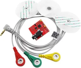
1.1 Electromyography (EMG)
It is technique to collect the information of movement in a muscle. It is based on simple fact that whenever the muscle contracts, a burst of electrical activity is generated which propagates through adjacent tissue and bone and can be recorded from neighboring skin area.
[image:1.595.173.423.335.520.2] [image:1.595.234.377.624.743.2]© 2019, IRJET | Impact Factor value: 7.211 | ISO 9001:2008 Certified Journal
| Page 3404
Fig -3: Muscle Tension & Contraction2. OBJECTIVE OF THE STUDY
The EMG Activity is linearly correlated to the quantity of muscle contraction along with the recorded voltage. By using this voltage signal a servo motor position will controlled.
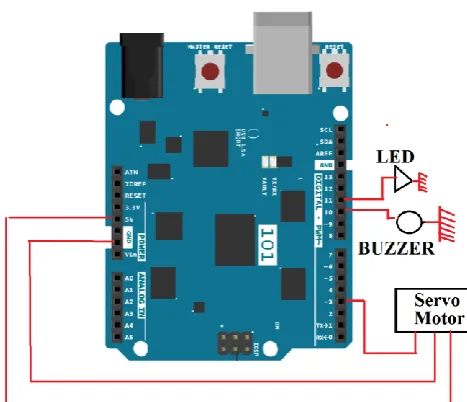
3. CIRCUIT DIAGRAM
In EMG Sensor required Positive & Negative reference voltage. Therefore two power source are required because the sensor has a maximum operating voltage of ±18V,
Fig -4: EMG Sensor & Arduino connection
[image:2.595.187.419.223.459.2] [image:2.595.196.403.592.732.2]© 2019, IRJET | Impact Factor value: 7.211 | ISO 9001:2008 Certified Journal
| Page 3405
Fig -5: Servo Motor, Buzzer, LED – Arduino Connection3. ARDUINO PROGRAM
[image:3.595.63.551.47.307.2]The following program illustrate the position control of servo motor through Arduino atmega controller.
Table -1: Arduino Program
#include <Servo.h>
//Threshold for servo motor control with muscle sensor.
//You can set a threshold according to the maximum and minimum values of the muscle sensor. #define THRESHOLD 250
//Pin number where the sensor is connected. (Analog 0) #define EMG_PIN 0
//Pin number where the servo motor is connected. (Digital PWM 3) #define SERVO_PIN 3
//Define Servo motor Servo SERVO_1;
int ledPin1 = 11; // Attach led to pin 11. int Buzzer = 10; // Attach Buzzer to pin 10.
/*--- void setup ---*/
void setup(){
//BAUDRATE set to 115200, remember it to set monitor serial properly. //Used this Baud Rate and "NL&CR" option to visualize the values correctly. Serial.begin(115200);
//Set servo motor to digital pin 3 SERVO_1.attach(SERVO_PIN);
[image:3.595.178.412.93.294.2]© 2019, IRJET | Impact Factor value: 7.211 | ISO 9001:2008 Certified Journal
| Page 3406
}
//If the sensor is LESS than the THRESHOLD, the servo motor will turn to 10 degrees. else{
SERVO_1.write(0); }
//If the sensor value is greater than the THRESHOLD, the LED & Buzzer turns on.
if (value > THRESHOLD) // creates bool expression for analyzation. if it evaluates to true, {
digitalWrite (ledPin1, HIGH); // turns on Red Led. digitalWrite (Buzzer, HIGH); // turns on Buzzer. }
else // if the if equation evaluates to false the else statement will execute. {
digitalWrite (ledPin1, LOW); // turns off Red Led. digitalWrite (Buzzer, LOW); // turns Off Buzzer. }
delay(500);
//You can use serial monitor to set THRESHOLD properly, comparing the values shown when you open and close your hand. Serial.println(value);
}
4. HARWARE RESULTS
The position control of servo will takes place by Arduino. The results of the actuation are shown below.
4.1 Arm none flex condition
When the arm is in Non-flex condition the servo motor position will be in zero degree & LED, Buzzer are turn off condition for the voltage depolarization in the forearm muscle gives the frequency rise up 162Hz.
© 2019, IRJET | Impact Factor value: 7.211 | ISO 9001:2008 Certified Journal
| Page 3407
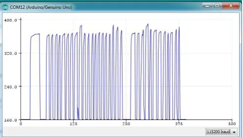
Fig -7: Serial monitor display 162 Hz frequency value during forearm None Flex condition4.2 Arm flex condition
When the arm is in flex condition the servo motor position will turn 180 degree & LED, Buzzer are comes to ON state.
[image:5.595.143.458.297.404.2]Fig -8: Servo Motor “180 Degree position” at forearm flex condition
Fig -9: Serial monitor display greater than 350Hz Frequency value during forearm Flex condition
[image:5.595.173.424.428.570.2] [image:5.595.174.423.594.735.2]© 2019, IRJET | Impact Factor value: 7.211 | ISO 9001:2008 Certified Journal
| Page 3408
REFERENCES[1] Amane Koizumi, Osamu Nagata, Morio Togawa, Toshiyuki Saso, “The Muscle Sensor for an on – site neuroscience lectures
to pave the way for a better understanding of brain – Machine – interface research ” Neuroscience Research 78 (2014) 95-99
[2] Ambily Francis, Neema Mohan, Reshma Roy, “Multi-Tasking EMG Controlled robotic arm”International journal of Advanced
Research in Compuetr & Communication Engineering, Vol.6 Special Issue 4, March 2017.
[3] A.Beneteau, G.Di Caterina, L.Petropoulakis, J.J.Soraghan “Low-Cost Wireless Surface EMG Sensor Using the MSP 430
Microcontroller,” European Embedded Design in Education and Research, 2014
BIOGRAPHIES