Abstract— This study presents a method for recognizing the motion of people using static and mobile laser scanners that are installed in a room and a mobile robot, respectively. We utilized a static sensor equipped with wireless communication in order to overcome the limitations of a sensor that is mounted on a mobile robot, i.e. moving sensor. However, when moving and static sensors are used at the same time, problems inevitably occur during the process of coordinating the data from the different sensors. Moreover, large amounts of information from both sensors need to be processed rapidly for real time computations in realistic environments. In order to cope with these problems, a framework was constructed and studied for tracking people using static and moving sensors. A particle filter was used in localizing robot position in a predetermined map, and Multiple Hypothesis Tracking (MHT) based on Kalman filtering was employed for robust tracking of people. As a result, it was possible to correctly coordinate the information from both sensors. Several experiments were performed in order to test this people tracking method in a realistic indoor environment.
Index Terms— People tracking, Laser scanner, Mobile robot, Ambient sensing
I. INTRODUCTION
nvestigations have been carried out recently regarding the coexistence of robots and humans in the daily environments of humans with a view toward the development of robotic service applications in the near future[1]-[3]. The ability to recognize human motion is considered as one of the the basic capabilities for robots for supporting humans in daily environments. Therefore, many studies have been conducted recently in order to facilitate people tracking using various sensors. In addition, algorithms have been developed for the effective utilization of sensor data via probabilistic methods such as Kalman filtering and Particle filtering [4], [5]. Methods have also been proposed for using multiple mobile robots [6] and for utilizing two-dimensional (2D) range data and image data simultaneously [7]. Further, people tracking capabilities have been implemented using data association methods such as Nearest Neighbor algorithm (NN), Joint Probabilistic Data Association (JPDA) [8], [9], and Multiple Hypothesis Tracking (MHT) [10], [11].
On the other hand, new hardware features and advances in information technology have made it possible to consider
Manuscript received December 23, 2013; revised February 5, 2014. This work was supported by JKA and its promotion funds from Auto RACE*.
Every author is with Mechanical Engineering Course, Graduate school of Science and Engineering, Ehime University, 3 Bunkyo-cho, Matsuyama 790-8577, Japan.
E-mail: Keisuke Okada < [email protected]> Jae Hoon Lee < [email protected] >,
Shingo Okamoto< [email protected] >
new approaches for overcoming the limited internal capabilities of robots. These advances include improvements in wireless communications and sensors such as CCD cameras. There are two main issues that need to be solved in order to realize a sensor-based system that recognizes human movements. First, a method to be developed for recognizing human motions using sensors that are embedded in a robot and in a room as a part of the environmental infrastructure. Second, an algorithm is required for effectively manipulating the large volume of data from the sensors.
Therefore, the purpose of this research is to propose a framework for a people recognition system that includes a static laser scanner in an indoor environment and a mobile robot with a laser scanner. Further, we aim to test the system via experiments that simulate realistic situations. Therefore, an experimental system was developed based on the proposal.
II.SYSTEM CONFIGURATION
A. Overall Architecture and Sensing Condition of the Developed System
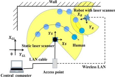
Figure 1 shows the overall architecture of the system developed in this study. It consists of three main parts: a static sensor installed in an indoor environment, a central computer, and a moving sensor. The simplest setup with three representative components is considered in this study. However, the number of sensors can be changed based on the environmental conditions or the application.
[image:1.595.314.537.625.774.2]Laser scanners are employed for both the static and moving sensors. The laser scanner is located at a static position in the indoor environment and is connected to the central computer by a local area network (LAN) communication cable. The moving sensor is attached to the robot and is connected to the central computer by a wireless LAN communication channel. Thus the measurement data from both sensors are transferred to the central computer and the computed results can be utilized by the robot.
Fig. 1. Schematic diagram of system configuration
People Tracking by Collaboration between
a Mobile Robot and Static Laser Scanner
Keisuke Okada, Jae Hoon Lee,
Member, IAENG
, and Shingo Okamoto
B. Sensing Condition of Static and Moving Sensors
The placement of the laser scanners for detecting human motions is displayed in Fig. 2. The height of the static laser scanner is about 90 [cm] from the ground and it is placed at a certain position on the near wall of the room. The moving sensor is set on the upper plate of the robot at a height of about 32 [cm] from the ground. Therefore, the static laser scanner scans the waist sections of humans and the moving laser scanner detects human legs. The static sensor was constructed using LMS100 laser scanner (SICK Co.). The sensor in the mobile robot was constructed using URG-04LX (HOKUYO Co.) laser range finder. The specifications for both laser scanners are listed in Tables 1 and 2. The size of the robot is about 40 [cm] in width, 36 [cm] in depth, and 40 [cm] in height, respectively. The robot has two active wheels that are controlled independently and one caster wheel. The position of the robot is computed via odometry using angle data from both the active wheels.
TABLE Ⅰ
SPECIFICATIONS FOR STATIC LASER SCANNER
Model No. LMS100
Detect range 20m(Max. range with over 75% reflectivity) 270°
Accuracy ±30mm / ±40mm Angular resolution 0.5°
Scan time 20msec / scan
Interface Ethernet 100 Mbit TCP/IP, Size (Weight) 102mm×162mm×106mm ( 1100g ) Manufacturer SICK Co.
TABLE Ⅱ
SPECIFICATION FOR LASER SCANNER INSTALLED IN MOBILE ROBOT
Model No. URG-04LX
Detect range 60 to 4095mm, 240° Accuracy 60 to 1000mm: ±30mm
1000 to 4095mm: ±1% Angular resolution 0.36°
Scan time 100msec / scan Interface USB2.0(Full speed)
Size (Weight) 50mm×70mm×50mm ( 160g) Manufacture HOKUYO Co., Japan
Fig. 2. Side view of the system for detecting humans with laser scanners.
C.Framework Design for the System
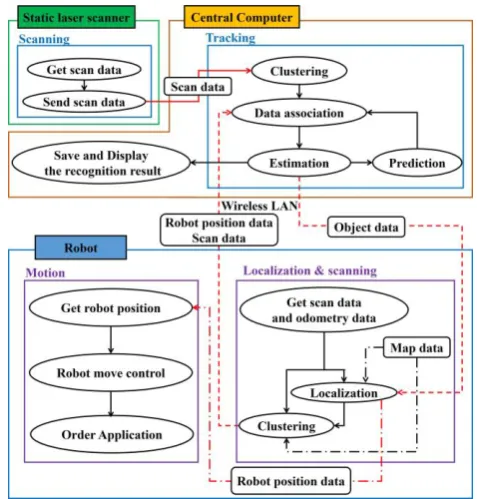
The framework for the people tracking system with static and moving sensors is shown in Fig. 3. The tasks for recognizing the human movements in the room are divided between the central computer and the robot as follows.
The central computer collects the measurement data from both sensors and estimates the positions of people in motion. The first task is to manipulate the measurement data from the static sensor. The computer interfaces with the static sensor
and extracts the measurement set via a ‘clustering’ process. The second task is to estimate the current positions of people using the measurement sets from the static sensor and the moving sensor, where the processes of “prediction,” “association,” and “estimation” are carried out. The third task is to interface with the mobile robot. The computer receives the raw data from the moving sensor, the measurement set that is processed by the robot, and the odometry data in real time. Consequently, it sends the estimation results to the robot. The fourth task is to display and save the sensor data and the resulting information for the users.
[image:2.595.306.545.386.636.2]The mobile robot scans the local environment and sends the measurement data to the central computer. One basic precondition is that the positions of the static sensor and the moving sensor are definitely known, because all of the information must be coordinated based on the positions and directions of both sensors. However, the position of the mobile robot is computed via odometry and errors occur inevitably as a result. In order to solve the problem, the mobile robot is localized based on the map data. Therefore, the robot has functions for localizing itself, clustering the sensor data, and interfacing with the central computer. A Sensor Sharing Manager (SSM) program is installed in the computer on the robot and is used to efficiently manipulate the data from the multiple, internal sensors. The SSM software coordinated the scan data and the odometry data as shown in Fig 4.
Fig. 3. Framework of the system for recognizing human movements with a mobile robot and a static laser scanner.
[image:2.595.329.526.673.778.2]III. RECOGNIZING PEOPLE WITH A STATIC LASER SCANNER
A. Detecting People with a Static Laser Scanner
[image:3.595.303.548.46.453.2]Using the scan data, we can observe the surrounding environment and detect the humans that are included in it. Figure 5 shows a schematic diagram for detecting humans using a laser scanner. The human positions can be detected by comparing the present scan data with the reference data that is saved at the time when no human is present in the area. The differences in the data set signify the people who have entered the environment at a later time. The process for extracting the differences is called ‘clustering,’ and a set of scan points that are grouped together in the same region are referred to in this paper as a ‘cluster’ or a ‘measurement.’ The differences can be divided into multiple clusters by comparing the distances between the adjacent points in the clusters. The clusters with sizes that are similar to the size of an adult’s waist are classified as measurements that represent humans. As a resultant, the measurement,z j, is given in the form of
rj,j
, which can be converted to a position with respect to the global coordinate based on a laser scanner’s position.Fig. 5. People detection with a static laser scanner
B. Estimating Movements of People
In general, the measurements from the sensors include noise due to the natural characteristics of the sensors, the motions of people, and the limitation of the clustering process. For example, the exact center position of a human cannot be measured because the detected part does not have an ideal shape, such as a complete circle, and is also moving in a random manner. Additionally, there are time delays on the communication channel. The Kalman filtering method is employed in conjunction with a model of human movement in order to compute the optimal states of humans in a stable manner [12]. Figure 6 shows a schematic representation of the state estimation process for tracking human movements. In this figure, i denotes the number of humans, j denotes the number of measurement values, k denotes time. For example,
x i(k+1) denotes the predicted state of the i-th human at time k+1, and z j(k+1) denotes the measurement of the j-th human at time k+1. The estimated state of the i-th human at time k is defined by the following equation (1).
k
xi
k yi
k v ix
k v iy
k
xi , , , , , T (1)
It is assumed that the humans were moving via linear uniform motion during the period of sampling time,t. Therefore, the state of the human at time k+1 is represented as follows.
k 1
x
k v ,
k t a2,
k t2/2xi i xi xi (2)
k 1
y
k v ,
k t a2,
k t2/2yi i yi yi (3)
k
v
k a
k tvx,i 1 x,i x,i (4)
k
v
k a
k tvy,i 1 y,i y,i (5) It can be rewritten in the matrix form as
k
Ax
x Qkxi 1 i (7) where, Ais the state transition matrix and is defined as
1 0 0 0 0 1 0 0 0 1 0 0 0 1 t t
A , (8)
and Q
k denotes the system noise that represents the model error and the acceleration of the human object that is being changed randomly. Then, the measurement is given as
k Hx
k W
kzj i (9) where, H is the measurement matrix that is defined as
0 0 1 0 0 0 0 1
H , (10)
k [image:3.595.54.279.320.468.2]W is the measurement noise that represents the error in the measurement of the laser scanner.
Fig. 6. Schematic representation of state estimation for tracking a moving object
C. Data Association for Tracking People
Tracking a moving object requires an association between the measurement of an object’s state at a previous time and the measurement at the current time. The simplest and most widely used method for object tracking is the NN algorithm, which associates the data based on the distance with them. However, NN sometimes fails to make associations correctly when there are many moving objects with complex patterns of motion. The MHT algorithm [10], [11], on the other hand, considers multiple possibilities based on associations that have been proposed. Both of these algorithms were tested as tracking method in the central computer in this study.
[image:3.595.313.524.353.446.2]order to process a higher number of hypotheses and the number of hypotheses increases as time elapses. This issue can be resolved by restricting the number of hypotheses based on the likelihood of each hypothesis.
[image:4.595.303.548.100.612.2]In the example in Fig. 7, only one hypothesis generated by NN that associates the prediction value withZ2
k . Fig. 8, on the other hand, shows the results for MHT for the same situation. Two hypotheses are considered as shown in Fig. 8, and one of them is selected based on the likelihood. [image:4.595.54.271.162.527.2]Fig. 7. Tracking moving objects with NN
Fig. 8. Tracking moving objects with MHT
IV. RECOGNIZING PEOPLE WITH MOBILE ROBOT
A. Localization with Map and Scan Data
It is important to determine the pose of the robot when coordinating its measurement data to that of the static sensor. Odometry data from the robot is helpful for this process, but shows high levels of accumulation errors in the case of long distance navigation. Therefore, a localization algorithm is required in order to guarantee the availability of absolute position information. A particle filter is used in conjunction with map matching for this purpose. The particle filter calculates the likelihood values for multiple particles, analyzes candidates for the solution, and estimates the result based on their values.
Figure 9 shows the concept for localizing the robot with a particle filter that uses map matching. The state of robot pose at time k is defined as
k
R x
k R y
k R
k
R , , φ T. (11)
The state of the b-th particle within the particle sets at time
k is defined as
k
p bx
k pyb
k p b
k
p T
b , , , , φ, . (12)
The motion model for each particle for the state transition is represented by the following equations:
k
p
k V
p
k
tpx,b 1 x,b Rcos φ,b , (13)
k
p
k V
p
k
tpy,b 1 y,b Rsin φ,b , (14)
k
p
k tpφ,b 1 φ,b R . (15) The weight of the b-th particle,wb, is defined as follows:
s m d c bc
b
c , (16)
N
c th bc
b
d d
0
η , (17)
ηb
wb exp1 2, (18)
where, the subscript c denotes the number of scan points, mc denotes the position information for a point in the map,
sbc denotes the position information for the scan data under the hypothesis where the robot is located to the value of the
b-th particle, dth denotes the threshold of error, dbc denotes the index that represents the difference between the scan data and the map data, and ηb denotes the likelihood of the b-th particle, respectively. When dbcis larger thandth,
dthdbc
becomes zero. Finally, the robot state is computed using
k
p
k
w
w w w
R P b P
b b
0 1
0 1 /
1 . (19)
Fig. 9. Estimation of robot position by using particle filter using the map matching method
B. Localization of the Robot by Using the Information from the Central Computer
A new method for estimating the robot position based not only the map, but also on collaboration with the central computer has been considered in this paper. In other words, the robot’s position is recognized by the central computer and is used to improve the performance of localization by the particle filter using map matching.
[image:4.595.316.536.381.621.2]
k
O x
k O y
k
O , T. (20)
The likelihood that the b-th particle represents the robot position is defined as follows
k l
O x
k p bx
k
O y
k pyb
k
lb th , ,
2
2
(21)
k cN
dth dbc
lbb
0
η (22)
where, lth denotes the threshold of the position error. C.Recognizing People with Laser Scanner Embedded on the Robot
A laser scanner installed in a mobile robot detects the human legs. The positions of human legs can be detected by comparing the present scan data with the map data. The data are converted to measurements that denote human positions with respect to the global coordinate of the robot pose. The recognition method is similar to the method used in the case of the static laser scanner.
V.EXPERIMENTAL RESULTS
In this section, the results are described for an experiment that was carried out in the lobby of a building at Ehime University.
A. Recognizing People Using only Static Sensor
The methods for tracking people based on NN and MHT with a static sensor were implemented in the central computer. The performances of the two methods were compared in experiments that involved tracking four people in random waking motions. The scene of the experimental environment is displayed in Fig. 10. Figures 11 and 12 show the experimental results for both algorithms for a test where those were applied to the same experiment at the same time. The motion trajectories of people are depicted by dotted lines. Their walking speed is about 1.2 [m/sec]. The static sensor is located at the position of (0, -3000) [mm]. It can be observed that MHT shows superior performances for long-time tracking and for situations where motions intersect with each other.
B. Robot Localization
The experiments for robot localization were carried out as follows. Two methods were used for localization: the typical method using only map, and the other using both the map and the information from the central computer. Both methods were applied to the same experiment at the same time and the moving speed of the robot was set to about 50 [cm/s].
The experimental results for robot localization using only map information are shown in Fig. 13. For the comparison purposes, the scan data taken from the laser scanner on the mobile robot is depicted based on the robot positions/poses that were computed using odometry and particle filtering with map matching, respectively. The black scan data represent the data that are based on odometry alone. The red scan data represent the data for robot pose based on the particle filter with map matching. It can be observed that the scan data for odometry shows larger position errors than that the scan data for the robot pose based on the particle filter with map matching. Thus, the position data from odometry should be modified by the localization algorithm.
Figure 14 shows the experimental results from the experiment with advanced localization that was conducted using particle filtering with map matching and position
[image:5.595.302.536.143.491.2]information from the central computer. It can be observed that the set of red points, which represent scan data that are coordinated based on the localization results, are closely matched with the map data. It can be observed that the black points, which represent the result from odometry, show large positioning errors for the same experiment. Therefore the proposed method gives the best performances out of all the methods that were tested.
[image:5.595.304.537.512.732.2]Fig. 10. Experimental environment
Fig. 11. Experimental result of recognizing people with the NN algorithm
Fig. 13. Experimental result for robot localization using only the map.
Fig. 14. Experimental result for robot localization using the map and position information from the central computer
[image:6.595.51.276.91.283.2]Fig. 15. Environment for experiment for recognizing walking people using moving and static sensors
Fig. 16. Experimental result for recognizing walking people using static and moving sensors
C.Tracking People by Collaboration between Static Sensor and a Mobile Robot
An experiment for recognizing walking people via collaboration between static and moving sensors were carried out. Figure 15 shows the environment for the experiment. There are two people who are walking in the room. One laser scanner is installed on the mobile robot and a static sensor is installed near the wall. The robot moved at a speed of about 50 [cm/s]. The experimental results, which were computed
by the central computer using data from the static and moving sensors is displayed in Fig. 16. In the results, the robot is located near (1500, 0), and two people are walking near (-500, -500) and (-500, 500), respectively. One person is detected by both sensors. The motions of his legs were tracked and are depicted with green points (by the moving sensor) and with purple points (by the static sensor). The other person was only detected by the moving sensor. The motions of his legs were also tracked and are depicted with green points (by the moving sensor). Therefore, it has been confirmed that the proposed system can recognize walking people.
VI. CONCLUSION
A system for recognizing pedestrians installed with a collaborative algorithm utilizing both static and moving sensors was developed in this paper. A localization method based on a particle filter that used a predetermined map and measurements from the central computer was proposed in order to cope with position errors regarding the mobile robot. For the real implementation, the framework of the entire system was designed based on the tasks and roles of the individual components. The effectiveness of the system was demonstrated in an experiment in a realistic environment. Future studies will focus on extending this proposal to a larger system with multiple sensors and on stabilizing the system in realistic conditions.
REFERENCES
[1] Dylan F. Glas, Kanda Takayuki, Ishiguro Hiroshi and Hagita Norihiro, “Simultaneous People Tracking and Localization for Social Robots Using External Laser Range Finders,” The 2009 IEEE/RSJ International Conference on Intelligent Robots and Systems, pp.846-853, 2009
[2] Sakai Tatsuo, Nakajima Hisato, Yamane Tsuyoshi, Nishimura Daisuke, Uematsu Hiroyuki and Kitano Yukihiko, “Development of Hospital Delivery Robot System,” TRANSLOG2004, pp.69-72, 2004 [3] Takayuki Kanda, Hirano Takayuki and Daniel Eaton, “Interactive
Robots as Social Partners and Peer Tutors for Children: A Field Trial,” Human Computer Interaction, vol.19, pp.61-84, 2004
[4] Dirk Schulz, Wolfram Burgard, Dieter Fox and Armin B. Cremers, “Tracking Multiple Moving Objects with a Mobile Robot,” Proceedings of the 2001 IEEE Computer Society Conference, vol.1, pp.371-377, 2001
[5] Yougjin Hong, Myungjin Jung, Hyun Myung, Hyoungki Lee, Yongbeom Lee and Sangryong Kim, “Detecting and Tracking People by Mobile Robot Using Structured Light Range Sensor,” International Conference on Intelligent Robots and Systems, pp.2864-2869, 2005. [6] Nicolas A. Tsokas, and Kostas. Kyriakopoulos, “Multi-Robot Multiple
Hypothesis Tracking for Pedestrian Tracking,” Auton Robot ,pp.33-76, 2011
[7] Sokabe Koji, Kurazume Ryo, Iwashita Yumi, and Hasegawa Tsutomu, “Target Tracking by Laser Sensor and Camera using JPDAF and Color Histogram,” The 11th SICE System Integration Division Annual Conference , pp.603-606, 2010
[8] Hatao Naotaka, Tokita Youishi, and Kagami Satoshi, “Tracking and Identification of Moving Objects Using Cluster Based SJPDAFs,” Proceedings of the 2012 JSME Conference on Robotics and Mechatronics , 2P1-O06, 2012
[9] T.E.Fortmann, Y.Bar-Shalon and M.Scheffe, “Multi Target Tracking using Joint Probabilistic Data Association,” Proc.19th IEEE Conference Decision and Control, pp.807-812, 1980
[10] D.B.Reid., “An Algorithm for Multiple Targets,” IEEE Transactions on Automatic Control, vol AC-24, No.6, pp.101-104, 1979
[11] Samuel S. Blackman, “Multiple Hypothesis Tracking for Multiple Target Tracking,” IEEE Aerospace and Electronic Systems Magazine Vol.1, pp.5-18, 2004
[image:6.595.81.258.318.415.2] [image:6.595.57.287.437.639.2]