Abstract—Bone as a natural composite material has a
complex hierarchical and heterogeneous structure. It is quite difficult to analyze the mechanical behavior of cortical bone due to various constraints associated with the specimen preparation. These constraints may be overcome using small size specimens of cortical bone. Small punch testing, used in the present study, is a very useful technique to analyze the deformational behavior of materials that are difficult to obtain in a sufficient size for conventional mechanical testing. The finite element modeling (FEM) of small punch testing was carried out using ABAQUS code. The material properties of cortical bone for FE simulation were considered to be both isotropic and transversely isotropic in nature. This way total six independent FE models were developed and their results were compared with the corresponding experimental one. As per the study, the FE results of 1.0 mm thick specimen were observed to be closer to the corresponding experimental results. However, for 1.5 mm thick specimen the FE model results were found to be significantly deviated from the experimental results. The heterogeneous and hierarchical structure of cortical bone was considered to be the main cause of this deviation. This study shows that isotropic tensile properties of cortical bone are sufficient to predict the deformational behavior of cortical under small punch testing.
Index Terms— Small punch testing, Cortical bone, Finite
element simulation, Transversely isotropic material
I. INTRODUCTION
ONE is a well known heterogeneous and anisotropic material. The anisotropy in mechanical properties of bone has been regarded as being caused by a characteristic composite structure of constituents in bone. The main constituents of bone are rigid hydroxiapatite like minerals and pliant collagen fibril [1-5]. The mechanical properties of cortical bone are difficult to obtain due to various constrains such as complexity in bone material, shape and size of bone, availability of the specimen from bone diaphysis, testing procedures etc [6-10]. These constraints may be overcome by employing small size
Manuscript received July 23, 2013.
N. K. Sharma was with the Indian Institute of Technology Delhi, Hauz Khas, New Delhi 110016, India. He is now with the Glocal University, Mirzapur Pole, Saharanpur, Uttar Pradesh 247122, India (phone: +91-9310664161; e-mail: enksharma@ yahoo.com).
Swati Sharma is with the Indian Institute of Technology Delhi, Hauz Khas, New Delhi 110016, India (phone: +91-8744868155; e-mail: [email protected]).
D. K. Sehgal is with the Indian Institute of Technology Delhi, Hauz Khas, New Delhi 110016, India (e-mail: [email protected]).
R. K. Pandey is with the Indian Institute of Technology Delhi, Hauz Khas, New Delhi 110016, India (e-mail: [email protected]).
specimens for mechanical testing. The advantage of small size specimens includes the possibility of sampling very small volume of material within a heterogeneous structure such as cortical bone. This may also be used for studying biological materials that are not available in volumes sufficient enough for conventional mechanical testing. The small specimen test techniques include a wide array of types and techniques as described by Lucas [11] and Cheon et al. [12]: tensile test, micro hardness, small punch (ball, shear, and hemispherical head), bend, fracture, impact, and fatigue.
In the present investigation the mechanical behavior of cortical bone has been studies using small specimen testing and finite element (FE) simulation. The load-displacement behavior of cortical bone specimens was analyzed with the help of small punch testing technique. The small punch test is a version of the bulge test, the name given by Baik et al. [13]. Manahan et al. [14] and Huang et al. [15] were among the earliest to study the small punch test technique for the determination of mechanical properties of irradiated materials from small circular disks. These techniques largely involve loading a supported disc or coupon with an indenter or punch, deforming it to failure, and analyzing the resulting load-displacement data.
The finite element method (FEM) is a very versatile numerical technique for solving engineering problems of plasticity, impact mechanics, structural analysis and computational mechanics. The FE simulation of small punch test is a large deformation problem and was carried out using the commercially available ABAQUS code. The main advantage of applying FEM to large deformation problems is its versatility, i.e. its ability to simulate the progress of the deformation process and to obtain a complete solution to the problem including the deformation shape, nodal displacement, nodal velocity and distribution of stresses and strains. In the present study six different FE models of small punch test were developed and compared with the experimental results. For different FE models bone material was considered to be isotropic as well as transversely isotropic in nature.
II. MATERIALS AND METHOD
Whole femoral cortical bones of bovine have been procured for the present investigation. After removal of the soft tissue the bones were soaked in normal saline and wrapped in normal saline soaked cloth. These bones were further kept in plastic bag and stored at -20°C before processing. The tensile properties of cortical bone in longitudinal direction (load being applied along the long axis of bone) and transverse directions (load being applied perpendicular to the long axis of bone) were evaluated using
Studies on Deformational Behavior of Cortical
Bone using Small Punch Testing and Finite
Element Simulation
N. K. Sharma, Swati Sharma, D. K. Sehgal, and R. K. Pandey
strip type dumbbell shape specimens. The longitudinal tensile specimens were prepared with gauge length 25 mm, gauge width 4 mm and total length 80 mm, whereas, the transverse tensile specimens were prepared with gauge length 8 mm, gauge width 4 mm and total length 22 mm. Poisson‟s ratio in each direction was tested with the help of biaxial extensometer of gauge length 25 mm. The longitudinal and transverse compressive properties of cortical bone were determined using cubic specimens of each edge equal to 5 mm. For small punch testing on cortical bone the small specimens were prepared with rectangular cross-section having 2 mm width and two different thicknesses of 1 and 1.5 mm. The length of these specimens was maintained equal to 10 mm. These longitudinal small specimens of cortical bone were prepared such that their length coincided with the long axis of the femur. The longitudinal small specimens of cortical bone prepared for small specimen testing are shown in Fig. 1.
Fig. 1. Small longitudinal rectangular specimens of cortical bone of different thicknesses (i.e. 1 mm, 1.5 mm)
[image:2.595.316.544.186.477.2]All different specimens for experimental testing were obtained from the middle diaphysis of the femoral bone and were stored at room temperature in a solution of 50% saline and 50% ethanol at all time until testing. Different experimental tests were conducted on MTS 858 Table Top Machine with very slow strain rates (i.e. 1.8 mm/min for tensile and compressive testing and 0.5 mm/min for small specimen testing). The fixture for small punch testing and its installation on MTS 858 table top machine is shown in Fig. 2.
Fig. 2. Setup for small punch testing, (a) fixture for small punch testing and (b) installation of fixture on MTS 858 table top machine
The rectangular shape small specimen geometry is clearly not axisymmetric, so a three dimensional finite element model is required. In this study, a three dimensional finite element model has been proposed for simulating small punch test with rectangular shape small (fixed beam)
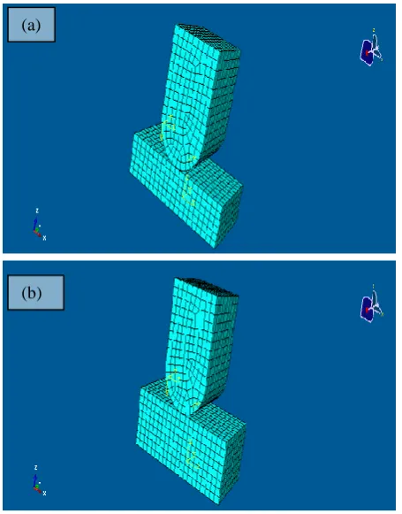
specimen under quasi-static loading by special cylindrical tip headed rigid punch. ABAQUS standard package is used for computation and detailed computational results are obtained. For simulation the dimensions of the rectangular specimen are decided according to the inner square (4 mm x 4 mm) cross-section of the borehole of the specimen holder. The three dimensional FE models of small specimen test in case of 1 mm and 1.5 mm thicknesses of the small cortical bone specimens are shown in Fig. 3. These models were discretized with second order 20-noded brick (hexahedra) elements.
Fig. 3. Three dimensional FE models of small punch test in case of (a) 1 mm and (b) 1.5 mm thicknesses of the small specimens
The size of the cylindrical headed punch is considered as 1.82 mm diameter, 2.0 mm width and 4 mm height. The cylindrical headed tip rigid punch is modelled with rigid body option using rigid element from ABAQUS library. Two opposite side edges of the small specimen are considered as fixed by boundary condition option ENCASTER (motion constrained in all direction). Top surface of rectangular specimen is defined as SLAVE surface for interaction. The cylindrical tip surface of rigid punch is defined as MASTER surface for interaction. A close surface interaction of SLAVE and MASTER surface is defined by contact algorithm. The quasi-static loading simulation is simulated with amplitude option and small incremental steps are used at reference node of cylindrical tip punch.
For FE simulation, cortical bone material was considered to be both isotropic and transversely isotropic in nature. The small specimen in shear punch testing is under pure bending situation, therefore, the upper surface of the specimen is under compression whereas the lower surface is under tension. This necessitates the partitioning of the small specimen as bone material may behave in a different manner
(a) (b)
(a)
[image:2.595.84.220.274.355.2] [image:2.595.48.290.531.693.2]under tensile and compressive loading. Therefore the behaviour of cortical bone specimen under small punch testing was analyzed using six independent FE models. These models were categories according to the specified material properties as; FTTI (having fully tensile mechanical properties considering bone material to be transversely isotropic), TCTI (having different behaviour under tension and compression with transversely isotropic material properties), FCTI (having fully compressive mechanical properties considering bone material to be transversely isotropic), FTI (having fully tensile mechanical properties considering bone material to be isotropic in nature), TCI (having different behaviour under tension and compression with isotropic material properties) and FCI (having fully compressive mechanical properties considering bone material to be isotropic in nature). The anisotropic yielding criterion in case of transversely isotropic material properties was specified using Hill‟s potential functions [16].
III. RESULTS AND DISCUSSION
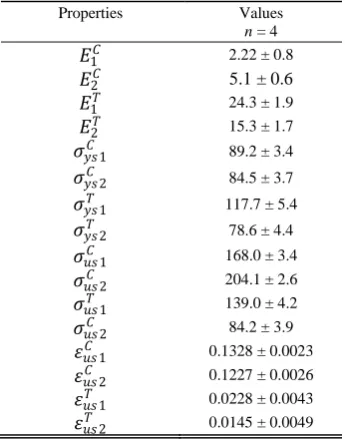
The tensile and compressive properties of cortical bone obtained from different experimental procedures are listed in Table 1. The notations used for different mechanical properties for tensile and compressive loadings and in longitudinal and transverse directions are as given below;
𝐸𝑖𝑠 = Elastic modulus of cortical bone in GPa 𝜎𝑦𝑠𝑖𝑠 = Yield stress of cortical bone in MPa 𝜎𝑢𝑠𝑖𝑠 = Ultimate strength of cortical bone in MPa 𝜀𝑢𝑠𝑖𝑠 = Fracture strain of cortical bone
where i = 1, 2 for respectively longitudinal and transverse directions of loading
and s = C, T for respectively the compressive and tensile loading
[image:3.595.305.536.56.243.2]The different tested specimens of cortical bone in case of compression, tension and small punch testing are shown in Fig. 4.
Fig. 4. Different tested specimens of cortical bone under (a) compression (b) tension and (c) small punch testing
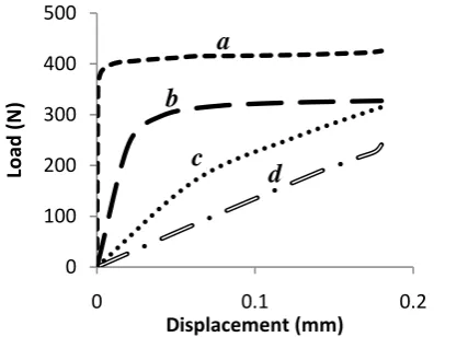
The experimental load-displacement diagrams obtained from small punch test have been compared with different load-displacement diagrams obtained from the FE models in case of both 1 mm and 1.5 mm thicknesses of the small specimen. The comparisons of experimental load-displacement curve with those obtained from FE transversely isotropic models are shown in Fig. 5 and Fig. 6 respectively for 1 mm and 1.5 mm thicknesses of the specimen, whereas, the corresponding comparisons with those obtained from FE isotropic models are shown in Fig. 7 and Fig. 8 respectively for 1 mm and 1.5 mm thicknesses.
Fig. 5. Comparison between experimental and transversely isotropic finite element load-displacement diagrams for 1.0 mm thick small specimen (where a = experimental curve, b = FTTI, c = TCTI and d = FCTI)
Fig. 6. Comparison between experimental and transversely isotropic finite element load-displacement diagrams for 1.5 mm thick small specimen (where a = experimental curve, b = FTTI, c = TCTI and d = FCTI)
0 50 100 150 200
0 0.1 0.2 0.3
Load
(N
)
Displacement (mm)
0 100 200 300 400
0 0.05 0.1 0.15 0.2
Load
(N
)
Displacement (mm)
TABLEI
PROPERTIES OF CORTICAL BONE ALONG DIFFERENT
MATERIAL ORIENTATIONS AND LOADING CONDITIONS
Properties Values
n = 4
𝐸1𝐶 2.22 ± 0.8
𝐸2𝐶 5.1 ± 0.6
𝐸1𝑇 24.3 ± 1.9
𝐸2𝑇 15.3 ± 1.7
𝜎𝑦𝑠1𝐶 89.2 ± 3.4
𝜎𝑦𝑠2𝐶 84.5 ± 3.7
𝜎𝑦𝑠1𝑇 117.7 ± 5.4
𝜎𝑦𝑠2𝑇 78.6 ± 4.4
𝜎𝑢𝑠1𝐶 168.0 ± 3.4
𝜎𝑢𝑠2𝐶 204.1 ± 2.6
𝜎𝑢𝑠1𝑇 139.0 ± 4.2
𝜎𝑢𝑠2𝐶 84.2 ± 3.9
𝜀𝑢𝑠1𝐶 0.1328 ± 0.0023 𝜀𝑢𝑠2𝐶 0.1227 ± 0.0026 𝜀𝑢𝑠1𝑇 0.0228 ± 0.0043 𝜀𝑢𝑠2𝑇 0.0145 ± 0.0049 n = number of specimens tested and the values reported here are the average values.
a
b
c
d
a
b
c
d
(a)(b)
[image:3.595.315.507.424.550.2] [image:3.595.79.252.508.728.2] [image:3.595.318.522.609.741.2]Fig. 7. Comparison between experimental and isotropic finite element load-displacement diagrams for 1.0 mm thick small specimen (where a = experimental curve, b = FTI, c = TCI and d = FCI)
Fig. 8. Comparison between experimental and isotropic finite element load-displacement diagrams for 1.5 mm thick small specimen (where a = experimental curve, b = FTI, c = TCI and d = FCI)
The experimental and FE results of small punch test are reported in Table II for different thicknesses of the small specimen.
As per the unpaired t-test analysis, for 1.0 mm thick longitudinal specimen, the failure load obtained from experimental curve was not found to be significantly
different from finite element results of TCTI, FCTI, FTI, TCI, and FCI, however, it was significantly different (p < 0.05) from FTTI model result. On the other hand, the stiffness values of experimental curves were found to be significantly different (p < 0.00000001) from all finite element results. The experimental load at breakaway point (load point corresponding to 0.2 % offset point) was not observed to be significantly different from finite element results of TCTI, FTI, and FCI while it was observed to be significantly different (p < 0.01 FCTI and p < 0.05 for FTTI and TCI) for FTTI, FCTI and TCI as compared to experimental result.
For 1.5 mm thick specimen, the experimental failure load was found to be significantly different (p < 0.0001 for FTTI, TCTI and FCI, p < 0.001 for FCTI, p < 0.005 for FTI and p < 0.01 for TCI) from all finite element results. The stiffness of experimental curve was found to be significantly different (p < 0.00000001) from all finite element curves. Similarly, the load at breakaway point of experimental curve was also observed to be significantly different (p < 0.0001 for FTTI, FCTI, TCI and p < 0.001 for TCTI and FCI, p < 0.01 for FTI) from all finite element curves.
As per the above discussion, the experimental and finite element results were found to be significantly different in case of 1.5 mm thick small specimen, whereas, for 1.0 mm thick small specimen the corresponding experimental and FE models results were not significantly different. This shows that thickness of the cortical bone specimen plays an important role during deformation of bone. The hierarchical composite like structure of cortical bone may be the main reason of this deformational behaviour. Further, bone is considered to be highly heterogeneous material due to variation in its compositional parameters such as density, porosity, mineralization etc., however, for FE simulation the material was considered to be homogenous. The mismatch between experimental and FE model results of 1.5 mm thick specimen shows that as specimen thickness increases the material becomes more heterogeneous in nature. Therefore, for small specimen testing the FE models of bone specimens having less than 1.5 mm thickness can predict closer results to the experimental one. It is also evident from this study that the load-displacement curve obtained from isotropic fully tensile FE mode (FTI) is closer to the experimental curve. This shows that tensile properties are dominating in case of small punch testing and bone material behaves almost isotropic in nature.
IV. CONCLUSION
The deformational behavior of cortical bone was analyzed using small punch testing. The small punch testing was conducted on small cortical bone specimens of two different thicknesses (1.0 mm and 1.5 mm). The finite element simulation of small punch test was carried out using ABAQUS software to compare the load-displacement behavior of cortical bone. The deformational behavior of cortical bone under small punch testing was modeled using transversely isotropic as well as isotropic material properties of bone. Various cases have been incorporated in FE simulation of cortical bone after partitioned the small rectangular specimen from the middle. Tensile and compressive properties obtained from full size tests have
0 50 100 150 200
0 0.1 0.2 0.3
Load
(N
)
Displacement (mm)
0 100 200 300 400 500
0 0.1 0.2
Load
(N
)
Displacement (mm)
a
b
c
d
a
b
c
d
TABLEII
EXPERIMENTAL AND FINITE ELEMENT RESULTS OF SMALL PUNCH TEST
Method
Specimen thickness (mm)
Failure load
(N)
Stiffness (kN/mm)
Load at break away
(N) Exp
results
1.0 172.26 398.18 151.71
1.5 425.62 525.09 166.67
FTTI 1.0 136.04 5.04 105.71
1.5 220.49 7.99 166.67
TCTI 1.0 148.12 1.48 123.57
1.5 237.64 2.38 211.39
FCTI 1.0 166.29 1.21 94.89
1.5 253.65 3.45 119.24
FTI 1.0 1.5 194.19 327.41 11.99 6.92 133.69 249.79
TCI 1.0 192.03 1.46 113.07
1.5 314.83 2.74 177.02
FCI 1.0 160.05 0.68 146.88
[image:4.595.66.280.285.439.2]been fed to the software to perform the FE simulation. The FE results of 1.0 mm thick specimen were found to be in better agreement with the corresponding experimental results. The deviation in FE and experimental load-displacement curve for 1.5 mm thick specimen was considered to be due to hierarchical and heterogeneous nature of cortical bone. From this investigation it was observed that isotropic tensile properties are sufficient to better simulate the small punch testing of cortical bone.
REFERENCES
[1] N. Sasaki, N. Matsushima, T. Ikawa, H. Yamamura, and A. Fukuda, “Orientation of bone mineral and its role in the anisotropic mechanical properties of bone-transversely anisotropy,” Journal of Biomechanics, vol. 22, pp. 157-164, 1989.
[2] S. Weiner, and H. D. Wagner, “The material bone: structure-mechanical function relations,” Ann Rev Mater Sci, vol. 28, pp. 271-298, 1998.
[3] R. A. Robinson, and S. R. Elliot, “The water content of bone: I. The mass of water inorganic crystals, organic matrix, and „CO2 space‟ components in a unit volume of dog bone,” Journal of Bone Joint Surgery, vol. 39 A, pp. 167-188, 1957.
[4] R. B. Martin, Porosity and specific surface of bone. CRC Critical Reviews, 1984.
[5] E. Lucchinetti, “Composite models of bone properties,” in Bone Mechanics Handbook, 2nd ed. ch. 3, Boca Raton, Ed. FL: CRC Press, 2001, pp. 12.1–12.19.
[6] J. McElhaney, J. Fogle, E. Byars, and G. Weaver, “Effect of embalming on the mechanical properties of beef bone,” J Appl
Physiol, vol. 19, pp. 1234–1236, 1964.
[7] R. W. McCalden, J. A. McGeough, M. B. Barker, C. M. Courtbrown, “Age related-changes in the tensile properties of cortical bone: The relative importance of changes in porosity, mineralization and microstructure,” J Bone Joint Surg Am, vol. 75A, pp. 1193–1205, 1993.
[8] F. G. Evans and M. Lebow, “Regional differences in some of the
physicalproperties of the human femur,” J Appl Physiol, vol. 3, pp. 563–572, 1951.
[9] D. T. Reilly, A. H. Burstein, and V. H. Frankel, “The elastic modulus for bone,”Journal of Biomechanics, vol. 7, pp. 271–275, 1975.
[10] N. K. Sharma, D. K. Sehgal, and R. K. Pandey, “Studies on locational variation of shear properties in cortical bone with Iosipescu shear test,” Applied Mechanics and Materials, vol. 148-149, pp. 276-281, 2012.
[11] G. E. Lucas, “Review of small specimen test technique for irradiation testing,” Metallurgical Transaction A, vol. 21A, pp. 1105-1119, 1990. [12] J. S. Cheon and I. S. Kim, “Initial deformation during small punch
testing,” Journal of Testing and Evaluation, vol. 24, pp. 255-262, 1996.
[13] J. M. Baik, J. Kameda, and O. Buck, “Small punch test evaluation of inter-granular embrittlement of an alloy steel,” Scripta Metallurgica, vol. 17, pp. 1443-1447, 1983.
[14] M. P. Manahan, A. S. Argon, and O. K. Harling, “The development of miniaturized disk besnd test for the determination of post irradiation mechanical properties,” Journal of Nuctear Materials, vols. 103-104, pp. 1545-1550, 1981.
[15] F. M. Huang, M. L. Hanilton, and G. L. Wire, “Bend testing for miniature disk,” Nuclear Technology, vol. 57, pp. 234, 1982. [16] N. K. Sharma, D. K. Sehgal, R. K. Pandey and R. Pal, “Finite element