Temperature Dependent Performance of
Multi-walled Carbon Nanotubes as VLSI Interconnects
for Variable Interconnects Length
Karmjit Singh Sandha
Member, IAENG
and Balwinder Raj
Abstract: This paper presents the influence of temperature on the performance of Multi-walled carbon nanotubes (MWCNT) for very large scale integration (VLSI) interconnects at variable interconnect length for deep-sub micron technology nodes. The impact of temperature variations (200K-450K) on the impedance parameters of MWCNTs as VLSI interconnects for variable interconnect length is analyzed. It is revealed from the results that for higher side of the temperature range, the resistance of the MWCNT is severely affected by the impact of temperature and need to be addressed for accurate performance of Integrated Circuits (IC). Further, a comparative analysis of temperature dependent performance of MWCNT and copper interconnects for global level interconnect length at 32nm, 22nm and 16nm technology nodes with temperature ranging from 200K to 450K, is also presented. It is also observed from the results that MWCNT interconnects offered lesser resistance compared to copper interconnects for all the interconnect lengths under consideration at variable temperature for deep-sub micron technology nodes.
Keywords: Impedance Parameters, MWCNT, Mean Free Path, Scattering Mechanism, Technology Nodes
I. INTRODUCTION
With advancements in the technology nodes, the cross-sectional dimensions of the devices and interconnects of an integrated circuits (ICs) are scaled down to nanometers. For deep-sub micron technology nodes, it is quite difficult for the conventional copper interconnects to satisfy the design requirements of high performance ICs. In the literature, Carbon Nanotubes (CNTs) have been considered as alternative material to the conventional copper, as global level interconnect material for high performance IC design[1], [2].
The CNTs are classified into two types: Single-Walled Carbon Nanotubes (SWCNTs) and Multi-Walled Carbon Nanotubes (MWCNTs). An SWCNT is a single rolled sheet of graphene, with diameter from 0.4nm to few nanometers. When many SWCNTs having variable diameters are nested concentrically inside one another, known as MWCNT.[5]-[7].
Manuscript received June 18, 2016; Revised August 2, 2016.
Karmjit Singh Sandha is with Department of Electronics and Communication Engineering, Thapar University, Patiala, India. (Mobile no: +91-9646020543, email: [email protected]).
Balwinder Raj is with Department of Electronics and Communication Engineering with National Institute of Technology, Jallandhar, India. ([email protected])
The temperature variations for high performance IC design may influence the desired performance of an IC. Hence the correctness of the sensitive systems may have large variations under variable thermal atmosphere conditions for their different applications.
These thermal variations may have substantial impact on scattering phenomenon and mean free path (MFP) of MWCNT, which influences the impedance parameters of MWCNT interconnects[8]-[17]. This paper includes the influence of temperature on scattering phenomenon for MWCNT and proposed a impedance model for MWCNT interconnect which includes the impact of temperature, for different interconnects lengths i.e. from 200µm-2000µm, at global level interconnects for nano-scaled technology nodes. For comparative analysis, temperature dependent analysis is performed for copper interconnects and results are compared with MWCNT interconnects for global interconnects length.
The work is presented in five sections. Section II presents a temperature dependent R-L-C equivalent circuit model for MWCNT at variable interconnect length. The results obtained from proposed models are analyzed in Section III. Finally, conclusion is drawn in Section IV.
II. TEMPERATURE DEPENDENT EQUIVALENT
CIRCUIT MODEL
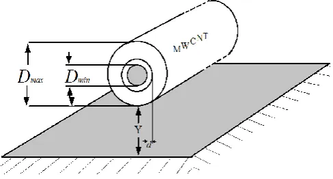
The schematic structure of MWCNT consists of several shells with variable diameter and concentrically nested inside one to another, as shown in Fig. 1. Douterand Dinner
[image:1.595.308.552.597.728.2]are the diameters of outermost and innermost shells of the bundle and Y is the distance from the center of the bundle to the ground plane. Two adjoining shells are separated with the van der Waals distance and it is δ≈0.34nm [6].
.
,
3
chan i i
shell
N
a D
b
for D
nm
A. Number of shells and conducting channels: The number of conducting shells in a bundle can be counted on the basis of outermost diameter of the bundle and its diameter ratio i.e. the ratio of diameters of innermost to outermost shell (Dinner/Douter,). The number of shells are
counted from outermost to innermost as I,II,III, i,…, p. [6]-[17].
Thus, the number of shells p, of any ithshell in the MWCNT can be calculated as [6]-[12]
(1)
The conducting channels for a shell having diameter less than 3nm are approximately considered equal to 2 and shells having diameters more than 3nm are diameter dependent. Therefore, conducting channels of any ithshell of MWCNT can be given as
(2)
Where Di is the diameter of ithshell, a=6.12x10⁻⁴ 1/(nmK)
and b=1.275.
[image:2.595.50.288.370.494.2]B. Temperature dependent R-L-C circuit model of a Shell: Based on temperature dependent interconnect parasitic, the R-L-C equivalent circuit model of any ith shell of MWCNT is shown in Fig. 2.
Fig. 2. Temperature dependent R-L-C model of an individual ith shell of MWCNT [6]
1. Resistance (Rshell) of ith shell of MWCNT
The resistance of individual ith shell of MWCNT having of three types of resistances [6]. These are temperature dependent scattering resistance (Rs), quantum resistance
(Rq), and imperfect contact resistance (Rc). The contact
resistance is depending upon growing process and ranging from few ohms to few tens of k-ohms. [6]-[9]. The contact resistance is independent from temperature and considered to be equal to 2kΩ for each shell of the bundle for this paper. Therefore, the resistance of each shell [6]-[9] is given by 2 2 . 2 . ( ) 2 2
shell c q s
i i
R R R R L
h h L
k
eff T
e N e N
(3)
Where h/2e2= 12.9kΩ, λeff(T), L and Ni are the MFP
(temperature dependent), interconnect length and conducting channels of an individual shell respectively. Eq. (3) shows that λeff(T) and interconnect length (L) are the
important parameters used to calculate the scattering
resistance (Rs) of each shell, where MFP of each shell
depends upon its scattering phenomenon. [7], [9], [10]. The scattering phenomenon is classified into two types: electron-phonon and electron-electron scattering.
The electron-electron scattering has negligible role to play where the electron-phonon scattering is the key factor for MFP of the shells of MWCNT [7], [9]. The electron-phonon scattering phenomenon for MWCNT is further divided into two types: acoustic scattering and optical zone-boundary scattering. Therefore, the scattering dependent effective MFP (λeff) can be given as
. AC oz eff AC oz
(4)
Where λAC is acoustic MFP which is because of acoustic
scattering and λoz is optical zone-boundary MFP. For modest
temperature, the main source of resistance for MWCNT is the acoustic phonon scattering MFP (λAC) [7] and it depends
upon the temperature and diameter of the shell and given as
900 0 iAC T D T T (5)
Where T0=300K, T is temperature in Kelvin and Di is
diameter for related shell of the bundle [6]-[11]. It is shown in Eq. (5) that the temperature is inversely proportional to acoustic MFP (λAC). Therefore, the rise in temperature is
responsible to shrink the acoustic MFP (λAC) hence
decreases the total MFP. For moderate to high temperature range, the optical zone boundary MFP (λoz) also plays the
considerable role. [6]-[9]. Therefore, λoz can be written as
, ,
, ,
.
oz fld oz abs
oz
oz fld oz abs
(6)Where, 𝜆oz,fld measure as the scattering effect due to the
electric-field acceleration and can be represented as
,300 , 300 1 ( ) 1 oz i oz Boz fld
o oz
D N
h k T
L
eV D N T
(7)
The optical and zone-boundary phonon occupied states are defined as the density of states and given by Noz =1/ [exp
(hω/kBT)-1]. λoz,absdue to the scattering effect of absorbing
of an optical/zone-boundary phonon and can be represented as [6]-[9]
,300 , 300 1oz i oz oz abs
o oz
D N
D N T
(8)
Therefore, it is revealed from the Eqs. (3-8) that the effective MFP of individual shells of MWCNT depends upon the temperature dependent acoustic, optical and zone boundary scattering phenomenon. Further, this effective MFP influences the resistance of the individual shells.
2. Inductance of ith shell
The inductance is the property of an electrical conductor related to the movement of electrons carrying current (I) through it. Magnetic and kinetic inductances per unit length are the two types of inductance in MWCNT [6], [7] and given as 1 2 . 2 m i Y L cosh D (9)
/ 2 8 /
2 2
k channel f h
L nH m
v e
(10)
// / i
Lk shell Lk channel N
Where Y,h and vf are the space from axis of MWCNT to
ground, Planck constant and Fermi velocity respectively.
3. Capacitance of ith shell
Quantum capacitance (Cq ) and electrostatic capacitance (Ce)
are the types of capacitance of the MWCNT and given as [6]-[9].
2
2 2
193 /
/
e
C aF m
q channel hv f
(12)
.
/ / i
C C N
q shell q channel
(13)
(14)
The potentials of difference of MWCNT shells cannot be considered to be at same level, which introduces inter-shell coupling capacitance. The inter-shell capacitance (Cs) can
be obtained by using the same equation which can be used for coaxial capacitance [6], [9] and given by
(15)
Where, Dout and Din are the diameters of outermost and
innermost of neighboring shells, respectively.
C. R-L-C Equivalent Model for MWCNT bundle
[image:3.595.325.525.174.734.2]On the basis of temperature dependent impedance parameters presented in the previous sub-sections, an equivalent R-L-C circuit model for MWCNT interconnects is shown in Fig. 3. In this circuit model, all the shells of MWCNT bundle an interconnect bundle are considered to be parallel shells.
Fig. 3. R-L-C equivalent circuit for MWCNT. [6]
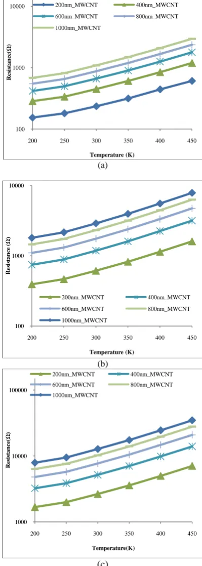
III. RESULTS AND DISCUSSION
The temperature dependent resistance for MWCNT interconnects at deep-sub micron technology nodes i.e. 32nm, 22nm and 16nm, are calculated for different interconnects lengths varying from 200µm-2000µm for variable temperature ranging from 200K-450K. The temperature dependent effective MFP of every shell of a MWCNT for different interconnects length and technology nodes is calculated using Eqs. (4-8). Based on these MFPs for different length and technology nodes, the temperature dependent resistance for all individual shells, are calculated using Eqs. (3). The number of shells for a MWCNT and number of conducting channel in an shell, are calculated by using Eqs.(1-2) respectively. Inductance and capacitance for individual shell are calculated using Eqs. (9-15). Further, the equivalent resistance of MWCNT is obtained by considering all the individual shells in parallel to each other as per the proposed model and shown in the Fig. 3.
It is revealed from the results that with rise in temperature (200K-450K), the resistance for MWCNT increases for 32nm, 22nm and 16nm technology nodes. It is also revealed from the results that with increase in temperature, the resistance is increasing for all the interconnect lengths, varying from 200μm to 1000μm for all the technology nodes under consideration. Therefore, it is mandatory to include the influence of temperature on variable interconnect lengths for deep sub-micron technology nodes to evaluate the accurate performance of a MWCNT interconnects.
(a)
(b)
(c)
Fig. 4 (a), (b) and (c). Temperature dependent resistance of MWCNT interconnects for 32nm, 22nm and 16nm technology nodes respectively for interconnects length 200μm to 1000μm. The resistances are shown on logarithm scale.
100 1000 10000
200 250 300 350 400 450
Re
sis
tan
ce
(Ω
)
Temperature (K)
200nm_MWCNT 400nm_MWCNT
600nm_MWCNT 800nm_MWCNT
1000nm_MWCNT
100 1000 10000
200 250 300 350 400 450
Re
sis
tan
ce
(
Ω)
Temperature (K)
200nm_MWCNT 400nm_MWCNT
600nm_MWCNT 800nm_MWCNT
1000nm_MWCNT
1000 10000 100000
200 250 300 350 400 450
Re
sis
tan
ce
(Ω)
Temperature(K)
200nm_MWCNT 400nm_MWCNT
600nm_MWCNT 800nm_MWCNT
1000nm_MWCNT
2
2 1
Ce
Y cosh
D outer
2 / (
/ (2 2 )C
s ln D D ln D D out in out out
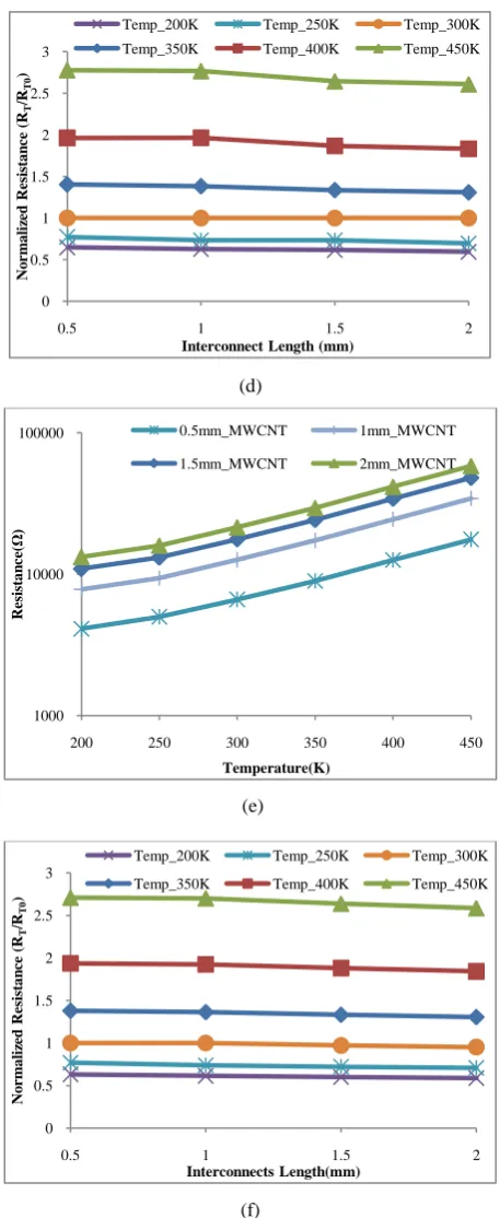
[image:3.595.67.270.439.549.2]Further, the impact of variable temperature on MWCNT interconnects is extended up-to 2mm to understand the impact of temperature on long interconnects. Fig. 5 shows the temperature dependent resistance of MWCNT interconnects at 32nm, 22nm and 16nm technology nodes for interconnects length from 0.5mm to 2mm.
(a)
(b)
(c)
(d)
(e)
(f)
Fig. 5. Temperature dependent resistance of MWCNT interconnects at 32nm, 22nm and 16nm technology nodes for long interconnects lengths from 0.5mm to 2mm. Fig. 5 (a) and (b) Temperature dependent resistance for variable interconnects length on logarithm scale and the normalized resistance (RT/RT0) at 32nm Technology node respectively. Fig. 5 (c) and (d) shows the similar effect for 22nm and Fig. 5(e) and (f) for 16nm respectively.
Fig. 5 (a) and (b) show the temperature dependent resistance for variable interconnects length (0.5mm to 2mm) on logarithm scale and the normalized resistance (RT/RT0)
respectively at 32nm technology node.
It is revealed from the Fig. 5(a) that there is increase in resistance with rise in temperature from 200K to 450K for long interconnects lengths from 0.5mm to 2mm. Fig. 5(b) show the normalized resistance which is the ratio of 100
1000 10000
200 250 300 350 400 450
Re
sis
tan
ce
(
Ω)
Temperature(K)
0.5mm_MWCNT 1mm_MWCNT
1.5mm_MWCNT 2mm_MWCNT
0 0.5 1 1.5 2 2.5 3
0.5 1 1.5 2
No
rm
ali
ze
d
Re
sis
tan
ce
(R
T
/R
T0
)
Interconnect Length(mm)
Temp_200K Temp_250K Temp_300K Temp_350K Temp_400K Temp_450K
100 1000 10000 100000
200 250 300 350 400 450
Re
sis
tan
ce
(
Ω
)
Temperature(K)
0.5mm_MWCNT 1mm_MWCNT
1.5mm_MWCNT 2mm_MWCNT
0 0.5 1 1.5 2 2.5 3
0.5 1 1.5 2
No
rm
ali
ze
d
Re
sis
tan
ce
(
RT
/R
T0
)
Interconnect Length (mm)
Temp_200K Temp_250K Temp_300K Temp_350K Temp_400K Temp_450K
1000 10000 100000
200 250 300 350 400 450
Re
sis
tan
ce
(Ω)
Temperature(K)
0.5mm_MWCNT 1mm_MWCNT
1.5mm_MWCNT 2mm_MWCNT
0 0.5 1 1.5 2 2.5 3
0.5 1 1.5 2
No
rm
ali
ze
d
Re
sis
tan
ce
(
RT
/R
T0
)
Interconnects Length(mm)
Temp_200K Temp_250K Temp_300K
[image:4.595.312.541.45.603.2] [image:4.595.58.282.132.689.2]resistance at any temperature T to the resistance at room temperature (T0=300K). It is observed from results that the
normalize resistance is decreasing as interconnects length increasing, which specify that for longer interconnects, the performance of MWCNT interconnects in terms of resistance is better than smaller interconnects. It is also revealed from the results that the normalized resistance is decreasing more rapidly at moderate to high temperature range (from 300K to 450K) compared lower to moderate temperature range (less than 300K). Therefore, it is concluded that for higher temperature, the resistance is affected by the impact of temperature, more severely and need to be addressed for accurate analysis of MWCNT interconnects. A similar effect is also observed from Fig. 5(c) and (d) for 22nm technology node and Fig. 5(e) and (f) for 16nm technology node respectively. All interconnect parameters used for calculations are obtained from ITRS 2013 [18].
[image:5.595.52.286.367.565.2]Eqs. (9-14) are used to calculate the Inductance and capacitance for MWCNT. These equations show that the inductances and capacitances of MWCNT interconnects are independence from their effective MFP and therefore the impact of temperature variations on inductance and capacitance is negligible small compared to resistance and hence it is ignored in this research work.
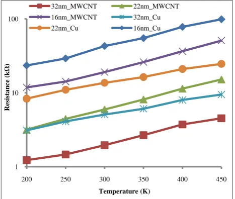
Fig. 6. Comparative analysis of temperature dependent resistance for copper and MWCNT interconnects at global interconnects length (1mm) for 32nm, 22nm and 16nm technology nodes.
For comparative analysis of MWCNT with copper interconnects, temperature dependent equivalent resistance for copper interconnects is calculated by using the temperature dependent equivalent model proposed in [3] and [6]. The comparative analysis in terms of temperature dependent resistance for MWCNT and copper interconnects at 32nm, 22nm and 16nm technology nodes for global interconnects with variable temperature ranging from 200K-450K is shown in Fig. 6.
It is revealed from the results that the resistance for MWCNT and copper interconnects increases as the temperature increases, ranging from 200K-450K. It is also observed from the results that the calculated resistance of
copper interconnects is many time higher than the resistance offered by MWCNT for global interconnects for all the technology nodes under consideration.
IV. CONCLUSION
The paper presented the effect of thermal variation on the resistance of MWCNT and copper interconnects for 32nm, 22nm and 16nm technology nodes. A thermally aware equivalent model is presented for MWCNT interconnects to evaluate and analyze the impact of temperature on resistance, for variable interconnects length(0.5mm-2.0mm). It is revealed from the results that with increased temperature, resistance of each shell of the bundle for all the interconnects lengths increases at all technology nodes under consideration (32nm, 22nm and 16nm). It is also shown that for moderate to high temperature range (300K-450K), the resistance is more severely affected by the impact of temperature and it is need to be addressed for accurate analysis of MWCNT interconnects. Further, it is concluded form the comparative analysis that the resistance offered by copper interconnects is many times higher as compare to MWCNT interconnects. Therefore, it is concluded from the results that for variable thermal environment conditions at different interconnects length, MWCNT is a better conducting material as compare to copper interconnects for VLSI interconnects.
REFERENCES
[1]. Naeemi et al. ―Performance comparison between carbon nanotube and copper interconnects for giga scale integration (GSI),‖ Electron Device letters, vol. 26, No. 2, pp. 84-86, 2005.
[2]. H. Li, C. Xu, N. Srivastava and K. Banerjee, ―Carbon Nanomaterials for Next-Generation Interconnects and Passives: Physics, Status and Prospects,‖ IEEE Trans. Electron Devices, vol. 56, no. 9, pp. 1799-1821, Sep. 2009. [3]. K. Singh, B. Raj, ―Influence of Temperature on MWCNT
bundle, SWCNT bundle and Copper interconnects for Nanoscaled Technology nodes,‖ Journal of Materials Science: Materials in Electronics. vol. 26, no.8, pp 6134-6142, August 2015.
[4]. N. Srivastava, K. Benerjee, ―Performance analysis of carbon nanotubes for VLSI applications,‖ In. IEEE/ACM Intl. Conf. on ICCAD, pp. 383-390, 2005.
[5]. N. Srivastava, H. Li, F. Kreupl, and K. Banerjee, ―On the applicability of single-walled carbon nanotubes as VLSI interconnects,‖ IEEE Trans. Nanotechnology., vol. 8, no. 4, pp. 542–559, Jul. 2009.
[6]. K.Singh, B. Raj, ―Performance analysis of temperature dependent Multi-walled Carbon Nanotubes as Global Interconnects at different technology nodes,‖ Journal of Computational Electronics, vol. 14, no.2, pp 469-476, June 2015.
[7]. Amir Hosseini, Vahid Shbro, ―Thermally-aware modeling and performance evaluation for single-walled carbon nanotube-based interconnects for future high performance integrated circuits,‖ Microelectronics Engineering, vol.87,no.10, pp 1955-1962, 2010.
[8]. Eric Pop, David Mann, John Reifenberg, Kenneth Goodson and Hongjie Dai, ―Electrical and thermal Transport in Metalic Single-Wall Carbon Nanotubes for Interconnect application,‖ journal of applied physics, Vol 101 pp. 093710, 2007.
[9]. Eric Pop, David Mann, John Reifenberg, Kenneth Goodson and Hongjie Dai, ―Electro-Thermal Transport in Metalic Single-Wall Carbon Nanotubes for Interconnect application,‖ Electron device meeting 2005 IEDM technical Digest of
1 10 100
200 250 300 350 400 450
Re
sis
tan
ce
(
k
Ω
)
IEEE International Electronics devices meeting, pp. 254-256, 2005.
[10]. Andrea G. Chiarillo, Giovanni Miano and Antonio Maffucci,
―Size and Temperature on resistance of copper and carbon nanotubes nano-interconnects,‖ IEEE Electron Devices Lett, Vol. 55, no. 6, pp. 97-100, 2010.
[11]. Karmjit Singh, Balwinder Raj, ―Temperature Dependent
Modeling and Performance Evaluation of Multi-Walled CNT and Single-Walled CNT as Global Interconnects,‖ Journal of Electronic Materials, Springer, Volume 44,Issue 12,pp 4825-4835, 2015.
[12]. H. Li, W. Y. Yin, K. Banerjee, and J. F. Mao, ―Circuit
modeling and performance analysis of multi-walled carbon nanotube interconnects,‖ IEEE Trans. on Electron Devices, vol. 55, no. 6,pp 1328-1337, 2008.
[13]. H. Li, W. Liu, A. M. Cassell, F. Kreupl, and K. Banerjee,
"Low-Resistivity Long-Length Horizontal Carbon Nanotube Bundles for Interconnect Applications—Part II: Characterization," Electron Devices, IEEE Transactions on, vol. 60, pp. 2870-2876, 2013.
[14]. W. Steinhögl, G. Schindler, G. Steinlesberger, and M.
Engelhardt, "Size-dependent resistivity of metallic wires in the mesoscopic range," Physical Review B, vol. 66, p. 075414, 2002.
[15]. E. Pop, D. Mann, Q. Wang, K. Goodson, and H. Dai,
"Thermal conductance of an individual single-wall carbon nanotube above room temperature," Nano letters, vol. 6, pp. 96-100, 2006.
[16]. Manoj Kumar Majumder, Nisarg D. Pandya, B. K. Kaushik,
and S. K. Manhas ―Analysis of MWCNT and Bundled SWCNT Interconnects,‖ Impact on Crosstalk and Area‖, IEEEElectron Device Letters, Vol. 33, no. 8, pp. 1180-1182, 2012.
[17]. Y. I. Ismail and E. G. Friedman, "Effects of inductance on
the propagation delay and repeater insertion in VLSI circuits: A summary," IEEE Circuits and Systems Magazine, vol. 3, pp. 24-28, 2003.
[18]. ITRS, International Technology Roadmap for
![Fig. 2. Temperature dependent R-L-C model of an individual ithshell of MWCNT [6]](https://thumb-us.123doks.com/thumbv2/123dok_us/424303.540068/2.595.50.288.370.494/fig-temperature-dependent-r-model-individual-ithshell-mwcnt.webp)