Robust DC Motor System and Speed Control
using Genetic Algorithms with Two Degrees of
The transfer function of the standard OE system is as follows:
(3)
Fig.. 1 Diagram of OE model
Based on the model in (2), the linear model of a DC motor using OE (Output Error) method is presented by nb = 1 ,nf =
2 ,nk = 1.
The result of identification is demonstrated in Fig. 2. and the resulting model is demonstrated in (4).
0 0.5 1 1.5 2 -100 0 100 200 300 400 Time (sec) A n g u la r v e lo c it y ( rp m )
Measured and simulated model output
[image:2.595.298.541.128.295.2]linear OE model output signal
Fig.. 2 The simulated and measured output response of the linear model
(4)
III. THE FIXED STRUCTURE AND 1DOF CONTROL WITH H∞
LOOP SHAPING AND THE PROPOSED CONTROL APPLIED BY GENETIC ALGORITHM
A. Fixed structure and 2DOF control with H∞ loop
shaping [1]
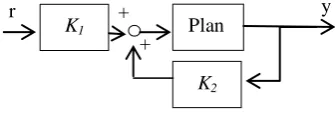
The 2DOF H infinity control is a method which can combine both time and frequency domain specifications into a single index, called stability margin. The 2DOF H infinity control consists of a feed-forward or pre-filter controller, K1, and a feedback controller, K2. In considering the loop shaping design, Gs is co-prime factor of the shaped plant [6]
which consists of a nominator factor, Ns, and a denominator factor, Ms. Fig. 3 illustrates the uncertainty model of the system and the robust control of systems.
A loop shaping system can be described in the following equation.
Gs=GW1=Ms
-1
Ns (5)
Equation (6) is accomplished with the uncertainty in the system, and it can be shown as the following equation.
G∆=(Ns+∆Ns)(Ms+∆Ms)-1 (6)
G∆ is the uncertain system.
∆N is the uncertain transfer function of the nominator.
∆Ms is the uncertain transfer function of the denominator.
|∆Ns, ∆Ms|∞ ≤ ε (7)
ε is stability margin.
Fig. 3 the uncertainty model in co-prime factor
It is well known that the controller from the conventional H infinity control has high order, and normally the high order controller cannot be implemented easily in practice [1]. To solve this problem, the proposed technique formulates the fixed structure control in the 2DOF H infinity control and loop shaping design problem, and searches the parameters by genetic algorithm.
Fig. 4 2 DOF control is fixed-structure controllers.
The fixed-structure robust 2DOF control with H∞ loop
shaping is the proposed control which the structures of the controllers are able to be specified. The design procedures of this method are summarized as follows [1].
Step 1 The structure of Tref, W1, K1 and K2 is selected as:
(8)
(9)
(10)
Step 2 Reference model (Tref) is designed to identify the desired time domain of the closed loop system and this technique uses to select the ratio between the desired time and robust performance. The range of is from 0 to 1. If
, the 2DOF and H infinity control become the 1DOF and H infinity control. Calculating the εopt shows in (11) e
y u
+
∆Ns
Ms-1
∆Ms Ns + + + + + _ + _ K1 K2 Plan t + +
r y
K1
[image:2.595.336.504.434.491.2]
(11)
K1 and K2 are synthesized by solving this inequality equation.
(12)
Finally, is computed by
(13)
Wo = 1, and K1 and K2 are the synthesized controllers.
Step 3 Genetic Algorithm searches the control parameters of K1, K2, and W1simultaneously.
B. The Fixed structure and1DOFcontrol with H∞ loop
shaping [2]
The fixed structure and 1DOF control with H∞ loop
shaping are a technique, using GA, [7]. Following steps are used for this method design.
Step 1 The structure of W1, KPID is selected as.
(14)
(15)
Step 2 Genetic Algorithm searches the parameters of K1 and W1 simultaneously. Thus, the system is robust and obtains the specified performance at the same time.
(16)
[image:3.595.313.539.86.405.2]By
Fig. 5. 1DOF control
IV. TESTING SYSTEM AND EXPERIMENTAL RESULTS
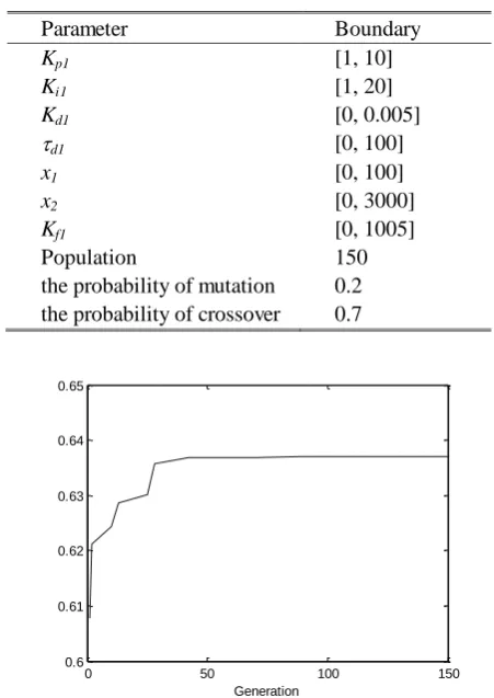
When the plant is identified by the OE system identification at the operating speed, 380 rpm, the 2DOF controllers, K1, K2 and weighting function are searched by the Genetic Algorithm. The reference model is selected as (17). In the Genetic Algorithm, the boundaries of parameters are selected as shown in Table 1 and the result of convergence of the solution is obtained as shown in Fig. 6.
TABLE 1. THE PARAMETERS OF GENETIC ALGORITHM OPTIMIZATION AND THE BOUNDARY OF CONTROL OPTIMIZATION PROBLEM FOR ROBUST 2 DOF CONTROL
Parameter Boundary
Kp1 [1, 10]
Ki1 [1, 20]
Kd1 [0, 0.005]
d1 [0, 100]
x1 [0, 100]
x2 [0, 3000]
Kf1 [0, 1005]
Population 150
the probability of mutation 0.2 the probability of crossover 0.7
0 50 100 150 0.6
0.61 0.62 0.63 0.64 0.65
[image:3.595.315.538.98.341.2]Generation
Fig. 6. The stability margin from genetic algorithm for robust 2 DOF control The resulting controllers from the presented method and conventional method are shown in Table 2. In addition, the weights and controllers can be demonstrated in Table 2.
TABLE 2. THE WEIGHTS, CONTROLLERS AND STABILITY MARGIN OF THE PROPOSED CONTROL AND 1DOF CONTROL
1DOF control 2DOF control
Weighting function
Controller
Stability
margin 0.481 0.635
Fig. 7 shows the step responses of the presented controller and the robust 1DOF controller, compared with the reference model.
PID Plant -
+ r +
[image:3.595.302.562.510.683.2] [image:3.595.51.286.525.633.2]Step Response Time (seconds) A m p lit u d e
[image:4.595.317.543.42.319.2]0 0.05 0.1 0.15 0.2 0.25 0.3 0.35 0.4 0.45 0 0.2 0.4 0.6 0.8 1 1.2 1.4 PID controller Proposed controller Reference model
[image:4.595.69.289.57.207.2]Fig. 7. Step response of control
TABLE 3. THE COMPARISON OF TIME DOMAIN PERFORMANCE OF THE DC MOTOR SPEED CONTROLS.
Settling time (s) Rise time (s) Overshoot (%) Proposed controller
0.181 0.0992 0
1DOF controller
0.133 0.0625 0
Reference model
0.196 0.1097 0
(17)
Table 3 shows the simulation results of step responses from the proposed controller and the 1DOF controller. The response of the proposed controller is close to the reference model, but that of the1 DOF control is much different to the desired response.
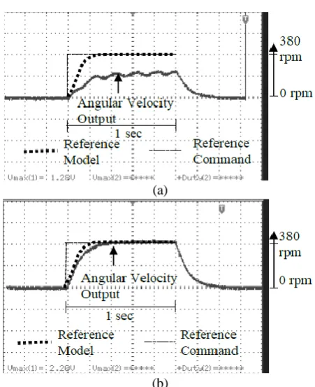
The proposed and 1DOF controllers were also tested in the real DC motor speed control system. The results of step responses of the proposed controller and the 1DOF controller indicate that the overshoot is not presented in the step responses of both methods, and the settling time of the proposed controller is close to that of the 1DOF method. The robust performance of the DC motor system was verified by taking the different payloads to the system, which increases the torque load on the system. The loads were increased from 0 kilograms to 16 kilograms. The experimental results indicate that the proposed controller obtains high performance and well robustness. The results shown in Fig. 8(a) and 8 (b) are the responses at the system load 16 kilograms. Clearly, the robust performance of proposed controller is better than that of the 1DOF controller. There is a large steady state error and oscillation in 1DOF control response.
(a)
(b)
Fig. 8. The step responses of both controllers at 16 kilograms load (a) 1DOF controller and (b) the proposed controller
TABLE 4. THE DYNAMIC RESPONSES OF THE PROPOSED CONTROLLER AND 1DOF AT VARIOUS LOADS IN REAL ON DC
MOTOR SYSTEM.
Weight( kg)
The proposed controller The 1DOF method
Rise time (s) Settling time (s) Steady state error (%) Rise time (s) Settling time (s) Steady state error (%)
0 0.23 0.43 0 0.29 0.47 0
2 0.23 0.43 0 0.29 0.47 0
4 0.23 0.43 0 0.29 0.47 0
6 0.23 0.43 0 0.29 0.47 0
8 0.23 0.43 0 0.29 0.47 0
10 0.23 0.43 0 0.32 0.5 31
12 0.23 0.43 0 N/A N/A 36
14 0.23 0.43 0 N/A N/A 42
16 0.23 0.43 0 N/A N/A 49
V. CONCLUSION
[image:4.595.42.296.253.397.2] [image:4.595.303.558.393.574.2]changed from the nominal condition. In contrary, the performance of the 1DOF controller is deteriorated by large steady state error and oscillations.
ACKNOWLEDGEMENTS
This work was supported by the King Mongkut’s Institute of Technology Ladkrabang under the research grant no. KREF055706 and also by doctoral student scholarship under the Research and Reseacher Industry (RRi), the Thailand Research Fund (PHD5810091).
REFERENCES
[1] Nuttapon Phurahong, Somyot Kaitwanidvilai and Atthapol Ngaopitakkul, “Fixed Structure Robust 2DOF H-infinity Loop Shaping Control for ACMC Buck Converter using Genetic Algorithm,” IMECS, vol. 2, pp. 1030-1035, 2012.
[2] S. Kaitwanidvilai, P. Olranthichachat and Manukid Parnichkun, “Fixed Structure Robust Loop Shaping Controller for a Buck-Boost Converter using Genetic Algorithm,” IMECS, vol. 2, pp. 1511-1516, 2008. [3] N. Chitsanga and S. Kaitwanidvilai, “Robust 2DOF fuzzy gain
scheduling control for DC servo speed controller," IEEJ Transactions on Electrical and Electronic Engineering, vol.11 no.6, 2016.
[4] B. C. Kuo, Automatic Control Systems. New Jersey: Prentice Hall, 1995.
[5] Ljung L., System Identification: Theory for the User 2nd edition. New Jersey: Prentice-Hall, 1999.
[6] McFarlane Duncan and Glover Keith, “A loop shaping design procedure using H∞ synthesis,” IEEE Transactions on automatic
control, vol. 37, no. 6, pp. 759-769, 1992.
[7] S. Kaitwanidvilai and M. Parnichkun, “Genetic algorithm based fixed-structure robust Η∞ loop shaping control of a pneumatic servo system,”