Abstract—Hydroelectric power, one of the most important sources of mass generation of electric power, is a renewable source of energy. The amount of electricity that can be produced by a hydro-electricity generating system depends on systemic variables viz; plant efficiency, volumetric water flow through the turbine and the head of the water from the water surface to the turbine. The availability of the Water in the reservoir is a function of some hydrological variables principal among which are rainfall, reservoir inflows and evaporation. Understanding the dynamics of these variables, and the correlation between them are core to proper planning and management of a hydroelectric power station. In this Study, simple mathematical methods that include linear programming and statistical analysis based on simulation techniques were used to evaluate vital parameters based on the hydrologic data obtained from the Hydrologic Units of the Shiroro Power Stations in Nigeria. The overall aim of the study is to idealize power generation at Shiroro dam in and out of rain season so
as to ensure optimum generation of electricity all year round in order to achieve energy sufficiency in Nigeria.
Index Terms—hydroelectric power, pumped storage,
hydrological variables, simulation techniques.
I. INTRODUCTION
N Nigeria almost every human endeavour has been paralyzed. A major factor that has reduced the standard of living of an average Nigerian to near zero is the epileptic supply of electric power. Government policies formulated at different times to curb the unfortunate trend were of no effect. To this end, 90% of factories in the manufacturing sector are moribund. The sporadic supply of power in Nigeria affects every sphere of human endeavour; from all forms of domestic discomfort to national embarrassment. For instance there was a three hour power outage at the Muritala Mohammed International Airport in Ikeja, Lagos on Sunday the 9th day of May, 2010 and the ugly incidence was repeated on Tuesday the 11th of May of the same year. Power supply situation in Nigeria has no doubt affected the economy of the nation negatively in no small measure. Basically, the power generated at an hydroelectric power plant results from the kinetic energy that produce the torque obtained from the mass of water that falls through the height, h; the differential of head of water from the inlet point H1, and the head of water above the turbine H2. Hence
Manuscript received March 6, 2017; revised March 14, 2017. Optimizing Hydroelectric Power Generation: The Case of Shiroro Dam.
Olawale Olaniyi Emmanuel Ajibola is with the University of Lagos, Akoka, Yaba, Lagos 23401 Nigeria (phone: +234-802-302-5053; e-mail: [email protected]).
Olamide Sherifah Ajala is with Centre for Applied Dynamics, School of Engineering, University of Aberdeen. (e-mail: [email protected]). James O. Akanmu is with the University of Lagos, Akoka, Yaba, Lagos 23401 Nigeria (e-mail:[email protected]).
Oluwaseyi Jessy Balogun is with the College of Medicine of the University of Lagos, Akoka, Yaba, Lagos 23401 Nigeria (e-mail: [email protected]).
2 1 H
H
h . The process of conversion involves a hydraulic turbine which converts the kinetic energy of the flowing water into mechanical work that produce a torque. A dynamo then converts the torque thus produced into electricity. The operation of a generator is based on Faraday’s principle of electromagnetism. Faraday propounded that when a magnet is moved past a conductor, it causes electricity to flow in the conductor. In a large generator, electromagnets are made by circulating direct current through loops of wire wound around stacks of magnetic steel laminations. These are called field poles, and are mounted on the perimeter of the rotor. The rotor is attached to the turbine shaft, which rotates at a fixed speed. When the rotor turns, it causes the field poles (the electromagnets) to move past the conductors mounted in the stator that causes electricity to flow and develop potential difference across the generator output terminals [1]. Hydro electric power generation thus produced is computed from the mass of water that flows through the Turbine based on the release from the reservoir and constrained by the Turbines flow capacity [2]. The volume of water that passes through the Turbines is bounded by maximum and minimum Turbine flow. If there is too much water, excess water is released through spillways which do not contribute to the generation of electricity. If however the release is less than the minimum Turbine flow then no electricity is generated. Therefore the amount of electricity that can be generated at hydroelectric plant is dependent upon two factors, [3]. These factors are:
(1) The vertical distance through which the water falls usually refers to as the Head and
(2) The rate of flow of water (m3s-1).
Thus the quantity of electricity produced is proportional to the product of the head and the rate of the flow. Accurate quantification of the reservoir content and adequate knowledge of reservoir operating policies is paramount to ensure optimal storage of water in the reservoir when managing production of hydroelectric energy. Climatic conditions affect both the availability and reliability of the water stored in reservoirs. To this end, optimum management of such reservoirs is very important under different climatic uncertainties [4, 5].
II.THRORETICAL CONSIDERATIONS
This section contains an elucidatory consideration of the theories and guiding policies upon which the systematic build–up of the models and solution contained therein are based. System Dynamics (SD) is a method for understanding the dynamic behaviour of complex systems [6]. The SD procedure includes: defining and identifying a problem, analyzing the problem, identifying possible
Optimizing Hydroelectric Power Generation:
The Case of Shiroro Dam
Olawale O. E. Ajibola, Olamide S. Ajala, James O. Akanmu and Oluwaseyi J. Balogun, Member, IAENG
solution, developing an algorithm, selecting the best solution, evaluating the solution and implementing this solution.
Some of the characteristics of SD methodology which makes it suitable for this work include:
i.Understanding the problem situation: The purpose is to clearly identify the problem and its causative factors as well as the relationships between them;
ii.Explicit conceptual model and simulation model building: a sign causal diagram is drawn in order to develop the understanding of influence of the variables on each other. Explicit concepts of SD such as flows, levels and auxiliary are used in simulation model building process; iii.Simulation and gathering the results: after building the simulation model, it is then possible to analyze different scenarios for different policies
An over view of a hydro-electric power plant indicates that: a) Hydro-electricity generators converts the kinetic
energy of the falling water into electrical energy by using uninterrupted flow of water in motion to turn a Turbine connected to an electric generator.
b) The amount of electricity that can be produced by hydro-electricity generating system depends on the plant efficiency, volumetric water flow through the turbine, and the head of the water from the water surface to the turbine
Therefore the most important hydrological data required for hydropower studies are the long term reservoir inflows records that represent the flow variable for power production. Others includes rating curves, reservoir storage elevation, evaporation loss and other types of losses, sedimentation, water discharge data and downstream requirement [7]. The principle of hydroelectric power generation is based on the law of conservation of energy where kinetic energy that resulted from the movement of the mass of water from the river is translated to stored energy which in turns exacerbates the build-up of the kinetic energy that turns the turbine and ultimately produces electricity in Figure 1 [5].
The total power output P, that can be generated from water in hydroelectric power plant is directly proportional to the height h of water from the inflow to the turbine and the rate, r of flow of water. Thus:
rh
P (1)
Pgrh (2)where g is the acceleration due to gravity (usually, g = 9.81 m2s-1).
If the head of water translates to release, then higher volume of water in the reservoir will translate to higher quantity of electricity produced by the hydroelectric power (HEP) plant [8, 9]. To maximize HEP therefore the head of water (HoW) in the reservoir must be adequately high such that the difference between the HoW and the turbine must be at premium so that the kinetic energy produced by the mass of water will be adequate to produce the require torque that will generate expected power output. The maximum height of water is fixed by natural factors like the height of river bed, the amount of water involved and other environmental factors. The location of the power generation unit can be adjusted based on the maximum total power output that would be generated. Usually the power generation unit is located at levels lower than ground level
so as to get the maximum head of water. The total flow rate of water can be adjusted through the penstock based on the design requirements [10].
A. The Pumped Storage Phenomenon
Pumped-Storage is a well-known technology evolving from the Hydro-Electric family of power plants. About 300 projects are in operation all over the world, with a total installed capacity of 83,000 MW. Currently, several tens of similar projects are under construction. Pumped-Storage stores excess electricity generated during times of low demand (such as night periods) and plunges it back to the system by pumping back the used volume to attain fresh water head which is in turn used to turn the turbine when demand is high [11]. Its immediate response prowess lead to the performance of expected functions such as: load regulation, spinning reserve, frequency and voltage regulation, load and dispatch management, all of which are referred to as dynamic benefits. It is friendly to the environment, with no emissions of pollutant [11, 12]. The unique characteristics of Pumped-Storage made it viable in most developed and developing countries ([13].
Pumped storage hydroelectricity option is a method of producing electricity stored for usage when demand is at its peak [14]. At times of low demand for electricity, excess electrical energy generated is used to pump water into an elevated reservoir for usage during peak period when the stored water is released back into the lower reservoir via a turbine, thereby generating more hydroelectricity. About 70% of the additional electrical energy is thus generated over and above the capacity of the original energy produced by the same volume of water where conventional hydroelectric system is used as currently done in Shiroro dam [15]. To cut cost, some facilities use abandoned mines site as the lower reservoir. Many other facilities use the natural height difference between two natural bodies of water such as expanded lake or artificial reservoirs [16].
Pumped storage hydro-electricity works on a very simple principle. Two reservoirs at different altitudes are required (one above the turbine, the other below it). When the water is released, from the upper reservoir, energy is created by the down flow which is directed through high-pressure shafts, linked to turbines. In turn, the turbines power the generators to create electricity. To achieve this feat, water is pumped back to the upper reservoir by linking a pump shaft to the turbine shaft using a motor to drive the pump. The pump motors are powered from the energy generated by the hydroelectric system. However, the gains of the process can be obtained from the efficacy and the efficiency derivable from the recurrent process. A dynamic response involving generating units of the system can achieve maximum output, usually, within 16 seconds of their operation. Pump storage generation offers a critical back-up facility during periods of excessive demand on the national grid system.
In recent time, research efforts have been directed
towards the development of reverse-engineered
(PAT) is at least 50 percent less or even lower than that of a comparable turbine. However, for adequate performance, a micro-hydropower site must have a fairly constant head and flow because PATs have very poor partial-flow efficiency. It is possible to obtain full efficiency from PATs by installing multiple units, where they can be turned on or off depending on the availability of water in the stream. PATs are most efficient in the range of 13 to 75 m (40 to 250 ft.) of gross head. The higher the head, the less expensive the cost per kilowatt; this is generally the case with all turbines [17].
[image:3.595.46.293.184.344.2]Source: Ulowa Wiki
Fig 1 : Schematic of pumped storage power plant
TABLEI
SUMMARYOF EFFICIENCY OF VARIOUS PUMPS
Impulse turbines
Prime Mover Efficiency Range Pelton
Turgo Cross-flow
80-90% 80-95% 65-85% Reaction turbines
Prime Mover Efficiency Range Francis
Pump-as-turbine Propeller
Kaplan
80-90% 60-90% 80-95% 80-90% Water wheels
Prime Mover Efficiency Range Undershot
Breastshot Overshot
25-45% 35-65% 60-75%
The difference between the level of the upper and lower reservoir is the head, for very high head it is necessary to use multistage pumps. However, for large installations with one stage pumps, a head in the range of between 300 and 600m is required. For instance, 4 million cubic meter reservoir capacity is required to produce 1000 MW in four hours at 400 m head. Seasonal storage reservoirs may require a capacity larger than one billion cubic meters to sustain pumped storage that will last the season. A pumped storage station costs in excess of US$2500/kW and the overall losses are about 25%. Most pumped storage stations store sufficient water for 6-10 hours of operation [18]. The efficiency of the system depends on the length and design of the hydraulic subsystems and machinery, especially the reversible units of the pump turbines or separate pumps and turbines. Usual efficiency ranges between 70 – 80% for the pumping/production. Main Functions of pumped storage hydroelectric system are:
i.Only solution for efficient and cost effective means of storing large amounts of energy
ii.Acts as a quick response for peak load energy supply iii.Provide ancillary services (network frequency &
voltage regulation, reserve capacity, black start capability, reactive power production)
Fig 2: Overall pumped-storage system model
And the advantages include:
i.Increase in profitability for plant owners in volatile electricity spot markets
ii.Allowance of optimization of global operations of power plant fleets and electrical network infrastructures iii.Has higher global cycle efficiency compared to other
large storage solutions (approximately 80%)
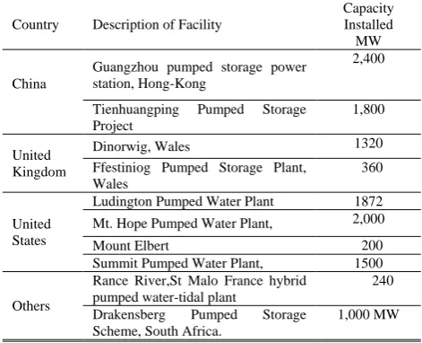
iv.Has a positive environmental impact by enabling increased use of renewable energy sources [18]. The statistics of pumped storage plants worldwide is as summarized in Table 2 below:
Table 2
Global pumped-storage plants statistics
Country Description of Facility
Capacity Installed MW
China
Guangzhou pumped storage power station, Hong-Kong
2,400
Tienhuangping Pumped Storage Project
1,800
United Kingdom
Dinorwig, Wales 1320 Ffestiniog Pumped Storage Plant,
Wales
360
United States
Ludington Pumped Water Plant 1872 Mt. Hope Pumped Water Plant, 2,000
Mount Elbert 200
Summit Pumped Water Plant, 1500
Others
Rance River,St Malo France hybrid pumped water-tidal plant
240
Drakensberg Pumped Storage Scheme, South Africa.
[image:3.595.308.544.581.772.2]The basic equation that relates release with energy produced in an hydroelectric system is given by:
n H R
kWHt 2725 t t (3)
where
R
t is the release into the penstock in Mm3,H
t is head in meters and n is efficiency.A biometric analysis of the data supplied by Shiroro dam management for average turbine flow and inflow revealed incoherent correlation which failed to make a categorical statement about the truth of its empiricism and therefore cannot be applied in any serious scientific research work upon which the fate of such an important magnitude as the power generation project could be based. We have randomly selected July 23 of each year under consideration. Table 3 revealed a major anomaly in the structure of the data selected through stochastic process from the pool of the aforementioned data. A close study shows that in 2003 for instance release is greater than inflow. The chart in Figure 3 presents a more expository revelation of our claim.
TABLE 3
RECORDS OF INFLOW, RELEASEAND POWER
GENERATED IN SHIRORO DAM (1990 AND 2004)
YEAR INFLOW PGN(MW)X10^3 RELEASE 2004 72929.1 242.5629 115879.2 2003 103025.7 253.8834 116120.9 2002 82580.84 218.8941 101550.9 2001 84914.1 267.5201 122366.5 2000 77394.03 257.1351 102406.1 1999 93149.9 209.7861 105938.4 1998 81361.84 214.1446 107417.4 1997 83817.42 223.0044 103589.6 1996 77454 201.9469 95395.35 1995 55352.16 194.4828 90808.48 1994 81935.19 204.794 96428.16 1993 73861.74 211.9957 97810.77 1992 80755.34 230.0002 108718.6 1991 73541.35 199.7155 90598.74 1990 73343.42 215.26887 97404.26
Based on these observations it is obvious that the data provided in Shiroro dam cannot be relied upon, hence the need for simulation of data. Equations (12) to (20) were solved through the software named TORA, eight iterations were performed. The storage k of the reservoir is been varied and the result is as tabulated in Table 3 in the appendix.
III. METHODOLOGY
Reservoir operation is an important element in water resources planning and management. It consists of several control variables that defines the operation strategies for guiding a sequence of releases to meet specific demands of the stakeholders with different objectives, such as flood control, hydropower generation and allocation of water to different users. A major difficulty in the operation of reservoirs is the fluctuation in storage. Therefore, it is necessary to optimize reservoir operation in determining adequate water storage for generation of hydropower, [19, 20, 21, 22].
Of concern in this work is the uninterruptable supply of water resources into the reservoir to ensure adequate supply
of water for the purpose of generating electricity from a hydroelectric system all year round, especially during drought and dry season. To this end, pumped storage may be introduced in the hydropower plant to facilitate an efficient recycling of the available water resources at these periods of the year. According to the U.S department of the Interior Bureau of Reclamation Power Resources Office, July 2005, demand for electrical power supply varies greatly during the day and night. These demands vary considerably from season to season. In other to maximize storage so as to ensure constant electrical power supply, it is necessary to find a way of recycling the water used to turn the turbine [23]. Hence a pumped storage, the basic principle of which entails that the release from the reservoir is pumped to a storage tank where it can be used to return the turbine during the period of drought, thus ensuring constant supply of electricity the year round.
Optimization models are based on clearly defined goals (objective functions), criteria for evaluation of control decisions, and constraints as limitations during optimization [24, 25, 26, 5]. In our own case, it is enough to maximize storage so that the Shiroro Hydroelectric power plant will have adequate water supply the year round. The typical constraints in a reservoir optimization model, including conservation of mass and other hydrological and hydraulic constraints, minimum and maximum storage and release, hydropower and water requirements as well as hydropower generation limitations, are presented as follows:
i.Hydraulic constraints are defined by the reservoir continuity equation.
t St It Rt Et t TS 1 1,2,, (4)
Where S
t1 is storage at time step t1; S
t is storage at time step t; I
t is the reservoir net inflow at time step t (including reservoir inflow, precipitation and evaporation); R
t is the reservoir outflow at time step t, E
t is the evaporation loss at time step t corresponding to the water spread area at the average storage
S
t S
t1
2. T is the total number of time steps in the period under consideration.ii.Constraints on discharge defined by maximum and minimum permissible reservoir releases:
t R t nR
Rmin max 1,2,, (5) iii.Constraints on storages defined by maximum and
minimum permissible reservoir storages:
t S t nS
Smin max 1,2,, (6) iv.Constraints on elevations defined by maximum and
minimum permissible level at specified sites:
t h t nh
hmin max 1,2,, (7) v.Constraints on hydropower generations defined by
maximum capacity and minimum requirement of hydroelectricity:
t H t nH
Hmin max 1,2,, (8) HP(t) is a nonlinear function of S(t) and R(t).
vi.Energy production, expressed as the energy production capacity (EPC):
t Ht Ht t nREQ C
where C is the conversion factor for potential to electrical energy, H is the average head over turbine and η is the energy plant efficiency.
vii.The energy that can be produced is restricted by the plant capacity (PCAP) and number of hours available for energy production (NHP). Thus, the maximum peak energy produced (MPEP) is:
t PCAP
t NHP
t t nMPEP ** 1,2,, (10)
The energy produced at any time t is:
t
TEP
t MPEP
t
t n PKE min , 1,2,, (11)where PKE is the peak energy produced and TEP is the total energy that can be produced at a particular time. One of the problems associated with the operation of the reservoir is the operational and release policy adopted. At Shiroro reservoir, annual flooding of lower Niger plains occurs when the spillways are opened in September during high inflows. While during the period of low inflows (March to May), head of water in the reservoir is often below the desired level. Operation of reservoirs is based on experience of the water managers. A viable resolution of these anomalies may therewith be found with the proposed optimization technique which employs the recycling of released Rt as the inflow of the reservoir [11]. A. Optimizing the Reservoir’s Operation From literature, the energy production capacity (EPC) is more than often, a function of storage [27, 28]. However storage at time t is determined by the inflow of water and storage at time t is determined by the inflow of water and the storage at time (t-1) when a discretized variable is used. It therefore follows that the EPC can be wholly determined by the storage of the reservoir. Hence, to maximize EPC output is tantamount to maximizing storage. The objective function for the reservoir optimization process is simplified thus: Maximize
T t t I t S 1 (12)Subject to: S
t1S
tItRtlt 0 (13)R
t It 0 (14)S
t1k (15)I
t 0.7R
t K (16)l
t0.3R
t0 (17)R
t K (18)I
t 0,R
t 0,S
t 0,.l
t 0 (19)Smin SmaxK (20) n
, 1,2,
t
where, St+1 is the final storage at time t; Stis the storage at
the beginning of the period t; K is the storage capacity of the reservoir; Rt is the release at time t; lt is the total loss at time
t while It is the inflow at time t.
Equation (13) is the reservoir continuity equation, while equation (14) is implemented to account for the recycling of the release used to turn the turbine. The flowchart for the methodology is as shown in Figure 2.
B. Reservoir’s Inflow and Release Statistics
This section provides the summary of the statistics obtained from the various analyses made using the approach adopted in the preceding section. Table 4 is a collection of the statistical parameters used as decision variables for our analyses. The figure below shows the graph of inflow and release from the reservoir against years under consideration, from the graph, it can be perceived that from January to May of these years the release is comparatively greater than inflow while from June to August of the same period the inflow is appreciably greater than the release. This shows that an extra storage must be somewhere around the downstream to make-up for the shortfalls in the release from January to May to optimize the hydroelectric power generated for these months. To this end, a pumped storage becomes a viable solution to the irregularity observed in the data.
Despite many devoted effort to correctly forecast rainfall and run off, rainfall prediction still remain problematic. Rain is a form of precipitation. It is the water that falls from the cloud to the ground through hydrological cycle. The radius of a drop of rain is slightly greater than 250 µm. The pattern and invariably the amount of rainfall are among the most important factors that affect the output of hydroelectric power generating systems [29].
Statistical observation obtained from pattern of these systems are precipitation dependent Rainfall are essential and are indeed fundamental to understanding the rainfall runoff process; therefore the accuracy of the rainfall data at some critical point is very important and significant to any specific use a set of data is applicable to. Subsequent paragraphs enumerate the import of main results of the evolving analysis of the record of rainfall at Shiroro hydropower stations during the period under consideration. The onus here is:
TABLE 4
RECORDS FROM PATTERN OF RAINFALL INTO SHIRORO
DAM BETWEEN 1990 AND 2008
YEAR MEAN (mm) MEDIAN STDV MAX
2008 88.2 28.9 115.5663 305.7 2007 119.916667 83.55 126.3198 332.3 2006 128.075 78 150.0853 425
2005 92.2083333 64.15 103.347 247.1
2004 85.025 44.45 96.8482 236.4
2003 110.058333 88.35 120.0423 351.5
2002 97.325 77 106.2391 286.6
2001 112.116667 78.85 128.6778 360
2000 102.625 95.2 114.6116 364.7
1999 113.1 73.5 131.1867 410.7
1998 104.591667 86 110.0194 280.8
1997 143.425 122 152.9154 473.2
1996 103.575 66.25 112.3733 307.2
1995 100.35 54.85 133.3404 443.8
1994 98.125 66.6 107.1328 264.7
1993 114.533333 50 138.5029 377.7
1992 120.2 107 125.7707 368.1
1991 113.191667 29.95 148.9809 450.3
a.To analyze a record of rainfall for the purpose of establishing trends or pattern of changes observed. b.To demonstrate the direct method of analyzing rainfall
data that can be used for purpose of planning future power generation output.
In this paper, Microsoft excel software statistical package is used to analyze the Rainfall regime. The average annual rainfall in respect of Shiroro power project is 1325.213 mm with the highest rainfall record of 1749.3 mm in 1990 while the lowest record of 617.4mm was observed in 2008. The statistical measures of taken mean, maximum, minimum, the standard deviation and coefficient of variation of the annual rainfall for the station is shown in Table 4 while the summary of the statistics are presented in Table 5 .
IV. DISCUSSION OF RESULTS
[image:6.595.310.547.91.200.2]Reservoir inflow observation is one of the most reliable methods of estimating the runoff yield. Understanding reservoir flow pattern is therefore fundamental to achieving outstanding success during the process of monitoring of water budget in a reservoir. We are required to know the lowest dependable flow on one hand and the highest flood level possible in the river on the other hand. The former is useful in the design of various components for proper optimization of water resources while the latter provides information of flooding which the structure will have to curtail [30, 31]. The flow rate of a river usually refers to the volume of water that passes through a section of the river in a unit time in m3/sec [32, 33]. The average annual turbine discharge by analysis at Shiroro is 9303.4m3/sec between 1990 and 2004, with Maximum turbine discharge of 12412m3/sec occurring in 2001. Figure 3 below shows the relationship between the inflow and the release from the reservoir for the years under consideration,
Fig 3: Inflow and the release from the reservoir for 1991-2007
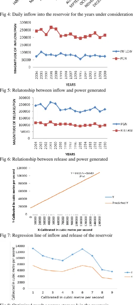
The graph showing daily variation of reservoir inflow for the years under consideration is described by Figure 4. A verification of the relevance of inflow information to the development of a viable model for optimization process for hydropower system is presented in figure 5 while figure 6 is a direct implication of figure 5 since ideally release is proportional to inflow into the reservoir. The Biometric analysis of the inflow/release relationship in the case of
Shiroro hydropower project can be summarized by observing a linear relationship using regression analysis. This is presented in figure 7.
[image:6.595.305.532.187.703.2]Fig 4: Daily inflow into the reservoir for the years under consideration
Fig 5: Relatonship between inflow and power generated
Fig 6: Relationship between release and power generated
Fig 7: Regression line of inflow and release of the reservoir
Fig 8: Optimized result z versus storage k in the reservoir
The regression analysis for the inflow and release of the reservoir was carried out using MS-Excel graphics. The release when there is no inflow as predicted by the regression line is 16583 while the rate of change of release with respect to inflow (slope) is 0.6117. Thus the equation as shown in the graph describes the variation of annual TABLE 5
INFLOW/RELEASEFOR SHIRORO POWER PROJECT SUMMARY STATISTIC
CORREL COVAR SLOPE MEAN STDV RELEASE
(1990-2007)
INFLOW
[image:6.595.309.532.221.470.2] [image:6.595.41.297.245.312.2] [image:6.595.50.285.563.684.2]reservoir inflow for various years. Figure 8 above depicts the relationship between the optimized result and the storage in the reservoir at anytime t and it can be inferred from the graph that there is a perfect correlation between z and k, that is for every increase in storage value there is a corresponding increase in the optimized result which shows that the linear program employed in the solution is consistent with the result of our analysis.
V.CONCLUSION
In the paper, we have proposed a new but simplified method for improving the efficiency and by implication, the production output of hydroelectric power generation at Shiroro dam especially during the period of drought. This work employs optimization models to explore viable engineering solution options thereby enriching the literature with the ultimate goal of arresting the tetra-headed monster that is responsible for the incessant power failure that has plagued the life of an average Nigerian for decades now. And it is our belief that our proposed model may reduce economic discomfort and curb colossal waste currently incurred both by the citizenry and government due to the inadequacies in the power sector of the economy. It may also lead to improved technological knowhow if properly harnessed in order that our collective efforts towards achieving Nigeria’s developmental goals may come to fruition.
REFERENCES
[1] H. Perlman, 2010. Hydroelectric power: how it works. http://ga.water.usage.gov/edu/hyhowworks.html.
[2] H., Madsen, 2003, Parameter estimation in distributed hydrological catchment modelling using automatic calibration with multiple objectives. Advances in WaterResources 26(2): 205-216.
[3] M. Karamouz 2003. Resources system analysis. Lewis Publisher. Washington, D.C. pp. 441-484.
[4] R. E. Rosenthal, 1981. A Nonlinear Network Flow Algorithm for Maximization of Benefits in a hydroelectric Power system” Operational Research, Vol. 29, No. 4, pp 763-786.
[5] C. Revelle, 1999. Optimizing reservoir resources: including a new model for reservoir reliability. John Wiley & Sons, Inc.pg 45-64 [6] J. W. Forrester, 2009. Some basic concepts in system dynamics. Sloan
School of Management, Massachusetts Institute of Technology. UK. [7] Mays, L. W. and Tung, Y. K., 2002, Hydrosystems Engineering and
Management. Water Resources Publications.
[8] US Power Resources Office 2005. Hydroelectric power: managing water in the west. Bureau of Reclamation, Power Resources Office, US Department of the Interior. USA.
[9] T. Olaoye, T. Ajilore, K. Akinluwade, F. Omole and A. Adetunji, 2016. Energy Crisis in Nigeria: Need for Renewable Energy Mix. American Journal of Electrical and Electronic Engineering, 2016, Vol. 4, No. 1, 1-8.
[10] S. Vedula and P. P. Mujumdar, 2005. Modelling techniques and analysis. Tata McGraw-Hill Publishing Company limited. New Delhi. [11] W. Yeh, 1985, Reservoir management and operations models: A
state-of-the-art review. Water Resources Research 21(12): 1797-1818. [12] Y. M. Suleiman and I. P. Ifabiyi 2014. The role of rainfall variability
in reservoir storage management at Shiroro hydropower dam, Nigeria. An International Journal of Science and Technology. Vol. 3(2), No 7, pp. 18-30
[13] A.K. Jha, R. Bloch, and Lamond, 2012. Cities and flooding: a guide to integrated urban flood risk management for the 21st century. The World Bank, Washington.
[14] M. V. F. Pereira and L. Pinto, 1985. "Stochastic Optimization of a Multireservoir Hydroelectric System - a Decomposition Approach." Water Resources Research 21(6): 779-792.
[15] J. O. Akanmu, 2007; Model for the optimal operation of shiroro reservoir, PhD thesis. University of Lagos, Akoka. Nigeria.
[16] X. Yang, E. Parent, M. Claude, and P.-A. Roche, 1995. Comparison of real-time reservoir-operation techniques. Journal of Water Resources Planning and Management 121(5): 345-351.
[17] P. O. Yapo, H. V. Gupta, and S. Sorooshian, 1998. Multi-objective global optimization for hydrologic models. Journal of Hydrology 204: 83-97.
[18] L.A. Fodstad, 2009. Pumped storage. Risoe.dtu.dk/en/…/ storage/lars_fodstad_ tilladelsa.ashx
[19] U. Karaagac, J. Mahseredjian, S. Dennetière, 2009. Modelling and Simulation of the Start-up of a Pumped Storage Power Plant Unit, International Conference on Power Systems Transients Kyoto, Japan. [20] A. B. Adegbehin, Y.O. Yusuf, E.O. Iguisi, and O. D. ZubairuJimoh,
2016. Reservoir inflow pattern and its effects on hydroelectric power generation at the Kainji Dam, Niger State, Nigeria. WIT Transactions on Ecology and the Environment, Vol 203; pp. 233 – 244.
[21] A. B. Adegbehin, 2016. Effects of some weather parameters and reservoir inflow pattern on hydroelectric power generation in kainji dam niger state, Nigeria. M.Sc. Dissertation. Ahmadu Bello University, Zaria, Nigeria.
[22] I. Duranyildiz, B. Onoz and M.Bayazit, 1999. A Chance-Constrained LP Model for Short term reservoir Operation Optimisation. Turkish Journal of Engineering and Environmental Science 23: 181-186. [23] J. Labadie, 2004. Optimal operation of multireservoir systems:
state-of-the-art review. Journal of Water Resources Planning and Management © ASCE pp. 111
[24] T. Akter and S. P. Simonovic, 2004. Modelling uncertainties in short-term reservoir operation using fuzzy sets and a genetic algorithm. Hydrological Science Journal 49(6):1081-1079.
[25] L. Chen, 2003, Real time genetic algorithm optimization of long term reservoir operation. Journal of the American Water Resources Association 39(5): 1157-1165.
[26] J. Kelman, J. Stedinger, L. A. Cooper, and E. Hsu, 1990. Sampling stochastic dynamic programming applied to reservoir operation. Water Resources Research 26(3): 447-454.
[27] K. Chan-Ki, K. S. Vijay, J. Gil-Soo, L. Seong-Joo, L. Seok-Jin, 2009. HVDC Transmission: Power Conversion Applications in Power Systems. John Wiley and Sons (Asia) Pte Ltd. Singapore.
[28] K. D. W. Nandalal. and J. J. Bogardi, 2007. Dynamic programming based on operation of reservoirs: applicability and limits. Cambridge University Press, UK.
[29] R. Oliveira and D. P. Loucks, 1997, Operating rules for multireservoir systems. Water Resources Research 33(4): 839-852.
[30] L. John, 2004. Optimal operation of multireservoir system: State-of-the-Art review. Water Resources Planning and Management 130(2): 93-111.
[31] T. S. Abdulkadir, A. W. Salami, B. F. Sule, J. A. Adeyemo 2015. Neural Network Based Model for Forecasting Reservoir Storage for Hydropower Dam Operation. International Journal of Engineering Research and General Science. Volume 3, Issue 5, pp.639 – 647. [32] D. P. Loucks, J. R. Stedinger and U. Shamir, 1985. Modelling Water
Resources Systems: issues and experience. Civil Engineering System Vol. 2, pp 1-9