warwick.ac.uk/lib-publications
Original citation:
Carlsson, Oscar , Vera, Daniel, Delsing, Jerker and Ahmad, Bilal (2016) Plant descriptions for
engineering tool interoperability. In: IEEE 14th International Conference on Industrial
Informatics, Poitiers, France, 18-21 Jul 2016.
Permanent WRAP URL:
http://wrap.warwick.ac.uk/79547
Copyright and reuse:
The Warwick Research Archive Portal (WRAP) makes this work by researchers of the
University of Warwick available open access under the following conditions. Copyright ©
and all moral rights to the version of the paper presented here belong to the individual
author(s) and/or other copyright owners. To the extent reasonable and practicable the
material made available in WRAP has been checked for eligibility before being made
available.
Copies of full items can be used for personal research or study, educational, or not-for-profit
purposes without prior permission or charge. Provided that the authors, title and full
bibliographic details are credited, a hyperlink and/or URL is given for the original metadata
page and the content is not changed in any way.
A note on versions:
The version presented here is a working paper or pre-print that may be later published
elsewhere. If a published version is known of, the above WRAP url will contain details on
finding it.
Plant descriptions for engineering tool
interoperability
Oscar Carlsson
Midroc Automation ABStockholm, Sweden Email: [email protected]
Daniel Vera
Fully Distributed Systems Ltd. Coventry, United Kingdom
Email: [email protected]
Jerker Delsing
Lule˚a University of TechnologyLule˚a, Sweden Email: [email protected]
Bilal Ahmad
Automation Systems Group, WMG, the University of Warwick Coventry, United Kingdom
Email: [email protected]
Abstract—The emergence and deployment of connected de-vices in many domains of application (e.g. industrial production, buildings and facilities, urban environment, etc.) have resulted in the need to achieve integration of multiple and more complex systems. This new environment is stressing the intrinsic limits imposed by monolithic standards, data models and integration methods that focus on specific domains of application, types of systems, or specific aspects of a system.
This paper describes the Plant Description Service developed as part of the Arrowhead Interoperability framework (EU EC-SEL funded project). The manuscript contains a description of the abstract system descriptive model based on which the Plant Description service was implemented, and describes how the service can be used to achieve integration of several industry standards and data models. Case studies are provided that illustrates how the service was practically implemented to support engineering scenarios in the domain of industrial production. The paper concludes with a critical review of the approach and suggestion for future work and developments.
Keywords—Industrial automation, engineering, interoperability, standards, Arrowhead.
I. INTRODUCTION
Large modern projects, such as construction of facto-ries, power plants, airports, or railroad tunnels, incorporates many engineering disciplines and contains a large number of connected devices. In such projects the engineering quickly becomes a complex operation with the need to exchange data between different tools and data sources used by engineers from different disciplines. [1]
As P´atkai et al. [2] point out, it is vital in situations where safety and performance are critical that components can be tracked throughout the complete life-cycle, including production, operation, maintenance, re-use and other possible scenarios. Using unique identifiers both for the components and for the functional and locational sections that components are associated with lowers the risk of confusion as systems or personnel from different areas or disciplines are required to cooperate and exchange information.
With end-to-end engineering, horizontal integration and vertical integration seen as overarching aspects of the German initiative Industrie 4.0 [3], [4] and with Innovative Engineering
being seen as one of the main aspects of digital technology, as perceieved by leaders in economy and society according to ITEA-ARTEMIS [5], there is support for more powerful and better integrated engineering tools. In the status report on Reference Architecture Model Industrie 4.0 (RAMI4.0) [4] there is an emphasis on the combination of life cycle aspects, IT representation layers and the traditional automation hierar-chies.
For the improvement of engineering tools in the field of industrial automation there is already considerable effort. For the process industry Braaksma et al. [6] have reviewed a large group of standards for asset information, with a focus on collaboration between engineers of different disciplines and information hand-over between different life-cycle phases.
For the area of software engineering in industrial automa-tion Vyatkin [7] presents an overview of the current soluautoma-tions and concepts, where the role of standards such as IEC 61499 and IEC 61850 are highlighted, and the use of model-driven software engineering in automation is presented as one of the compelling paths for further development in the area. One example of model-driven software engineering that uses structured standards would be the method presented by Pang et al. [8] for how the Piping and Instrumentation Diagrams (P&ID’s) following the standard IEC 62424 can be translated into IEC 61499 Function Blocks (FB’s) commonly used in programming automation systems for the process industry.
disciplines.
Most approaches to engineering tool interoperability and standardization of engineering data exchange assume that all data to be exchanged will be harmonized around one stan-dard identifying the assets that the data relates to. However, considering the large number of standards that are already in use, often enforced by engineering tools, the likelihood of one standard dominating all engineering data that concerns a large, modern, automated facility is not very high for the near future. To alleviate the situation with several standards at the same site there are already some initiatives on specific synchronization between pairs of complementing standards such as collabora-tion between Automacollabora-tion ML (IEC 62714) and OPC-UA (IEC 62541) [10] as one example and collaboration between ISO 15926 and Mimosa [11] as another.
However, most standards for plant topology propose one primary aspect around which the main hierarchy is formed. In some cases the standards support additional, supplementary hierarchies as well but the main one is usually mandatory and used to order the data in a tree structure for exchange between systems.
This is why we propose a simplified solution for describing the different hierarchies and topologies that may exist within the same plant or system of systems, sometimes defined according to different standards or procedures. The Plant description aims to provide a basic common data structure which can be used to refer to different objects in a large system or system of systems and the relations between the objects.
The Plant description services are intended to give a basic common understanding of the layout of the plant or site, providing possibilities for actors with different interests and viewpoints to access their view of the same data-set.
In the case of device replacement this is useful for the technician replacing the device to assign which position the new device is in, e.g. which old device it is meant to replace.
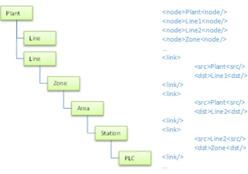
To provide the option to view the same set of objects in different ways, arranging them in different hierarchies or networks depending on the desired viewpoint the basic data structure is proposed to be based around nodes and links. An example of how a traditional hierarchy could be represented can be seen in Figure 1.
Once the objects are identified other tools, services or systems are intended to provide detailed information, based on the object identity provided by the Plant description. Other systems anticipated to provide such information are the systems managing configuration, services for orchestration, systems for meta-data and specialized engineering tools, but there are other possible services as well.
[image:3.595.313.559.50.222.2]The main benefit of the proposed solution is intended to be a lower risk for misunderstandings between different organizations and disciplines without the need to force all involved parties to implement one standard that works for all purposes. Possible additional benefits include a lower threshold for utilizing engineering and design data from different sources that may be organized according to different standards.
Fig. 1. Hierarchy described by a nodes-and-links data structure
II. EXISTING STANDARDS AND RELATED WORK
A number of interesting standards for exchange of en-gineering data have been identified and discussed. However, there is no clear solution for the purpose of providing a basis for interaction between engineering tools of the wide spectrum of domains and disciplines covered by the Arrowhead project, including but not limited to production facilities, building au-tomation, infrastructure, electric vehicles and energy systems.
The Reference Architecture Model Industrie 4.0 (RAMI4.0) status report [4], a product of the German initiative Industrie 4.0, is centered around the standards IEC 62890 for structuring the Life Cycle and Value Stream, combined with the two standards IEC 62264 (ISA-95) and IEC 61512 (ISA-88) for structuring the hierarchical levels. At a more detailed level the report suggests a number of standards for different aspects. For implementation of the Communication layer the report suggests OPC-UA, for the Information layer IEC 61360 (ISO 13584-42), eCl@ss, Electronic Device Description (EDD) and Field Device Tool (FDT) are suggested. Field Device Integration (FDI) is suggested as integration technology and for end-to-end engineering the report suggests ProStep iViP, eCl@ss and AutomationML (which uses a topology based on IEC 62424).
OPC-UA (IEC 62541) [12] is the data exchange standard for platform and vendor independent communication across vertical and horizontal layers within industry in a client-server environment. OPC UA defines generic services and in doing so follows the design paradigm of service-oriented architecture (SOA). In contrast to classic Web services, a number of generic services are already defined and standardized and thus WSDL is not required. Services are organized into logical groupings called service sets. Service requests and response are communicated through message exchange (either using binary protocol on TCP/IP or as a web service) between client and server.
representation and exchange; ISO 15531 for Industrial man-ufacturing management data. The same technical committee has also released a draft for ISO 18828 that will standardize Manufacturing process and management information.
The ISO 15926 standard does allow for multiple disciplines and provides strong support for management of types, classes and instances of objects throughout the complete life-cycle of a process plant. However the ISO 15926 standard is very extensive, as Holm et al. [14] illustrate in the comparison between IEC 62424 and ISO 15926, through the representation of a belt conveyor according to both structures.
The IEC 62264 (ISA-95) is a commonly used standard that defines the hierarchical structure of interaction between an in-dustrial control system and enterprise systems, specifically the functional data flow and object models. However the standard does not in great detail specify the engineering data of the control systems and does not go into the interaction between engineering data of the control system and engineering data of electrical, mechanical or other systems that the control system by necessity are related to.
The ISO/IEC/IEEE standard 15288:2008 [15] specifies a number of concepts that can be useful in the engineering of a large system, while not going into the details of each domain. This standard contains many useful concepts but is not yet widely adopted by the industry and still requires further details for fruitful interoperability between engineering tools of different disciplines.
The standard IEC 81346 describing Industrial systems structuring principles is common for identifying systems and objects in electrical installations within European industries, and is to some extent used within automation systems in such facilities for naming and structuring objects connected to the automation systems. In a similar manner IEC 61850 is used in electrical substation automation systems. The IEC 61850 data model has been mapped to standardized protocol DNP3 (Distributed Network Protocol) [16] for interaction with other automation systems and some interoperability with IEC 61499 has been shown by Yang et al. [17].
The work by Chen and Lin [18] on a Digital Equipment Identifier (DEI) system, which intends to uniquely identify manufacturing equipment and organize data retrieved from vendor Web sites or databases, could be seen as a potential further standard that is used to describe systems at an auto-mated production site.
As can be seen there are a great number of different standards that in some way concern the modularity of a large production system, by dividing it into objects, functions, locations or systems. To a large extent the modules are likely to be comparable, representing the same physical component, but there may be cases where certain components are neglected as modules for one discipline while very important for another.
III. ENGINEERING TOOL INTEROPERABILITY
[image:4.595.312.560.54.196.2]As with the interoperability of the kind of systems that are the main target of Arrowhead as a whole, the interoperability of engineering tools is possible today as long as all partners follow the same standard or use the same suite of tools from one system provider [19]. However, as the Arrowhead project
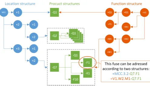
Fig. 2. In IEC81346 the three aspects Function, Location and Product are commonly used to describe different viewpoints of industrial systems
targets widely different domains [20], including different kinds of production facilities, building automation, infrastructure, mobile system such as electric vehicles and energy systems; and the engineering tools of those domains have to cover different aspects and life-cycle phases, there are many stan-dards that could be used depending on the domains and life-cycle phase. A first stage of enabling broader interoperability between engineering tools will be to identify a basic form of interaction using services between different tools.
As many domains already follow standards relating to one or more of the aspects that this task aims to address it seems unreasonable to make all of them follow one standard. Instead some inspiration can be taken from the discussions that have already been had within Arrowhead regarding communication protocol translation[21], where the efforts have been concen-trated on a solution using one protocol as an intermediary layer and focus on translating to and from this one protocol rather than direct translation between all protocols. Many of the standards concern the parametrization of the object data, which is important for compatibility between tools within one domain, but as the target here is interoperability between tools from different domains it may be sufficient to focus on a few key parameters for each object and the different relations the objects have between themselves.
A. As a service in the Arrowhead Framework
The purpose of the Plant Description service is to provide a basic common understanding of the layout of a plant or site, providing possibilities for actors with different interests and viewpoints to access their view of the same data set provided by other sources. An source of inspiration for the design was the standard ISO/IEC 81346 which specifies that for studying objects and their relations it may be useful to look at them from different viewpoints, highlighting different aspects of the objects and relations. This standard is focused on the three aspects function, product and location, although the design is intended to be capable to address other viewpoints as well.
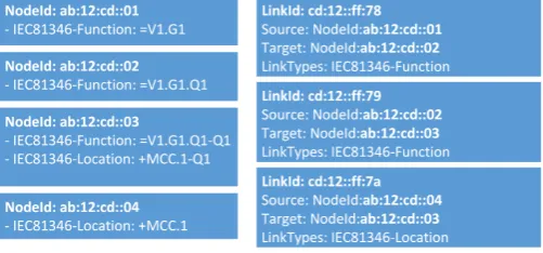
Fig. 3. An example of how the object -Q1 in Figure 2 and three connected nodes could be described by a data structure based on nodes and links.
B. Nodes and links
In an effort to keep the amount of data stored at a lower level the proposed solution will only store a very limited amount of data about each object within the Plant description system, instead relying on other data sources, such as existing databases and engineering tools, to provide more specific data according to the standards relevant in the specific domain and engineering discipline.
Therefore the data stored about each object is limited to (1) a unique identifier used within the Plant description system and (2) a list of data pairs containing one pair for each standard or other system in which the object is identified and its identifier within that standard and system. Each of these objects is considered a node. Similarly each relation between two objects will be stored as a link, containing four data items: (1) a unique identifier used within the Plant description system, (2) the identifier of the node that is the source of the link, (3) the identifier of the node that is the target of the link and (4) a list of standards and systems in which these two nodes are linked to each other.
Figure 3 illustrates how the nodes =G1, =Q1, -Q1 and +1, and their relations from Figure 2 can be described by a set of nodes and links.
IV. PLANT DESCRIPTION USE CASES
A. Design and commissioning
In a common scenario a group of engineers from different disciplines collaborate to design an automation System of Systems, based on commercially-of-the-shelf (COTS) available automation components, using different engineering tools and standards as appropriate to their respective disciplines. Main requirement is that all engineering tools use a modular ap-proach, identifying components as modules, objects, subsys-tems or similar, that can be combined into a larger automation system.
The engineers will, throughout the whole process, use the Plant description as a reference tool for objects and systems that have been identified and how they are related to each other. At the early stages the Plant description can help engineers from different disciplines to coordinate their work, even though the design, names of objects, and responsibilities of subsystems may not be fully decided yet.
As engineers from difference disciplines start to populate the design with specific objects, the data can be synchronized between design tools using the Plant description. Throughout the design phase, all of the engineering data is still stored and maintained in the formats preferred by the engineering tools in their respective databases. The data in the Plant description should be limited to what objects are present in the separate databases, how they are identified and what their relations are.
As the systems become ready for commissioning the plant description can allow technicians to navigate the design using the structure that best fits their knowledge and requirements, while still having the possibility of accessing engineering data from the respective disciplines. Once the systems are commissioned there can be made a direct link between the actual hardware and software on the device and the data from the design and engineering process.
The use of the Plant description should lower the risk of misunderstandings and help identify cases, primarily during design and engineering, where different disciplines use differ-ent names for the same object.
B. Automotive industry
In an effort to implement the concepts and vision of Industry 4.0, Ford Motor Company, UK is currently un-dergoing a development phase which purpose is to achieve integration of the increasing number of interconnected devices deployed in power train assembly plants. In addition to the PLC-based (Programmable Logic Controllers) devices used to control automated machines, several other types of industrial connected devices are being deployed on the production system itself or linked to various other assets in the shop floor; RFID tags/antennas systems are fitted on material transport and storage (i.e. pallets, racks) for tracking track material flow through the shop floor. Smart tooling and wearable sensors and trackers are used to monitor manual or semi-automatic operations (i.e. where human operations are required). The de-ployment of Resource and Energy Monitors allows collecting contextual data such as energy, temperature and vibration for critical assets in the shop floor. Most of the devices used are commercial off the shelf product (e.g. smart tooling, energy monitors) which deployment and operation rely on specific and often proprietary data structure, connectivity and DBMS (Data Base and Management Systems) back ends.
Fig. 4. Four different system hierarchies as used in the automotive industry
also be deployed only on a sub set of the entire production line so that sub part of the system might only be partially defined compared to others. Similar heterogeneity also exists across data models used to support specific functionalities; for instance the MAXIMO maintenance database used by Ford globally, relies on a data model aligned to maintenance specific constraints and strategies.
[image:6.595.314.558.56.217.2]Physical devices are uniquely identified, using IP addresses (if connected to a TCP/IP based network) or other form of identifications. For instance, brass plates and 2D tags are used to identify physical asset in the shop floor. The same assets or devices also exist as a uniquely identified entry in the Data Base used to store the information generated by or describing the asset. In this context, the semi-generic descriptive model provided by the Plant Description service has been used to a) capture the structure of various sub systems and network of de-vices that compose the complete production line and facilities and b) define the mapping between different assets and devices IDs using the Nodes and Links as described in section III-B. The plant description model and web services, and ID mapping approach were used to support the implementation of the so-called Fault Tracker application, developed by the WMG in University of Warwick. The Fault Tracker an application targeted at mobile devices deployed in the shop floor, and was designed to support machine preventative and fault-fixing maintenance operations of automation systems. Figure 5 shows a sequence of screens that illustrate the functionality of the Fault Tracker Application, and how the ID mapping informa-tion was used to aggregate data from different systems and data bases into a rich engineering view; a) Fault information and/or maintenance work orders are retrieved from either the system interfacing with the control network or the maintenance database system (MAXIMO in this case); b) Plant and shop floor layout data is retrieve and used to provide location and guidance to the faulty system; c) view of and information about faulty component is provided using data generated during the engineering or commissioning phases (e.g. electrical diagrams, 3D CAD, product build information, etc.) in order to assist diagnostic; c) the user can then upload updated maintenance information or upload fault fixing information back to the maintenance database and conduct additional action such as ordering parts or update maintenance schedule.
Fig. 5. Four different system hierarchies as used in the automotive industry
The Plant Description database holds the mapping infor-mation that links different ID types. In the scenario described above, the faulty assets would be logged again a MAXIMO-defined ID (Asset ID), which would then be used to retrieve the ID of the object in the plant layout database that holds the asset location in the shop floor (i.e. PICON number providing line/zone/area information). The ID mapping information is then used to retrieve various entries in other databases (i.e. PLM resource and process description, vendor documentation) which information is required to support and complete the maintenance or fault fixing operations. The Plant description service in this case, provides a key element in facilitating the logging of and the access to various data sets while avoiding rigid and integrated data models, which is essential in enabling the design of opened and scalable representation of Physical systems and their digital representation (system Cyber representation).
V. CONCLUSION
The initial purpose of the solution presented in this paper was to provide a simple service interface to navigate different aspects of the standard IEC 81346, most notably to be able to switch between the function aspect and the location aspect, without having to provide all of the detailed data included in each object.
The solution presented in this paper constitutes an al-ternative for the exchange of engineering data which does not force all systems to use the same standard or require full compatibility between all relevant standards. The solution provides a basic structure on top of which further compatibility between engineering standards can be developed.
ACKNOWLEDGMENT
The authors would like to thank all partners of the Arrow-head project for the fruitful discussions and the ARTEMIS JU and ECSEL JU for funding, within project Arrowhead, grant nr. 332987.
REFERENCES
[1] R. Yang, Process Plant Lifecycle Information
Man-agement. AuthorHouse, 2009. [Online]. Available:
https://books.google.se/books?id=zmgzdjf1GR0C
[2] B. P´atkai, L. Theodorou, D. McFarlane, and K. Schmidt, “Requirements for rfid-based sensor integration in landing gear monitoring–a case study,”Power, vol. 5, p. 4, 2007.
[3] J. H. Henning Kagermann, Wolfgang Wahlster, “Recommendations for implementing the strategic initiative INDUSTRIE 4.0,” acatech -National Academy of Science and Engineering, Tech. Rep., 2013. [4] P. Adolphs, H. Bedenbender, D. Dirzus, M. Ehlich, U. Epple,
M. Hankel, R. Heidel, M. Hoffmeister, H. Huhle, B. Krcher, H. Koziolek, R. Pichler, S. Pollmeier, A. Walter, B. Waser, and M. Wollschlaeger, “Status Report - Reference Architecture Model Industrie 4.0 (RAMI4.0),” VDI - Verein Deutscher Ingenieure e.V. and ZVEI - German Electrical and Electronic Manufacturers Association, Tech. Rep., July 2015. [Online]. Available: http://www.zvei.org/Downloads/Automation/5305 Publikation GMA Status Report ZVEI Reference Architecture Model.pdf
[5] ITEA and ARTEMIS-IA, “ITEA ARTEMIS-IA High-Level Vision 2030 - Opportunities for Europe,” ITEA and ARTEMIS-IA, Tech. Rep., 2013. [6] A. J. Braaksma, W. W. Klingenberg, and P. P. van Exel, “A review of the use of asset information standards for collaboration in the process industry,” Computers in Industry, vol. 62, no. 3, pp. 337 – 350, 2011. [Online]. Available: http://www.sciencedirect.com/science/article/pii/S0166361510001387 [7] V. Vyatkin, “Software engineering in industrial automation:
State-of-the-art review,”Industrial Informatics, IEEE Transactions on, vol. 9, no. 3, pp. 1234–1249, Aug 2013.
[8] C. Pang, V. Vyatkin, and W. Dai, “Iec 61499 based model-driven process control engineering,” in Emerging Technology and Factory
Automation (ETFA), 2014 IEEE, Sept 2014, pp. 1–8.
[9] F. Himmler, M. Gepp, J. Vollmar, T. Jager, and M. Amberg, “Function-based engineering framework for the standardization of industrial plants,” inIndustrial Electronics Society, IECON 2014 - 40th Annual
Conference of the IEEE, Oct 2014, pp. 4909–4915.
[10] M. Schleipen. (2014) Open standards for Industry 4.0 Tools and offer around AutomationML and OPC UA. [Online]. Available: http://www.iosb.fraunhofer.de/servlet/is/46944/AutomationML en.pdf [11] A. T. Johnston, “OpenO&M and ISO 15926
Col-laborative Deployment,” October 2009. [Online]. Avail-able: http://www.mimosa.org/presentations/openom-and-iso-15926-collaborative-deployment
[12] W. Mahnke, S.-H. Leitner, and M. Damm,OPC Unified Architecture. Springer, 2009.
[13] Y. Fukuda, “Standardization for manufacturing systems in iso,” in
ICCAS-SICE, 2009, Aug 2009, pp. 955–958.
[14] T. Holm, L. Christiansen, M. Goring, T. Jager, and A. Fay, “Iso 15926 vs. iec 62424 - comparison of plant structure modeling concepts,” in
Emerging Technologies Factory Automation (ETFA), 2012 IEEE 17th
Conference on, Sept 2012, pp. 1–8.
[15] ISO/IEC/IEEE International Standard - Systems and software
engineer-ing System life cycle processes, Std., Jan 2008.
[16] “Ieee approved draft standard for exchanging information between networks implementing iec 61850 and ieee std 1815(tm) (distributed network protocol - dnp3),”IEEE P1815.1/D8.00, September 2015, pp. 1–356, Jan 2015.
[17] C.-W. Yang, J. Xu, and V. Vyatkin, “Towards implementation of iec 61850 goose messaging in event-driven iec 61499 environment,” in
Emerging Technology and Factory Automation (ETFA), 2014 IEEE, Sept
2014, pp. 1–4.
[18] T. Chen and Y.-C. Lin, “A digital equipment identifier system,”Journal
of Intelligent Manufacturing, pp. 1–11, 2015. [Online]. Available:
http://dx.doi.org/10.1007/s10845-015-1071-3
[19] R. Harrison, D. Vera, and B. Ahmad, “Engineering methods and tools for cyber-physical automation systems,” 2016, Proceedings of the IEEE, Accepted October 2015 (In Press).
[20] F. Blomstedt, L. Ferreira, M. Klisics, C. Chrysoulas, I. Martinez de Soria, B. Morin, A. Zabasta, J. Eliasson, M. Johansson, and P. Varga, “The arrowhead approach for soa application development and doc-umentation,” in Industrial Electronics Society, IECON 2014 - 40th
Annual Conference of the IEEE, Oct 2014, pp. 2631–2637.