ISSN: 1816-949X
© Medwell Journals, 2020
Determining Length of Mining Front in Non-Blast Open Mining of
Complex Structure Carbonate Deposits
Sergey Igorevich Fomin, Vinogradov Ivan Petrovich and
Lapshin Nikolay Sergeevich
Saint Petersburg Mining University, Saint Petersburg, Russia
Abstract: Traditionally, during mining complex structure carbonate deposits, the bore-and-fire technique of rocks preparation for excavation and loading works, is used. With all its advantages, the bore-and-fire technique has several disadvantages. One of its major disadvantages is absence of opportunity to conduct selective mining. Layer-by-layer milling machines enable to conduct multi-lift mining, to improve the quality of produced minerals and to improve mining safety. Establishing the dependence of the length of the mining front in open mining of complex structure carbonate deposits, with use of layer-by-layer milling machines, on the specific operational costs, will enable, in practical terms, to increase the economic efficiency of mining. The holdings having production of cement as their ultimate goal, are complex systems integrated vertically and horizontally, include at the level of mineral resource base, not only carbonate deposits but also deposits of non-ore construction materials required for covering their own needs of sand and sandstone. Application of non-blast technology of developing carbonate deposits sets the same requirements to deposits of non-ore construction materials, which are located in the vicinity of such companies. Such non-ore construction materials include deposits of sand-gravel mixture. Application of up-to-date mobile crushing and screening equipment enables to obtain sand and crushed stone from gravel and boulders without resorting to blast works near the areas where sand and crushed stone are consumed. In addition, mobile crushing and screening equipment can also be used for obtaining crushed stone from limestone produced by means of layer-by-layer milling machines. Establishing the dependence of the length of the mining front in open mining of complex structure carbonate deposits, with use of layer-by-layer milling machines, on the specific operational costs, will enable to optimize the deposit mining system and to reduce, in practical terms, costs on exploration.
Key words:Autodumper, milling surface miner, mining front length, mobile structure, complex structure deposits, costs
INTRODUCTION
Cement industry is a highly concentrated industry. Most large cement production companies integrated into holdings. Both vertical and horizontal integration is common for such holdings. Horizontal and vertical integration is manifested at all the levels of such systems. Horizontal and vertical integration can be related to sales of carbonate rocks of several pits to the same plant, or to unification of plants on manufacturing the final product (cement) for selling under the same brand and so on.
Large holdings on cement production include not only pits on carbonate rocks production but also various pits on production on non-ore construction materials-crashed stone, sand, sand-gravel mixtures and others. As a rule, pits of non-ore construction materials are necessary in the structure of holdings for meeting their own needs in core construction materials-sand and crushed stone.
In construction, crushed stone and gravel of dense rocks for construction works “cube-shaped” crushed stone
is of the highest demand. Production of such crushed stone is, as a rule, related to drilling and blasting operations.
For many sandstone and gravel deposits, it is typical to organize works with partly or full processing of minerals in bottom-hole movable or semi-stationary units. Part of them produce ready-made products, including fractionated gravel and crushed stone.
According to expert assessments, for most construction facilities, presence of grains of plate and needle shape within 35% share is permissible (Butkevich et al., 2006; Louchnikov et al., 2014).
Movable crushing and screening plants can be applied in mining mineral deposits of any small scopes of reserves, moving from one deposit to another, being able to observe the main principles of constructing a flow chart: no excessive crushing or transporting.
Combination of various ways of mineral resources quality management and application of moveable equipment will enable to maximally reduce environmental
load on the nearby areas via. reducing the amount of operating equipment and engaging minimal areas in mining. Mining of deposits with application of mobile crushing and screening plants fits in the concept of vertically integrated holdings on cement production (Fomin, 2017).
Analysis of the operations of the companies developing carbonate deposits of cement minerals, indicated that the production of the mineral is conducted with application of bulk mining without screening when all blasted rock mass is transported to crushing and screening plant or selectively. Bulk mining ensures high mineral output of the pit but it is not effective in developing complex structure carbonate deposits (Fomin et al., 2007). In the mode of the mineral occurrence, practically all carbonate deposits are represented by seam-shaped or lenticular forms of deposits.
Separate mining of thin bed seams, related to application of special methods of blasting and bottom hole excavator sorting, is technologically difficult to implement and plausible in only easily distinguishable types of mineral, for this reason, it is not always possible to achieve the required quality of mineral.
The highest production of moveable units and milling surface miners is achieved with presence of a significant mining front, when continuous mining of the massif can be ensured with minimal number of auxiliary operations and idle passes.
Purpose of research: Complex structure deposits (Kosukhin et al., 2019; Sidorov et al., 2018; Sidorov and Ponomarenko, 2017) having several seams of mineral, should be mined layer-by-layer because such a technology enables to avoid contamination of mineral and to conduct its selective excavation. The degree of the quality of the mineral produced via milling surface miners, depends to a significant extent on the qualification of the surface miner operator and the correct choice of the type of cutters for a certain kind of mineral (Fomin, 2016).
Thin layer multi-lift mining of mineral, with application of milling Surface Miners, enables to conduct non-blast production of mineral. Establishing the dependence of the length of the mining front in open mining of complex structure carbonate deposits, with use of layer-by-layer milling machines, on the specific operational costs, will enable to optimize the deposit mining system and to reduce the operational costs of production of minerals.
MATERIALS AND METHODS
Methods of research: The main technological peculiar feature of the application of milling surface miners for open mining is the fact that the bench serves as bottom hole and the surface of horizontal or flat area where thin
layer multi-lift mining is executed. In this case, on the border of the working area (the border of the working block or at the final pit outline), stepped slopes are formed, their dimensions are set by the surface miner design and parameters.The fact that thin layer multi-lift mining cannot be performed by means of traditional mining equipment, currently causes the inclusion in the productive area of interstratified layers having significant thickness (0.5-3.0 m depending on mining conditions), interstratified layers of substandard quality or just stripped rocks.
The ability to mine the massif by thin layers (5-10 to 80 cm, depending on the surface miner dimension type) with accuracy up to ±1 cm with simultaneous loading rock mass having grain size by 85-90% up to 5 cm. through console unloading conveyor, enables not only to ensure flow of mining but also to improve the quality of the produced mineral via. reducing dilution by stripped rocks, to reduce the losses up to minimum and also to reduce crushing costs.
At the pits on production of limestone, marl and gypsum, in addition to solving the issues related to environment protection (refusal from drilling and blasting operations enabled to develop the areas of deposits, located near residential and industrial buildings and structures), costs of mining, transportationа and crushing are reduced. Simultaneously, the output increases by a factor of 2-2.5. In the process of performed work, it was established that the average time of loading an autodumper of 28 tons in load capacity is about 2 min.
Analysis of experience of using milling surface miners in limestone production demonstrated that the time spent on U-turn of the surface miner for milling in the reverse direction, changed from 6-12 min, amounting 9 min 20 sec on average. Time for replacement of the autodumper at the surface miner in the process of its execution of loading work, was about 30 sec on average. With decrease of the mining front from 200-100 m, the number of U-turns increased from one to five and the total time spent on surface miner U-turns, increased 6-50 min, which naturally affected its output (Pikhler, 2008; Pikhler, 2001; Pikhler, 2000; Raikov, 2002).
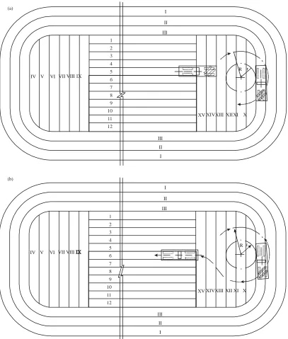
With a small length of mining front (100-150 m), shuttle car operation scheme is more preferable (Fig. 3.10), as the time for the surface miner turn at the end of operating pass is longer than the time of the reverse pass. In this case, coal cutter mine workings at the block end faces, are constructed in the process of flow mining (minimum 3 passes) and the other passes (from 4-14) are executed by shuttle car operating scheme. With the big length of the mining front, a scheme with U-turn and milling in reverse direction is expedients (Fig. 1).
1 2 3 4 5 6 7 8 9 10 11 12
R r I
II III
IV V VI VII VIII IX
XV XIVXIII XIIXI X
I II III (a)
1 2 3 4 5 6 7 8 9 10 11 12
R r I
II III
IV V VI VII VIII
XV XIVXIII XII XI X
I II III (b)
Fig. 1(a-b): Surface miner work scheme in developing the block with mining front length more than 150 m minimal radius of the turn. For this purpose, the first three
passes (minimally) are executed by the flow scheme. Then, excavating of mine workings is started, for this purpose, perpendicular to the long axis of the block, passes are executed from IV-IX and from X-XV by the shuttle scheme, after that, one by one, passes from 1-12 are executed by the scheme with U-turn and mining development from one side to another.
In so doing the operating cycle during mining of the layer includes:
C Surface miner entering from the coal cutter mine working to the lane
C Milling the lane
[image:3.612.105.512.94.573.2]C Turn in the opposite coal cutter mine working (Fig. 1)
The efficiency of the mining system operation, including a milling surface miner and other means of transport, to significant extent depend on the mining front length, changing with mining works development.
The optimal length of the mining front for the system, must ensure the specified output of mining enterprise, the minimal cost price of production.
Annual output of mining system:
QC = Uf Lf h, m 3
/year (1)
where, Uf is an annual advancing of the mining front, m.,
Lf is mining front length, m., h is bench height, m. In transporting mineral by pit autodumpers, the total specific operational costs on automobile transport, depending on the mining front length:
CA = CT.A.+CC.D.+CP.D., roubles/t (2)
where, CT.A. are the specific costs for transporting the mineral by autodumpers, roubles/t., CC.D. are the specific
costs for road construction, roubles/t., CP.D. are specific
costs for road maintenance, roubles/t.
The average distance of transporting mineral: (3)
f f
TP P.Z.
L U
L l , M
2
where, Lf is the mining front length, m, Uf is the annual advancement of the mining front, m, lP.Z. is the distance of
transporting from the point of unloading to the beginning of the milling surface miner entering, m.
Operational output of autodumper per shift:
(4)
a av CM
a
f f p.z.
G T
Q , t. / shift
L U 2l
where, Ga is the autodumper load capacity, t;avis the average speed of the autodumper, m hG1 T
CM is the
duration of automobile transport operation within a shift, hours.
The specific costs in transporting the mineral by pit autodumpers:
(5)
M.C. f f p.z.
T.A.
a av CM
A L U 2l
C , roubles / t
G T
where, CM.C. is the cost of a vehicle shift of an autodumper
in roubles per shift.
Specific costs of main road construction:
(6)
c.d.M c.d.M.
e
C' Uf
C , roubles / t
Q
where, C’c.d.M, are operational costs of constructing 1 m. of
the main road in roubles, Qe is the annual output of a milling surface miners, t.
Specific costs of main road maintenance:
(7)
p.M. f p.M
e
C' U
C , roubles / t 2 Q
where, C’p.M. are costs for maintenance of 1 m of main
road, in roubles.
Total specific costs in transporting mineral by automobiles, depending on the front length of production works:
d.M.
M.c. f f p.z. f ' '
a p.M.
a av CM e
C (L U 2l ) U
C (C 0,5 C ) roubles / t
G T Q
(8) (9) 1 e f f p Q
, m year
L h
where, γp is density of mineral, t/m 3.
With considerations of the Eq. 2-9:
(10)
м.с. f м.с. e
а
а av см а av см f р
м.с. р.z. d.м. p.м.
a av см f р
С L С Q
С
G Т G Т L h
2 С l C 0,5 С
, roubles / t
G Т L h
For finding the optimal value of the mining front length, it is necessary to take the first derivative of the equation (Eq. 10) and equate it to zero
The first derivative
d.м. p.м. a м.с. м.с. e
2 2
f a av см f a av см р f р
С 0,5 С
dC С С Q
dL G Т L G Т h L h
(11) The second derivative:
2 a 2 f dC 0 dL
hence, the dependence (Eq. 10) has the minimum. We equate the first derivative (Eq. 11) to zero and, solving the equation in regard of Lf, we find the optimal mining front length in transporting mineral by automobiles:
(12)
м.с. e а av см d.м. p.м.
f
м.с. р
С Q G Т (С 0,5 С ) L С h
RESULTS AND DISCUSSION
1600
1550
1500
1450
1400
1350
C
a (
ro
u
b
les
/t
)
0 100 200 300 400 500 600 700 800 Lf (m)
Fig. 2: Graph of the dependency of the overall specific costs from the mining front length of the milling surface miner operation, with transportation of mineral by automobiles
mined area length, a need of frequent hauls arises and also, preparatory work time increases in aligning the operating platform.
Figure 2 has the graph of the dependency of the overall specific costs from the mining front length of the surface miner operation, with transportation of mineral by automobiles.
The results of the calculations presented in Fig. 1, demonstrate that the optimal value of the mining front length of milling Surface Miner, with transportation of minerals by automobiles, will be 190-230 m.
With increase of the mining front length, the total specific costs reduce until the reach the optimal value and then gradually increase.
Analysis of the obtained dependency (Eq. 12) enabled to identify that with the increase of the mining front from 150-250 m, the operational performance of milling surface miners increases by 8-10%.
CONCLUSION
The length of the mining front of the milling surface miner in mining horizontal complex structure deposits depends on the following factors: Mineral output of the pit, Pace of mining front advancement, Total thickness of seams of minerals, Output of the moveable unit, Type of pit transport at mining. In designing a pit, it is necessary to determine economically expedient values of the excavation block length, the mining front for each means of transport, with consideration of the type of loading equipment and the flow charts applied in deposit mining. The optimal mining front length should be determined with consideration of having moveable units of the specified output, adopted mining technology and ensuring the economic effectiveness of deposit mining.
REFERENCES
Butkevich, G.R., 2006. Industry of non-ore construction materials: Contemporary state and peculiar features. Min. Ind. J., 6: 1-6.
Fomin, S.I., 2016. Justification of technological solutions in organizing mining of ore pits. Notes Min. Inst., 221: 644-650.
Fomin, S.I., 2017. Analysis of non-blast technology of multi-lift mining with application of milling surface miners in open mining of cement minerals deposits. Cem. Appl., 1: 42-44.
Fomin, S.I., D.V. Pasynkov and V.V. Ivanov, 2007. Analysis of the effects of the factors of mineral resources market on output of pits. Contemp. Issues Min. Sci., 172: 121-125.
Kosukhin, N.I., D.V. Sidorov, I.I. Beloglazov and V.Y. Timofeev, 2019. Assessment of stress-strain and shock bump hazard of rock mass in the zones of high-amplitude tectonic dislocations. Conf. Ser. Earth Environ. Sci., 224: 1-5.
Louchnikov, V.N., M.P. Sandy and V.A. Eremenko, 2014. Ground support liners for underground mines: Energy absorption capacities and costs. Eurasian Min., 1: 54-62.
Pikhler, М., 2000. Area of improvement and results of application of surface miners Wirtgen Surface Miner in pits and cross-sections worldwide. Min. Ind., 1: 1-42.
Pikhler, М., 2001. Technologies and schemes of mining in using surface miners 2100 and 2200 SM of Wirtgen gmbh. Min. Ind., 4: 51-53.
Pikhler, М., 2008. Surface miners wirtgen 2500 SM in pits of Lipetsk career administration of open joint-stock company Lipetskcement. Min. Ind., 4: 18-22.
Raikov, А.B., 2002. New pit surface miner Wirtgen 2200 SM in Guinea republic. Min. Ind., 1: 1-5. Sidorov, D. and T. Ponomarenko, 2017. The development
of a software suite for predicting rock bursts within the framework of a system for ensuring geodinamic safety of mining operations. Intl. Mult. Sci. Geo Surv. Geol. Min. Ecol. Manage., 17: 633-638.
[image:5.612.75.294.88.219.2]