1
Faculty of Electrical Engineering,
Mathematics & Computer Science
Secure biometric verification
in a malicious attacker
model setting
R.H.D. Scholten (Ruth)
M.Sc. Thesis
January 2020
Abstract
Acknowledgements
The past year was more or less devoted to writing my thesis. Like many theses, there were bumps on the road, but overall I enjoyed it. Now the end has come and it is time for a new journey.
First of all, I would like to thank my supervisors, Andreas Peter, Tom Kevenaar and Raymond Veldhuis, for guiding me through the master thesis project and giving me feedback on my work. Especially, I would like to thank Andreas for the helpful meetings that we had and for pointing me into new directions whenever I was stuck.
Secondly, this thesis does not only mean the end of my graduation project, but it also implies the end of my student time. During my study time I did not only learn a lot about computer science and cyber security, but I also learned a lot about myself and life in general. Therefore I would like to thank all the people I met during my time in Enschede, because I would not have become the person as I am now without you.
In particularly, I would like to thank my roommates. Thanks for being my extended family, or ”gezinsvervangend tehuis” as my mother would call it in Dutch and for all the fun movie nights. As a computer science student among many guys, I really enjoyed being able to talk so much about girl stuff and let the weird side in myself come out.
I would also like to thank my friends that I met in the bachelor and master period. I made some really good friends from whom I know we will still be friends in the far future. I am also really grateful for the international friendships that I made and learn about new cultures.
During my time as a student, I was a member of RSK Enschede, a christian student association. I am really thankful for the seven years that I spent among great people whom I could share my faith with, experience so many fun things with and for everything I learned.
Contents
1 Introduction 6
1.1 Problem Statement . . . 7
1.2 Research Questions . . . 7
1.3 Contribution . . . 8
1.4 Outline of Thesis . . . 8
2 Background 9 2.1 Definitions . . . 9
2.1.1 Cryptographic Notations . . . 9
2.1.2 Security . . . 10
2.1.3 Attacker Models . . . 10
2.1.3.1 Semi-Honest Attacker . . . 10
2.1.3.2 Malicious Attacker . . . 11
2.2 Cryptographic Primitives . . . 12
2.2.1 ElGamal Encryption System . . . 12
2.2.2 Homomorphic Encryption . . . 13
2.2.3 Elliptic Curve Cryptography . . . 14
2.2.3.1 EC-ElGamal . . . 15
2.3 Basic Cryptographic Protocols . . . 15
2.3.1 Commitment Schemes . . . 15
2.3.2 Zero-Knowledge Proof-of-Knowledge . . . 17
2.3.2.1 Σ-Protocol . . . 17
2.3.2.2 Non-Interactive Zero-Knowledge Proofs . . . 19
3 Related Work 20 3.1 BTP schemes in the semi-honest model . . . 20
3.2 Biometric protocols in the mal. model . . . 21
4 Semi-Honest Protocol 22 4.1 Template Structure . . . 22
4.2 Protocol . . . 22
4.2.1 Key Setup . . . 22
4.2.2 Enrollment Procedure . . . 23
4.2.3 Verification Procedure . . . 24
5 Semi-Honest Key Release Protocol 26 5.1 Protocol . . . 26
5.1.1 Requirements . . . 26
5.1.2 Key Setup . . . 26
5.1.3 Enrollment Procedure . . . 26
5.1.4 Verification Procedure . . . 27
5.1.5 Proof of Security, Correctness and Requirements . . . 28
CONTENTS CONTENTS
6 Part. Mal. Key Release Protocol 30
6.1 Building Blocks . . . 30
6.1.1 GMW Compiler . . . 30
6.1.1.1 Preliminary Functionalities . . . 30
6.1.1.2 Protocol . . . 32
6.1.2 Equality of Exponents Proof . . . 34
6.1.3 Schnorr Signature Scheme . . . 35
6.1.4 Permutation Proof . . . 35
6.2 Protocol . . . 37
6.2.1 Key Setup . . . 37
6.2.2 Enrollment and Verification Procedure . . . 37
6.2.3 Proof of Security . . . 42
6.3 Design Choices . . . 42
7 Semi-Honest One-Round Protocol 43 7.1 Protocol . . . 43
7.1.1 Key Setup . . . 43
7.1.2 Enrollment Procedure . . . 44
7.1.3 Verification Procedure . . . 44
8 Performance Evaluation 46 8.1 Overview of Parameters, Scheme Instantiations and Protocol Components . . . 46
8.2 Computational Complexity . . . 47
8.2.1 Building Blocks . . . 48
8.2.2 Protocol Components . . . 48
8.3 Communication Complexity . . . 50
8.4 Experimental Analysis . . . 51
8.4.1 System Setup . . . 52
8.4.2 Results . . . 52
8.5 Discussion of Results . . . 56
9 Conclusion 57 9.1 Limitations and Future Work . . . 57
A Cor. Proof of S.H. Key Release Protocol 63 A.1 Sensor . . . 63
A.2 Server . . . 65
B Sec. Proof of S.H. Key Release Protocol 66 B.1 Case (a) . . . 66
B.2 Case (b) . . . 67
C Req. Proof for S.H. Key Release Protocol 68 C.1 Req. 1 . . . 68
C.2 Req. 2 . . . 68
D Cor. Proof of Part. Mal. Key Release Protocol 70 D.1 Sensor . . . 70
D.2 Server . . . 73
E Sec. Proof of Part. Mal. Key Release Protocol 74 E.1 Case (a) . . . 74
E.2 Case (b) . . . 75
E.3 Case (c) . . . 75
F Runtime Experiments 80
Chapter 1
Introduction
Biometric recognition is a means to measure physical characteristics (e.g. fingerprint, iris, voice, face, etc) of a person for identification or authentication purposes. Many of those characteristics are (highly) unique for each person and can thus be used as a distinctive measure to identify or authenticate a person. Physical characteristics are captured by a sensor device and stored in a digital format, called a probe. Subsequently the probe is compared to an existing biometric sample from a database by a verification server, which computes. Alternative identification or authentication methods are based on knowledge (e.g. password) or tokens (e.g. passport). These methods possess risks that biometrics do not have, such as the risk of forgetting or losing. In addition, passwords are often weak and can relatively easily be forged. Hence, biometrics is being used more and more in the field of identification and authentication [39, 56].
However, a major drawback of biometrics is the constant reuse of the same biometric in multiple authentication systems, as opposed to traditional authentication methods where multiple passwords and/or tokens are used. When a system is compromised, the biometric can never safely be used anymore in any authentication system ever again [54]. Hence, biometric templates are vulnerable to privacy problems such as identity theft [32]. The European Union has stated in General Data Protection Regulation 2016/679 [23] that biometric data is sensitive and must therefore be protected. Protection of biometric data is handled using so-called Biometric Template Protection (BTP) schemes in which secure templates are generated from biometric samples using a variety of methods, such as encryption [32]. According to the ISO/IEC IS 24745 standard [37], a secure template should possess the following two main properties:
• Irreversibility or non-invertibility: It should be computationally hard to retrieve the original biometric sample from the secure template [31, 49].
• Unlinkability: It should be computationally hard to detect whether two secure templates T1
andT2(T16=T2), have been generated from the same biometric sample [31, 49].
Two other important properties of a secure template are:
• Revocability, diversity or renewability: It should be possible to revoke a secure template T1
when it is compromised and generate a new secure templateT2from the same biometric sample
[38, 49, 56].
• Accuracyorperformance: The accuracy or recognition performance of a biometric authentication system should not be affected by the protection of the template. In other words, the trade-off between the False Acceptance Rate (FAR) and the False Rejection Rate (FRR) should remain reasonable [38, 49, 56]. The FAR denotes the ratio of illegitimate probes falsely accepted to the system compared to the total number of verification attempts. Equivalently, the FRR denotes the ratio of legitimate probes falsely declined to the system compared to the total number of verification attempts [47].
CHAPTER 1. INTRODUCTION 1.1. PROBLEM STATEMENT
1.1
Problem Statement
The BTP schemes as mentioned in the previous section are only secure against semi-honest attackers, rather than malicious attackers. In the former attacker model, a party compromised by such an attacker will not deviate from a predefined protocol, but may rather collect information, as opposed to the latter attacker model, in which an attacker performs malicious activity by not adhering to the protocol. More details on attacker models will be given in Section 2.1.3.
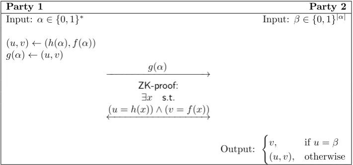
In this work, we will adjust the approach to secure and efficient biometric template protection as proposed by Peeters et al. [56] in such a way that it is secure in a one-sided malicious attacker setting. We chose the work of Peeters et al. [56], since the approach meets the secure template requirements as mentioned before and is based on a log-likelihood ratio classifier and elliptic curve ElGamal, which are considered state-of-the-art in terms of accuracy and efficiency, respectively.
Full malicious security will be achieved by having both parties prove their steps correctly to the other party who plays the role of a verifier. In other words, both parties will be enforced to behave in a honest manner. Unfortunately, we cannot protect biometric cryptosystems against the situation where both the sensor device and server are compromised by a (different) malicious attacker, for the obvious reason that if both parties deviate from the protocol, the proofs and verifications will be lost. For the approach by Peeters et al. [56] in the malicious model, we therefore make a case distinction:
(a) the sensor device is compromised by a malicious attacker and the server is either honest or compromised by a semi-honest attacker
(b) the sensor device is either honest or compromised by a semi-honest attacker and the server is compromised by a malicious attacker
Protecting biometric cryptosystems against both cases yields full malicious security. However, in this work, we will protect the protocol of Peeters et al. [56] only against case b, since in practice, the sensor device used in this context contains a non-tamperable capturing functionality and is thus better protected than the server. Enforcing the server to behave honest will yield a higher level of overall security in the biometric system.
Additionally, in the system of Peeters et al. [56] a simple ”yes” or ”no” answer is released upon comparison of a biometric probe with a database template. So called biometric-based key release systems exist that release a key when a comparison is successful. This key can for instance be used as a decryption key for sensitive data [64]. In this way there is no need to remember a decryption key and hence no risk of forgetting or weak password choices. Hence, in the current work, we will investigate and implement a way to release an key upon successful comparison of a biometric probe with a database template.
Currently, in the work of Peeters et al. [56], comparison of a biometric probe with a database template is jointly performed by the sensor device and the verification server. Although we mentioned earlier that in practice, usually, the sensor is better protected than the server, there are also cases in which there is no clear supervision on the secure setup of sensor devices. In these cases the only way to provide a better level of security is to protect the server against malicious attackers and have it do as many of the computations in the protocol as possible.
1.2
Research Questions
From the problem statement, we have deducted the following research questions. First of all, we will adapt the semi-honest protocol by Peeters et al. [56] such that it releases a key upon successful comparison, hence the following research question:
RQ1 How can we adapt the approach by Peeters et al. [56] in such a way that a key is released upon successful recognition instead of a simple ”yes” or ”no”?
From here on, we refer to the protocol as constructed in RQ1 as the semi-honest key release protocol.
Secondly, we make the semi-honest key release protocol secure against a malicious verification server. Hence, we will answer the following research question, which is the main focus of this work:
1.3. CONTRIBUTION CHAPTER 1. INTRODUCTION
From here on, we refer to the protocol as constructed in RQ2 as thepartially malicious key release protocol.
Subsequently, we will dive deeper into adjusting the semi-honest key release protocol such that the comparison is not a joint effort from the sensor and server anymore, but a black box from the sensor’s point of view and completely performed by the server. Accordingly, we will answer the following research question:
RQ3 How can we transform the semi-honest key release protocol in such a way that it is a one-round protocol in which comparison is done on the server side?
From here on, we will refer to the protocol as constructed in RQ3 as thesemi-honest one-round protocol.
Finally, we will assess the performance of the partially malicious key release protocol in terms of the number of operations and runtime and compare the performance to the work of Peeters et al. [56] and the semi-honest key release protocol as constructed in this research. To measure the runtime, we will create proof of concepts for both the semi-honest key release protocol and the partially malicious key release protocol. Hence, we will answer the following research question:
RQ4 How efficient is the partially malicious key release protocol and how does the partially malicious key release protocol compare to related semi-honest and malicious BTP schemes in terms of efficiency?
1.3
Contribution
To give a summary of the contributions in this work, we present the following three protocols:
• The semi-honest key release protocol, which uses the biometric recognition protocol by Peeters et al. [56] as a basis and binds a key to a biometric template which is released upon successful comparison. The key is independent from the biometric template and can be revoked. The semi-honest key release protocol is based on the NIST K-233 elliptic curve and uses ElGamal for efficiency purposes. The semi-honest key release protocol can process 443 biometric template comparisons per second, compared to 250 comparisons per second in the work of Peeters et al. [56], which is considered practical in realistic settings.
• The partially malicious key release protocol, which builds upon the semi-honest key release protocol and enforces a maliciously compromised server to behave in an semi-honest fashion, us-ing commitment schemes and zero-knowledge proofs. Moreover, we haven chosen the protection mechanisms in such a way that extending the work to the full malicious model is rather straight-forward. The partially malicious key release protocol is less practical than the semi-honest key release protocol, i.e. 25 comparisons per second can be done and therefore only practical if the accuracy is less important.
• The semi-honest one-round protocol, in which the sensor device sends its identity claim and probe vector to the server, and the server performs a comparison and sends the result back to the sensor device. We only give a theoretic overview of the protocol, therefore we consider the semi-honest one-round protocol as a stepping stone for further research in the area of one-round protocols.
1.4
Outline of Thesis
Chapter 2
Background
In this chapter, we will elaborate on the preliminary knowledge needed to understand the subsequent chapters. First, in Section 2.1 we present the most important definitions used in this work. Then, in Section 2.2, we describe some important cryptographic primitives. Finally, in Section 2.3, we explain the cryptographic protocols which form the basis for the upcoming protocols in this work.
2.1
Definitions
In order to understand the notation used in this work, we first briefly present some cryptographic notations in Section 2.1.1. Then, in Sections 2.1.2 and 2.1.3, we give formal and informal definitions of security and the two most essential attacker models used in secure multi-party cryptography.
2.1.1
Cryptographic Notations
In this work, we use the following cryptographic notations:
Notation Description
pkshared shared public key between server and sensor obtained by threshold encryption
pkss public key of sensor device
pksv public key of server
skss secret key of sensor device
sksv secret key of server
E(m) encryption function on messagemunder public keypkshared
Epk(m) encryption function on messagemunder some public keypk D1(c) decryption of ciphertextcunder sksv
D2(c) decryption of ciphertextcunder skss
AESK(c) AES encryption on ciphertextc using keyK
AES-DK(c) AES decryption of ciphertextcunder keyK [m]pk encryption of messagem under some public keypk [m] encryption of messagem under public keypkss
[[m]pk1]pk2 double-encryption of messagem, first under public keypk1 and then under public keypk2 [[m]] double-encryption of messagemunder public keypkshared
Com(m, r) commitment over messagemusing randomnessr
Com(m) commitment over messagemusing some uniformly distributed randomness
Decom(m) decommitment or reveal of messagem
PK(m) zero-knowledge proof-of-knowledge on inputm
BCT() execution of Basic Coin-Tossing protocol
AC() execution of Authenticated Computation protocol
ACT() execution of Augmented Coin-Tossing protocol c
≡ computational indistinguishability
2.1. DEFINITIONS CHAPTER 2. BACKGROUND
2.1.2
Security
Security in a multi-party computation setting can be defined by using the real/ideal paradigm. In-formally, in the ideal model, for a two-party computation setting, two parties send their inputs (x, y) to a trusted party who computes resultf(x, y) = (f1(x, y), f2(x, y)) and answers party 1 and 2 with
f1(x, y) and f2(x, y), respectively [28]. In the real model, parties jointly run a protocol without a
trusted party. Now the notion of security can be informally defined as follows [46]:
Definition 1. LetAbe an attacker in the real model andS an attacker in the ideal model.
A protocol π computes a function f in a secure way if ∀A → ∃S, such that any result of an execution of πwithA in the real model is computationally indistinguishable from an execution ofπ withS in the ideal model.
2.1.3
Attacker Models
In this work, we distinguish between two types of attackers or adversaries: semi-honest attackers and
malicious attackers [30]. We assume that if a party acts according to a certain adversarial model, it is compromised by an attacker of such kind.
2.1.3.1 Semi-Honest Attacker
A semi-honest attacker, also called honest-but-curious or passive attacker is an attacker who compro-mises a system and collects data as the system runs its protocol. The semi-honest attacker is passive in the sense that it does not intervene the system’s protocol run, i.e. the system continues to follow its protocol correctly. We assume that a semi-honest attacker is static, i.e. its attacker model does not change throughout the course of the protocol run [28].
Formally, we can define security in the semi-honest model for a general function as follows [28, 45]:
Definition 2. A function f securely computes protocol π in the semi-honest model if there exist probabilistic polynomial-time algorithms,S1andS2, such that:
{(S1(1n, x, f1(x, y)), f(x, y))}x,y,n c
≡ {(VIEWπ1(x, y, n),OUTPUTπ(x, y, n))}x,y,n (2.1)
{(S2(1n, y, f2(x, y)), f(x, y))}x,y,n c
≡ {(VIEWπ2(x, y, n),OUTPUTπ(x, y, n))}x,y,n (2.2) for secret inputs x, y∈ {0,1}∗,|x|=|y|, security parametern∈
Nand function outputsf1(x, y) and
f2(x, y). VIEWπi(x, y, n) and OUTPUT π
i(x, y, n) denote the view and output of party i ∈ {1,2} on protocolπ, respectively. Relation operator≡c indicates computational indistinguishability [45].
In other words, there exists an algorithm or simulatorSifori∈ {1,2}in the ideal model execution of πthat is, given the input and the output of Si and the general function output, computationally indistinguishable from the view of Party i and the protocol output in the real model execution of π[45].
In case functionalityf is deterministic, we can adopt a more apparent notion of security in the semi-honest model [28, 45]:
Definition 3. A deterministic function f securely computes protocolπ in the semi-honest model if there exist probabilistic polynomial-time algorithms,S1 andS2, such that:
{S1(1n, x, f1(x, y))}x,y∈{0,1}∗;n∈N c
≡ {VIEWπ1(x, y, n)}x,y∈{0,1}∗;n∈N (2.3)
{S2(1n, y, f2(x, y))}x,y∈{0,1}∗;n∈N c
≡ {VIEWπ2(x, y, n)}x,y∈{0,1}∗;n∈N (2.4) In other words, there exists an algorithm or simulatorSifori∈ {1,2}in the ideal model execution ofπthat, given the input and the output ofSi, is computationally indistinguishable from the view of Party iin the real model execution ofπ[45].
However, Definition 3 cannot be used in the context of probabilistic functions, since for a function that has randomized output it does not always apply thatOUTPUTπ(x, y, n) =f(x, y) for each set of input values (x, y) [28]. Therefore, we need to include the simulator’s output and the output of the protocol in Definition 2.
CHAPTER 2. BACKGROUND 2.1. DEFINITIONS
Formally, we can define correctness of a functionf as follows [45]:
Pr[OUTPUTπ(x, y, n)6=f(x, y)]≤µ(n) (2.5)
for a negligible functionµ(n).
Now, if a protocol computing a deterministic function conforms to the correctness condition, it inevitably means thatOUTPUTπ(x, y, n)≡c f(x, y) and thus [45]:
{(VIEWπ1(x, y, n), f(x, y))}x,y∈{0,1}∗;n∈
N
c
≡ {(VIEWπ1(x, y, n),OUTPUTπ(x, y, n))}x,y∈{0,1}∗;n∈
N (2.6)
Moreover, a simulator can compute functionality f(x, y), since he is given x and y. Therefore Equation 2.3 implies [45]:
{(S1(1n, x, f1(x, y)), f(x, y))}x,y∈{0,1}∗;n∈N c
≡ {(VIEWπ1(x, y, n), f(x, y))}x,y∈{0,1}∗;n∈N (2.7) Equations 2.6 and 2.7 together yield:
{(S1(1n, x, f1(x, y)), f(x, y))}x,y∈{0,1}∗;n∈
N
c
≡ {(VIEWπ1(x, y, n),OUTPUTπ(x, y, n))}x,y∈{0,1}∗;n∈
N
(2.8) and thus Definition 3 implies Definition 2 for a deterministic function. For more information, we refer to the tutorial on the simulation proof technique by Lindell [45].
2.1.3.2 Malicious Attacker
A malicious attacker, also called an active attacker, is an attacker who compromises a system and takes control of its protocol run for malicious purposes. The malicious attacker may corrupt data or abort the protocol for instance, i.e. a compromised system may deviate from its instructed protocol. In this work, we make the following assumptions about malicious attackers [28, 30]:
• Attacker modes are dynamic, i.e. any party can become a malicious attacker during a protocol run.
• Since our approach is a two-party protocol, we assume no collusion will take place. In case the server and sensor are both compromised by a malicious attacker, there is not much we can do. Therefore we assume either of the two parties is allowed to be malicious and the other should remain honest or semi-honest throughout the protocol run.
• If a (semi-)honest party detects malicious behavior from another party, it will abort the protocol.
A malicious attacker can engage in the following (malicious) activity [28]:
• A malicious party may participate in the protocol with input x0 ∈ {0,1}|x|, where x is the original input given to the party andx0 6=xapplies.
• A malicious party might abort the protocol at any time, even when the protocol has not finished. This means that a malicious party can abort when he receives the output of the protocol, even before the other (honest) party receives the output. Thus, two parties obtaining the result of a computation protocol synchronously (perfect fairness) is not possible in a two-party computation protocol. A malicious party can also abort even before the protocol starts.
We can define malicious attackers in the ideal model as follows [28]:
Definition 4. Let functionality f be defined as follows: f : 0,1∗× {0,1}∗ → {0,1}∗ × {0,1}∗, where f1(x, y) and f2(x, y) represent outputs of f for the first and the second party, respectively.
Furthermore, let B = (B1, B2) be a pair of probabilistic polynomial-time algorithms representing
strategies in the ideal model. B is admissible in the ideal malicious model if Bi(u, z, r) = u and Bi(u, z, r, v) =v for ∀u, z, r, v where there is at least one honest party i ∈ {1,2} and |Bi(u, z, r)|=
2.2. CRYPTOGRAPHIC PRIMITIVES CHAPTER 2. BACKGROUND
If Party 1 is honest, then:
Υ(x, y, z, r) = (f1(x, y0), B2(y, z, r, f2(x, y0))), wherey0 =B2(y, z, r) (2.9)
If Party 2 is honest, then:
Υ(x, y, z, r) =
(
(B1(x, z, r, f1(x0, y),⊥),⊥) ifB1(x, z, r, f1(x0, y)) =⊥
(B1(x, z, r, f1(x0, y)), f2(x0, y)) otherwise
(2.10)
wherex0 =B
1(x, z, r).
Equation 2.10 refers to the case where Party 1 enters the protocol by calling the trusted party with input B1(x, z, r). Since Party 1 may be malicious, its input might be substituted. In case
B1(x, z, r, f1(x0, y)) =⊥, Party 1 aborts the protocol after he received his output f1(B1(x, z, r), y),
before Party 2 receives his output from the trusted party. Otherwise, Party 1 does not abort the protocol and thus Party 2 receives his outputf2(B1(x, z, r), y) from the trusted party. In the case of
Equation 2.9, Party 2 may be malicious, but Party 1 obtains his output first from the trusted party, and thus there is no way for Party 2 to prevent the trusted party from answering Party 1.
We can define malicious attackers in the real model as follows [28]:
Definition 5. Letf be defined as in Definition 4 and letπbe two-party protocol to computef. Now, letA= (A1, A2) be a pair of probabilistic polynomial-time algorithms representing strategies in the
real model. Ais admissible in the real malicious model, if at least oneAicorrespond with the strategy as determined by π, which means thatAi ignores auxiliary inputz. The joint execution ofπ under A in the real model with input pair (x, y) and auxiliary inputz can be denoted asREALπ,A(z)(x,y) which defines the output pair which emerges from the interaction betweenA1(x, z) andA2(y, z).
Now we can define security in the malicious model as follows [28]:
Definition 6. A deterministic function f securely computes protocol π in the malicious model if for each pair of probabilistic polynomial-time algorithms A = (A1, A2) that are admissible for the
real model, there exists a pair of probabilistic polynomial-time algorithms B = (B1, B2) that are
admissible for the ideal model, such that:
{IDEALf,B(z)(x, y)}x,y,z c
≡ {REALπ,A(z)(x, y)}x,y,z (2.11) where x, y, z∈ {0,1}∗such that |x|=|y|and |z|=poly(|x|).
In other words, the emulation of a secure protocolπin the real model is computationally indistin-guishable from the computation of functionalityf in the ideal model.
2.2
Cryptographic Primitives
In this section, we present the type of encryption we use in this work: the ElGamal encryption system (Section 2.2.1), homomorphic encryption (Section 2.2.2) and elliptic curve cryptography (Section 2.2.3).
2.2.1
ElGamal Encryption System
The ElGamal encryption system is based on the discrete logarithm problem, which means that given a cyclic groupG with generatorg, it is computationally hard to retrievexforgx.
Given cyclic group G ⊆ Z∗p with generator hgi = G, order q = |G|, such that p, q ∈ P, q|p−1, secret key a∈R Zq and public keyh=ga modp, the encryption function on a messagem∈ G can be defined as follows [56, 62]):
c= (c1, c2) = (gr, m·hr) (2.12)
where r∈RZq.
For each encryption of messagem, the resulting ciphertext is different, due to randomnessr, hence why ElGamal is probabilistic. Moreover, ElGamal is secure under a chosen plaintext attack, meaning that, given the ciphertext, it is computationally hard for an attacker to recover the plaintext, assuming the Diffie-Hellman problem is hard [62].
CHAPTER 2. BACKGROUND 2.2. CRYPTOGRAPHIC PRIMITIVES
c2
ca
1
=m·h r (gr)a =
m·(ga)r (gr)a =
m·gar
gar =m (2.13)
Similar to the work of Peeters et al. [56], we chose to encode a messagemas exponent of generator gto support additions of similarity scores. See Section 2.2.2 for further explanation.
2.2.2
Homomorphic Encryption
Homomorphic encryption schemes are encryption schemes that allow computations in the encrypted domain such as addition and multiplication to be performed on ciphertexts.
Homomorphic encryption schemes can support multiplicative, additive or both operations in the encrypted domain. In case a homomorphic encryption scheme supports multiplicative operations, the following operation can be performed. Assume that we have two messagesm1 andm2, then:
[m1]·[m2] = [m1·m2] (2.14)
ElGamal is multiplicatively homomorphic as can be shown as follows. Assume that we have two ElGamal encryptions c = (c1, c2) and c0 = (c01, c02) generated from the same group under the same
public key. Then the following applies:
c·c0= (gr, m·hr)(gr0, m0·hr0) = (grgr0,(m·hr)(m0·hr0)) = (gr+r0,(m·m0)hr+r0) = (c1·c01, c2·c02)
(2.15)
If a homomorphic encryption scheme supports additive operations, then the following operation can be performed:
[m1]∗[m2] = [m1+m2] (2.16)
where∗denotes an arithmetic operation, such as multiplication or addition.
ElGamal is also additively homomorphic if we encode a message mas gm, as discussed earlier in Section 2.2.1. Recall that we are not able to retrievemif we only havegm, due to the discrete logarithm problem [56]. Now we can add two encrypted messages as follows, which we call homomorphic addition:
[gm1]·[gm2] = [gm1+m2] (2.17) An example for ElGamal encryptionscandc0:
c·c0= (gr, gmhr)(gr0, gm0hr0) = (grgr0,(gmhr)(gm0hr0)) = (gr+r0, gm+m0hr+r0)
(2.18)
In case we need to multiply a messagem, which has been encrypted, by a specific factorkin the context of additively homomorphic ElGamal, we perform a scalar multiplication as follows:
[gm]k = [gm·k] (2.19)
An example for ElGamal encryptioncand factork:
2.2. CRYPTOGRAPHIC PRIMITIVES CHAPTER 2. BACKGROUND
2.2.3
Elliptic Curve Cryptography
Many public key cryptosystems, such as ElGamal, are based on elliptic curves over finite fields, hence we call this approach elliptic curve cryptography (ECC). In this section, we will cover the basics of ECC, i.e. the operations on an elliptic curve, since we will express the computational complexity of the protocols in this work in the number of elliptic curve multiplications.
ECC provides the same security as cryptosystems which are directly based on cyclic groups, how-ever its finite field can be chosen smaller, since it is assumed that the discrete logarithm problem is harder to solve for elliptic curves than for prime integers. As a result, the performance in terms of implementation runtime is better for ECC [21, 42].
Elliptic curves can be defined as follows. In case the elliptic curve is based on Galois fieldFpwhere p is a sufficiently large prime, we can define its solution set in the form of a simplified Weierstrass equation as follows [21]:
E(Fp) :y2=x3+ax+b (mod p) (2.21)
where a, b∈Fp and 4a3+ 27b36= 0.
In case the elliptic curve is based on a binary fieldF2n, we can define the corresponding simplified
Weierstrass equation as follows [21]:
E(F2n) :y2+xy=x3+ax2+b (2.22)
where a, b∈F2n forn∈Pandb6= 0.
A special variant of an elliptic curve over a binary field is the Koblitz curve, wherea={0,1}and b= 1. The parameters of Koblitz curves have been chosen such that operations on the elliptic curve can be done more efficiently than standard curves over a prime or other binary fields [41]. In this work, we will make use of a Koblitz curve.
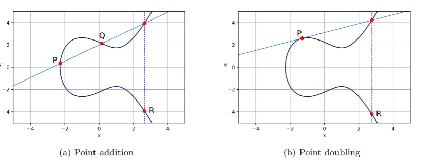
E forms an abelian group for specific values ofaandband when the point at infinityOis added to it. Since E is now commutative, associative and has an identity element and an inverse for each element by definition,E can be used as a discrete logarithm group for public key cryptosystems [59]. For points P = (x1, y1), Q = (x2, y2) ∈ F2n where P, Q 6= O, we can compute point addition
R= (x3, y3) =P+Qas follows:
x3=λ2+λ+x1+x2+a
y3=λ(x1+x3) +x3+y1
(2.23)
where in the case ofP 6=±Q, we define λas [21]:
λ= y2+y1 x2+x1
(2.24)
We refer to the case whereP =Qas point doubling. In this caseλis computed as [21]:
λ=x1+
y1
x1
(2.25)
Also, a pointP = (x1, y1) can be negated as follows [43]:
−P = (x1,−y1) (2.26)
Scalar point multiplication in the form ofR =mP, wherem ∈N, can be done using a repeated
combination of point addition and point doubling, called the double-and-add method, which is similar to the square-and-multiply algorithm. For example, R = 11P can be computed as R = 2(2(2P) + P) +P [59].
CHAPTER 2. BACKGROUND 2.3. BASIC CRYPTOGRAPHIC PROTOCOLS
4 2 0 2 4
x 4
2 0 2 4
y
P
Q
R
(a) Point addition
4 2 0 2 4
x 4
2 0 2 4
y
P
R
[image:15.595.101.523.77.233.2](b) Point doubling
Figure 2.1: Operations on curvey2=x3−3x+ 5
In Figure 2.1a, pointR=P+Q is obtained by drawing a line throughP andQ, extracting the third point of intersection with the elliptic curve and reflecting this point on the x-axis. In Figure 2.1b, pointR= 2P is obtained by drawing the tangent line ofP on the curve, extracting the second point of intersection with the curve and reflecting this point on the x-axis.
2.2.3.1 EC-ElGamal
In this work, we use EC-ElGamal, i.e. elliptic curve based ElGamal. We can describe the additively homomorphic EC-ElGamal cryptosystem as follows [43]:
Given a Galois fieldF2m with generator G, orderq, curve E, secret key a∈R Zq and public key
H=aG, we can define the encryption function for EC-ElGamal on a messagem∈Zq as:
C= (P, Q)←(rG, mG+rH) (2.27)
wherer∈RZq.
The decryption function on a ciphertextC= (P, Q) can now be defined as:
mG←Q−aP (2.28)
Observe that from the decryption function, we cannot retrieve message m due to the discrete logarithm problem, similar to the additively homomorphic version of plain ElGamal, where m is encoded asgm.
The additions and multiplications in the encryption and decryption function can be done using point additions, negations and scalar point multiplications as described in the previous section.
Despite the fact that in this work we use additively homomorphic EC-ElGamal, we continue to use the additively homomorphic ElGamal notation as described in Section 2.2.1 for simplicity purposes. However, the use of terms as multiplications and additions in the context of EC-ElGamal and ElGamal might be confusing, since they have different meanings in both contexts. We therefore use the terms
scalar point multiplicationandpoint additionwhen dealing with EC-ElGamal andscalar multiplication
andhomomorphic addition when dealing with ElGamal. Also note that in the context of additively homomorphic ElGamal we use the terms scalar multiplication and ciphertext multiplication, and homomorphic addition and ciphertext multiplication interchangeably.
2.3
Basic Cryptographic Protocols
In this section, we explain the two most fundamental cryptographic protocols used in this work: commitment schemes (Section 2.3.1) and zero-knowledge proofs (Section 2.3.2).
2.3.1
Commitment Schemes
2.3. BASIC CRYPTOGRAPHIC PROTOCOLS CHAPTER 2. BACKGROUND
words, reveals her message. Then, Bob can verify whether the message sent by Alice was originally constructed by her [19, 29].
More formally, we can define a commitment scheme as follows [7]:
Definition 7. First of all, assume that a group G of prime order for which the discrete logarithm problem is hard has been established. Now a commitment scheme should contain the following three algorithms:
• pk←KeyGen(1`): Key generation algorithmKeyGenwith input 1`, where`is a security param-eter, produces a public keypkused for the commitment.
• (c, d)←Com(pk, m, r): Using public keypk and a randomnessr, commitment algorithmCom
generates a commitment upon messagem∈ M, where Mis the message space in the current context. Additionally, it produces decommitment messaged= (m, r). For simplicity purposes, we will disregard input valuepkfrom here on.
• {accept,reject} ←Verify(pk, c, d, m): Verification algorithm Verifyhas as input public keypk, a commitmentc, decommitment messagedand messagem and returnsacceptor reject.
Moreover, a commitment scheme should have the binding and hiding properties. Binding means that the party who committed to a certain value cannot change this value anymore. Hence, when the value is revealed, we can be certain that this is the same value the party originally chose [19]. More formally, we can write the binding property as follows [62]:
Definition 8. A commitment scheme is computationally (resp. perfectly) binding if a computa-tionally bounded (resp. unbounded) adversary creates a commitment c for message m ∈ M1 and
randomness r ∈ M2 and is unable to find an m0 ∈ M1 (m0 6=m) and a randomness r0 ∈ M2 for
which the following holds:
Com(m, r) =Com(m0, r0) (2.29)
Schematically, we can represent the binding game as follows [62]:
Adversary Challenger
Input: m∈ M1, r∈ M2,(c, d)←Com(m, r)
m, r, c
−−−−−−−−→
m0 ∈ M1 (m0 6=m)
r0∈ M2
c0=Com(m0, r0)
m0, r0
−−−−−−−−→
Output:
(
[image:16.595.64.561.444.596.2]A wins, ifCom(m, r) =Com(m0, r0) A loses, otherwise
Figure 2.2: Binding game of a commitment scheme
Hiding means that Bob is unable to know the value which has been committed by Alice [19], or in other words, the value committed by Alice is indistinguishable from another committed value [62]. More formally, we can write the hiding property as follows [62]:
Definition 9. A commitment scheme is computationally (resp. perfectly) hiding if an adversary is able to win the following game:
• The adversary computes messagesm0, m1∈ M1of the same length.
• The challenger produces randomnessr∈RM2 and bitd∈R{0,1}.
• The challenger computes commitmentc=Com(md, r) and sendscto the adversary.
CHAPTER 2. BACKGROUND 2.3. BASIC CRYPTOGRAPHIC PROTOCOLS
Schematically, we can represent the hiding game as follows [62]:
Adversary Challenger
m0, m1∈ M1 (|m0|=|m1|)
m0, m1
−−−−−−−−−−→
r∈RM2, b∈R{0,1} c←Com(mb, r) c
←−−−−−−−−−−
b0 ∈ {0,1}
b0
−−−−−−−−−−→
Output: b0 Output:
(
[image:17.595.127.484.103.258.2]A wins, ifb0=b A loses, otherwise
Figure 2.3: Hiding game of a commitment scheme
Essentially, perfectly binding or hiding means that no computational resources exist to break the commitment scheme. In the same way, computational hiding or binding means computational resources exist to break the commitment scheme. However, we consider these resources to be extremely expensive in terms of efficiency, therefore, the probability to break the commitment scheme in case of computational hiding or binding is negligible [19].
Pedersen Commitment Scheme In this work, we use a commitment scheme as constructed by Pedersen [55].
Assume that the Pedersen commitment scheme works over groupG ⊆Z∗
pwith orderqand generator g, wherepandqare prime andq|p−1 applies. The commitment algorithms can now be instantiated as follows:
KeyGen(1`) =h (2.30)
wherehhi=G.
Com(m, r) =gm·hr (2.31)
wherem∈Zq andr∈RZq.
Verify(pk, c, d, m) :Com(d)=? c (2.32)
The Pedersen commitment scheme is computationally binding due to the hardness of the discrete logarithm problem and perfectly hiding, because the commitment is uniformly distributed overG, i.e. different sets of (m, r) exist that satisfy the commitment [22].
2.3.2
Zero-Knowledge Proof-of-Knowledge
A zero-knowledge proof-of-knowledge in cryptography is used where a party (prover) needs to prove to another party (verifier) that it knows a certain value, called a witness, without revealing anything but the fact that the prover possesses this knowledge.
2.3.2.1 Σ-Protocol
2.3. BASIC CRYPTOGRAPHIC PROTOCOLS CHAPTER 2. BACKGROUND
Definition 10. Letπ be a two-party protocol between a prover and a verifier, where the verifier is probabilistic polynomial time bounded, and letR be a binary relation whereR ⊂ {0,1}∗× {0,1}∗. Then protocol π is a Σ-protocol for Rwith challenge setC, common inputy and private witnessw for the prover, if and only if it holds the following properties:
• πis a3-move protocol as follows:
– The prover computes a commitmentt and sendstto the verifier.
– The verifier chooses a challengec ∈ C with challenge lengthmand sendsc to the prover. mis denoted as the soundness parameter and we define the knowledge error ofπas 2−m.
– The prover computes a responsesand sendssto the verifier.
– The verifier outputsacceptorrejectbased on the combination of the commitment, challenge and response.
• Completeness: Ify, w∈ R, then the verifier accepts with probability 1−µ(n), where µ(n) is a negligible function on inputn∈N.
• Special soundness: There exists a probabilistic polynomial time knowledge extractor E with inputs protocol runsρ= (t, c, s) and ρ0 = (t0, c0, s0) for whicht=t0 andc6=c0 applies, and an outputw0 such that (y, w0)∈ R.
• Special honest-verifier zero-knowledge: There exists a probabilistic polynomial time simulatorS with inputsy ∈ L(R) and c∈ C that returns protocol transcript (t, c, s), whose distribution is computationally indistinguishable from accepting protocol transcripts which have been generated by genuine protocol runs.
An example of a Σ-protocol is the Schnorr’s Identification Protocol, which forms the building block of the zero-knowledge proofs used in this work and can schematically be represented as follows [19]:
Prover Verifier
Input: w∈Zq Common Input: y←gw k∈RZq
t←Com(k)←gk
t
−−−−−−−−−−−−−−−−−−−−→
c∈ {0,1}m c
←−−−−−−−−−−−−−−−−−−−−
s←k−cw∈Zq
s
−−−−−−−−−−−−−−−−−−−−→
[image:18.595.139.444.425.574.2]Output: gsyc=? t
Figure 2.4: Schnorr’s Identification Protocol
Similar to the Pedersen commitment scheme, assume that the Schnorr’s Identification Protocol works over groupG ⊆Z∗p with orderqand generatorg, wherepandqare prime and q|p−1 applies. The prover has witnesswas private input and claims that it knows the discrete logarithm of y, such that y←gw. RelationRis therefore defined as: R={((G, q, g, y), w)|y←gw}.
The protocol transcript can now be explained as follows:
• First, the prover computes commitmentt=Com(k) for a random k∈R Zq and sendst to the verifier.
• The verifier computes challengec∈ {0,1}m, wheremdenotes the level of soundness, and sends cto the prover.
• Subsequently, the prover computes responses←k−cw∈Zq and sends sto the verifier.
CHAPTER 2. BACKGROUND 2.3. BASIC CRYPTOGRAPHIC PROTOCOLS
2.3.2.2 Non-Interactive Zero-Knowledge Proofs
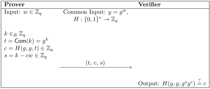
A Σ-proof with the special soundness property can be turned into a non-interactive zero-knowledge proof (NIZK) by applying the Fiat-Shamir Heuristic as follows:
Prover Verifier
Input: w∈Zq Common Input: y=gw, H :{0,1}∗→
Zq k∈RZq
t=Com(k) =gk c=H(g, y, t)∈Zq s=k−cw∈Zq
(t, c, s)
−−−−−−−−−−−−−−−−−−−−→
[image:19.595.132.477.136.283.2]Output: H(g, y, gsyc)=? c
Figure 2.5: Non-Interactive Schnorr’s Identification Protocol
The setup for the non-interactive Schnorr’s Identification Protocol is similar as in the previous section. However, the prover and verifier now also agree on a hash function H : {0,1}∗ →
Zq prior to the protocol. The prover computes t and sas in the previous section, but it now also computes challengecas the hash function of (g, y, t) and sends (t, c, s) to the verifier. The verifier computes the hash of (g, y, gsys) and checks if it equals c.
According to Bernhard et al. [8], two variants of the Fiat-Shamir heuristic are commonly used: the weak variant, in which only the commitment to the prover’s secret is included in the challenge and the strong variant, in which also the to be proved statement is included in the challenge. The strong variant has been proven to be secure against malicious verifiers in the random oracle model [8].
Chapter 3
Related Work
Several approaches have been constructed in the field of BTP schemes and other biometric protocols. First of all, in Section 3.1 we explain some state-of-the-art BTP schemes that are secure in the semi-honest model. In Section 3.2, we dive deeper into biometric protocols that are secure in the malicious model.
3.1
BTP schemes in the semi-honest model
Biometric Template Protection schemes can be divided into the following categories [38, 56]:
• Feature Transformations: In BTP schemes based on Feature Transformations, a (one-way) trans-formation function is applied on both the biometric template and the database template and the two templates are compared in the transformed domain [31,56]. The revocability property is satisfied, since a template can be re-issued when it is compromised by performing a transforma-tion functransforma-tion again [54]. BTP schemes based on Feature Transformatransforma-tions can be further divided into: BioHashing and Cancelable Biometrics. In schemes based on BioHashing, the transforma-tion functransforma-tion is invertible, which means that if an attacker obtains the transformatransforma-tion key and the transformed template, he can retrieve the original template [38]. Cancelable Biometrics are more secure than BioHashing, since cancelable biometrics are based on non-invertible transfor-mation functions, although the scheme still struggles with a trade-off between non-invertibility and accuracy [38, 56]. Examples of secure and efficient implementations based on Cancelable Transformations, are the works of Sadhya et al. [58], Gomez-Barrero et al. [32] and Martiri et al. [48], which proposed and implemented BTP schemes based on bloom filters. Schemes based on Bloom filters transform unprotected templates into bloom filter sets using irreversible transformation functions [32]. Bloom filter-based approaches allow for better template security, biometric data compression and efficient verification of templates [57].
• Biometric Crypto-Systems: In Biometric crypto-systems, templates are transformed in such a way that they resemble the original template of that user using error-correction coding tech-niques. Biometric crypto-systems do not satisfy non-invertibility, accuracy and revocability [56].
CHAPTER 3. RELATED WORK 3.2. BIOMETRIC PROTOCOLS IN THE MAL. MODEL
encryption, but is focused on multi-biometric template protection (MBTP) schemes. Multi-biometric refers to the comparison of multiple Multi-biometrics of the same subject in order to achieve a higher accuracy. The work of Gomez-Barrero et al. [31] is the first MBTP scheme that uses homomorphic encryption.
Finally, also secure and efficient systems in which new encryption and matching techniques are used, such as the work of Zhang et al. [66], which provides an approach to a cloud-based biometric authentication system. In this protocol, a database owner retrieves encrypted templates from the cloud server and performs the comparison operation. It is assumed that the cloud server is semi-honest, and that the database owner and the user can be malicious. Because of their cloud server, Zhang et al. [66] claims stronger security than similar schemes. Additionally, their scheme is secure against collusion between the client and the cloud server. However, since the cloud server is assumed to be at most semi-honest, the scheme of Zhang et al. is still not completely secure in the malicious model. We expect that extending the work of Zhang et al. [66] to the full malicious model will be harder than for other schemes, since their approach is a three-party protocol, instead of a two-party protocol.
3.2
Biometric protocols in the malicious model
The BTP schemes previously mentioned are not secure against malicious attackers, however. In the work of Bringer et al. [16], a two-party computation protocol for computing metrics (e.g. Hamming distance), called GSHADE, is extended to be secure against malicious attackers. First of all, GSHADE is extended to GSHADE×to evaluate functions in the formfx(X, Y) =fX(X)×fy(Y)×Q
n
i=1fi(xi, Y).
Secondly, GSHADE+, an existing protocol which is the additive variant of GSHADE×, is made secure against malicious attackers resulting in GSHADE. In GSHADE, a dual execution is performed, where two parties simultaneously execute the GSHADE+ protocol, switching roles between the two
executions. Subsequently, they perform a secure equality test to check whether the two protocol executions were executed correctly. Additionally, GSHADE× is also made secure against malicious attackers by transforming GSHADE accordingly, resulting in GSHADE. Finally, Bringer et al. [16] concludes that the performance of GSHADE and GSHADE is better than alternatives, such as cut-and-choose techniques [16]. Since GSHADE and GSHADE are secure methods to compute metrics, they can be used in biometric verification systems based on e.g. the Hamming or Euclidean distance.
Chapter 4
Semi-Honest Protocol
The biometric verification protocol of Peeters et al. [56] forms the basis of this work. Hence, we will first explain the structure of the templates used in the work of Peeters et al. [56] in Section 4.1 and then explain its protocol briefly in Section 4.2.
4.1
Template Structure
A biometric template is a structure containing similarity scores which can be selected for verification purposes. A template is constructed as follows. When a user presents its biometric identifier to the enrollment party, ak-dimensional feature vector~pis created. The features are quantized over 2b bins, to limit the number of features. For each feature, a 2b×2blookup tableT
b,ρis constructed containing all possible partial similarity scoressx,y between two users for that feature. See Equation 4.1 below.
Tb,ρ=
s0,0 s0,1 · · · s0,2b−1
s1,0 s1,1 · · · s1,2b−1
..
. ... . .. ... s2b−1,0 s2b−1,1 · · · s2b−1,2b−1
(4.1)
Partial similarity scores are added in a later stage to obtain a single similarity score, which de-notes the level of affinity between two biometric identifiers. Partial similarity scores are precomputed using a log-likelihood ratio classifier. To enable encryption of partial similarity scores, they are quan-tized to natural numbers using uniform quantization function q∆ : R → N with step size ∆ on
score domain [min(s),max(s)]. We denote the total score distribution byS and its score domain by
[min(S),max(S)] = [Pk−i=01min(si),
Pk−1
i=0 max(si)].
For each pi, the row containing the similarity scores of pi with other users in the corresponding lookup table is selected and included in templateTu as follows [56]:
Tu=
T(p0) b,ρ0
>
| T(p1) b,ρ1
>
| · · · | T(pk−1) b,ρk−1
>>
(4.2)
NowTu is a 2b×kmatrix containing all the partial similarity scores for feature vector~pwith any other feature vector.
Since details on the construction of the partial similarity scores and the templates are out of scope for this research, we highly recommend interested users to read the work of Peeters et al. [56] for further specifics.
4.2
Protocol
The biometric verification protocol of Peeters et al. [56] consists of an enrollment procedure and a verification procedure. We will explain these procedures in Section 4.2.2 and 4.2.3, respectively. However, we first explain how the key setup is done, since this is an important part of the system.
4.2.1
Key Setup
CHAPTER 4. SEMI-HONEST PROTOCOL 4.2. PROTOCOL
consisting of public keyPKand secret keysk. However, in the work of Peeters et al. [56], a threshold version of ElGamal is used, which prevents parties from decrypting a ciphertext and thus leaking a template. The key setup protocol is depicted in Figure 4.1. Note that in the original semi-honest protocol by Peeters et al. [56], the key setup and (partial) decryption is done in a slightly different manner.
Sensor Device Server
hgi=G ⊆Z∗
p (p, q∈P, q|p−1)
(pkss,skss)←GenerateKey() (pksv,sksv)←GenerateKey()
pkss
−−−−−−−−−−−−−−−−−−−−−−−→
pksv
←−−−−−−−−−−−−−−−−−−−−−−−
[image:23.595.91.519.152.242.2]pkshared←(pksv)skss pkshared←(pkss)sksv
Figure 4.1: Adapted key setup for semi-honest protocol by Peeters et al. [56]
Similar to the Diffie-Hellman key exchange protocol, the sensor and server first agree on a common groupG ⊆Z∗
pwith generatorgand prime orderqforp, q∈Pandq|p−1. Then they send their public keys over an established communication channel to each other. Subsequently, they both compute a shared public key by exponentiating the public key received from the other party with their own secret key.
As mentioned in Section 2.1.1, a message m, which has been double-encrypted under a shared public keypkshared, is denoted by [[m]]. A party with secret keysk1can partially decrypt a ciphertext
[[m]]pkshared by performing a partial decryption functionD1, which is computed as follows:
D1([[m]]) =D1(c1, c2) = (c1sk1, c2) = (c01, c02) = [m] (4.3)
As a second decryption step by the other party holding secret key sk2, the default ElGamal
decryption function, in this work denoted byD2, can be performed as follows:
D2([m]) =D2(c01, c
0
2) =c
0−sk2
1 ·c2
=c−sk1·sk2
1 ·c2= (gr)−sk1·sk2·m·(pkshared) r =pk−rshared·m·(pkshared)
r =m
(4.4)
4.2.2
Enrollment Procedure
Before the sensor device and the verification server can engage in the biometric verification protocol, a useruusing the sensor device needs to be enrolled to the system first. We describe the protocol for the enrollment phase as follows.
Enrollment Party Server
(1)u,Tu←Capture() (2) [[Tu]]←E(Tu)
(3) −−−−−−−−−−−−−−−−−−→(u,[[Tu]])
(4)StoreTable((u,[[Tu]]))
Figure 4.2: Semi-honest enrollment protocol by Peeters et al. [56]
Protocol Description:
[image:23.595.119.486.591.663.2]4.2. PROTOCOL CHAPTER 4. SEMI-HONEST PROTOCOL
Step 2-3: Then, the enrollment party encrypts the template element-wise usingpkshared and sends (u,[[Tu]]) to the server. However, before encryption, the enrollment party encodes the elements as exponents of generator g to enable addition of similarity scores in a later stage. We refer back to Section 2.2.2 for more information.
Step 4: The server stores the tuple in its database for later retrieval.
4.2.3
Verification Procedure
When a user has been enrolled to the system, the system can verify the user’s identity by having the sensor device it uses and the verification server engage in the verification procedure, which is depicted schematically in Figure 4.3.
Sensor Device Server
(5)u, ~p←Capture()
(6) −−−−−−−−−−→u
(7) [[Tu]]←FetchTemplate(u) (8) ←−−−−−−−−−−[[Tu]]
(9) [[~s]]←LookUp(~p,[[Tu]]) (10) [[S]]←[[0 +
k−1
X
i=0
si]]
(11) −−−−−−−−−−→[[S]]
(12) [[C]]~ ←Compare([[S]], t) (13)π([[C]])~
(14) [C]~ ←D1([[C]])~
(15) [ ~ C]
←−−−−−−−−−−
(16)C~ ←D2([C])~
[image:24.595.102.480.235.474.2](17)∃Ci:Ci= 0 =⇒S≥t
Figure 4.3: Semi-honest verification protocol by Peeters et al. [56]
Protocol Description:
Step 5: In the verification procedure, a sensor device constructs a quantized probe vector ~pfrom the biometric data it captures from useru.
Step 6-8: The sensor device then makes a request for template [[Tu]], which the server fetches from its database.
Step 9: For each featurepi, a partial similarity score [[si]] is looked up in [[Tu]].
Step 10: Subsequently, these partial similarity scores are added in a homomorphic way to obtain [[S]] as explained in Section 2.2.2. Since ElGamal is probabilistic, [[0]] is added to the summation to randomize the outcome.
Step 11: Finally, the result is sent to the verification server.
CHAPTER 4. SEMI-HONEST PROTOCOL 4.2. PROTOCOL
[[C]] = [[~ {ri(S−t−i)| ∀0≤i≤max(S)−t, ri∈RZq}]] (4.5) whereriis a blinding value which protects the results in [[C]].
Step 13: To remove ordering, a permutation functionπ([[C]]) is performed to randomize the results in [[C]].
Step 14-15: The verification server partially decrypts [[C]] using~ sksv and sends the resulting [C]~ to the sensor device.
Chapter 5
Semi-Honest Key Release Protocol
In this chapter, we will answer the following research question:
RQ1 How can we adapt the approach by Peeters et al. [56] in such a way that a key is released upon successful verification instead of a simple ”yes” or ”no”?
First of all, in Section 5.1, we describe the structure of the so-called semi-honest key release protocol that we created in this chapter and finally, in Section 5.2, we elaborate on the design choices we made.
5.1
Protocol
In this section, we first present two requirements that the semi-honest key release protocol should satisfy (Section 5.1.1). Subsequently we describe how we constructed the enrollment phase (Section 5.1.3) and the verification procedure (Section 5.1.4) of the semi-honest key release protocol.
5.1.1
Requirements
Let the key that is released by the semi-honest key release protocol be denoted byK. Now we establish the following set of requirements that the semi-honest key release protocol should adhere to:
1. The verification server should not be able to learn anything about keyK.
2. Kshould be consistent for every biometric probep~belonging to the same identityu.
5.1.2
Key Setup
The key setup is similar to the key setup of the semi-honest protocol by Peeters et al. [56] as explained in Section 4.2.1. Recall that the server and sensor first agree on a common groupG ⊆Z∗
pwith generator g and prime orderqforp, q∈Pandq|p−1. Subsequently, they send their public keys to each other and compute the shared public key by exponentiating the public key received from the other party with their own secret key.
5.1.3
Enrollment Procedure
First, we describe the protocol for the enrollment phase as can be seen in Figure 5.1.
Enrollment Party Server
(1)u,Tu←Capture() (2) [[Tu]]←E(Tu) (3)K←gk |k∈
RZq (4) [[k]]←E(k) (5)AESK(1)
(6) −−−−−−−−−−−−−−−−−−−−→(u,[[Tu]],([[k]],AESK(1)))
[image:26.595.71.508.647.756.2](7)StoreTable(u,[[Tu]],([[k]],AESK(1)))
CHAPTER 5. SEMI-HONEST KEY RELEASE PROTOCOL 5.1. PROTOCOL
In the enrollment phase, we have added the following functionalities as compared to the work of Peeters et al. [56]:
Step 3-4: The enrollment party randomly generates an integerk∈RZq, and encodesk asK=gk,
which is the representation of the key released upon successful verification. Subsequently, the enroll-ment party encryptsK using ElGamal. Recall that in this work, we use an additively homomorphic version of ElGamal, i.e. we first encode plaintext values as powers of generatorg before encryption. SinceK←gk, we will denote the ElGamal encryption ofK by [[k]] = (gr, gk·hr).
Step 5: The enrollment party encrypts the value 1 with keyKusing AES. This encryption is used later in the verification process at the sensor side to check whether it has received a valid key.
Step 7: The verification server stores ([[Tu]],[[k]],AESK(1)) under keyuin a database.
5.1.4
Verification Procedure
Secondly, we describe the protocol for the verification procedure as can be seen in Figure 5.2.
Sensor Device Server
(8)u, ~p←Capture()
(9) −−−−−−−−−−→u
(10) [[Tu]]←FetchTemplate(u) (11) ←−−−−−−−−−−[[Tu]]
(12) [[~s]]←LookUp(~p,[[Tu]]) (13) [[S]]←[[0 +
k−1
X
i=0
si]]
(14) −−−−−−−−−−→[[S]]
(15) [[C]]~ ←Compare([[S]], t) (16)π([[C]])~
(17) ([[k]],AESK(1))←FetchKey(u) (18) [[B]]~ ←[[C]]~ ·[[k]]
(19) [B]~ ←D1([[B]])~
(20) ([ ~
B],AESK(1))
←−−−−−−−−−−
(21)B~ ←D2([B])~
(22)∃Bi:AES-DBi(AESK(1)) = 1
[image:27.595.83.519.298.561.2]=⇒S≥t
Figure 5.2: Semi-honest verification protocol by Peeters et al. [56] extended with key release
In the verification phase, we have added the following functionalities as compared to the work of Peeters et al. [56]:
Step 17: Using identityu, we fetch [[k]] from the database.
Step 18: Similar to the encryption of [[k]], the plaintext elements of [[C]] are encoded as powers~ ofg. We multiply the encrypted comparison score vector [[C]] with [[k]], obtaining [[~ B]], which is its~ homomorphic addition.
5.2. DESIGN CHOICES CHAPTER 5. SEMI-HONEST KEY RELEASE PROTOCOL
Note that key revocation in this system is possible and straightforward, since [[k]] and AESK(1) are stored in the database at Step 7 and can easily be updated if the sensor device sends an update query to the verification server. Also, note that Step 10 and Step 17 could be concatenated in the implementation by fetching [[Tu]], [[k]] and AESK(1) in one query. However, we decided to maintain two database queries for clarity purposes.
5.1.5
Proof of Security, Correctness and Requirements
Although keyKis random for each protocol emulation, we treat the semi-honest key release protocol as a deterministic protocol, since the output is either 0 orKand does not change in the case of multiple runs with the same biometric sample. As mentioned in Section 2.1.3.1, for proving a deterministic protocol is secure in the semi-honest model, we need both a proof of security and correctness. For the proof of correctness and security, we refer to Appendix A and B, respectively. Furthermore, see Appendix C for a proof that the semi-honest key release protocol meets the requirements as stated in Section 5.1.1.
5.2
Design Choices
In this section, we describe how we designed the system and which parameters we used for the protocols and schemes.
Communication A server should be able to maintain connections with multiple clients at the same time. However, for simplicity purposes, we implemented the protocol such that there is only one connection between a server and a client and the client resembles both the enrollment party and the sensor device.
Discrete Logarithm Group For the underlying discrete logarithm group, which is used for the ElGamal encryption system, we use elliptic curves for their performance benefits over groups that are directly based prime integers, as mentioned before in Section 2.2.3. More specifically, we have chosen the K-233 curve as selected by NIST for the efficiency benefits of Koblitz curves over other elliptic curves [41, 42]. The K-233 curve provides a security level of 112 bits [5]. See Table 5.1 for an overview of the parameter selection of K-233.
Parameter Selection
T 2
p(t) t233+t74+ 1
a 0
q 3450873173395281893717377931138512760570940988862252126328087024741343 Gx (polynomial basis) 172 32ba853a 7e731af1 29f22ff4 149563a4 19c26bf5 0a4c9d6e efad6126
Gy (polynomial basis) 1db 537dece8 19b7f70f 555a67c4 27a8cd9b f18aeb9b 56e0c110 56fae6a3 Gx (normal basis) 0fd e76d9dcd 26e643ac 26f1aa90 1aa12978 4b71fc07 22b2d056 14d650b3 Gy (normal basis) 064 3e317633 155c9e04 47ba8020 a3c43177 450ee036 d6335014 34cac978
Table 5.1: Parameter choices for K-233 NIST elliptic curve, whereT is the normal basis type,p(t) the field polynomial,athe coefficient,qthe order, and (Gx, Gy) the hexadecimal coordinates of generator pointGin the polynomial and normal basis, which are two different ways to represent a field [41]
Template Construction Since the focus of this work is on the security of the biometric verification system, rather than on the biometrics part as in the work of Peeters et al. [56], we decided not to compute lookup tables first and then construct a template based on these lookup tables. Alternatively, we simulate a templateTwith size (2b, k) by choosing the partial similarity scores it contains uniformly at random from the score domain [min(s),max(s)]. We have setmin(s) = 0 andmax(s) to a random positive integer, depending on the performance tests we did (see Chapter 8). Recall that the total score distribution is denoted byS. We have setmin(S) = 0 andmax(S) =max(s)·k, since the probe
vectorp~in the verification phase selectsk partial similarity scores from the template. We encrypt a template by encrypting its similarity scores element-wise.
CHAPTER 5. SEMI-HONEST KEY RELEASE PROTOCOL 5.2. DESIGN CHOICES
Chapter 6
Partially Malicious Key Release
Protocol
In this chapter, we answer the main research question:
RQ2 How can we adapt the key release protocol in such a way that it is secure in the setting where the sensor device is (semi-)honest and the server is malicious?
First of all, in Section 6.1, we explain the building blocks needed to understand some of the parts of the partially malicious key release protocol. Then, in Section 6.2 we explain how we constructed the partially malicious key release protocol, give a security proof and finally in Section 6.3, we elaborate on the design choices we made.
6.1
Building Blocks
In this section, we present the four main building blocks of the partially malicious key release proto-col: The GMW compiler (Section 6.1.1), an equality of exponents proof (Section 6.1.2), the Schnorr Signature Scheme (Section 6.1.3) and a permutation proving scheme (Section 6.1.4).
6.1.1
GMW Compiler
Goldreich et al. [28, 30] proposed an approach to transform a semi-honest secure protocol into a maliciously secure protocol, called the GMW compiler. Parties run a semi-honest protocol, but due to zero-knowledge proofs they can prove they executed the protocol correctly and thus the protocol is secure against malicious attackers. In essence, parties are enforced to behave in a semi-honest way. Compiling the semi-honest secure protocol to a maliciously secure protocol can be done in polynomial time.
We will not strictly follow the GMW compiler to obtain the partially malicious key release protocol as designed in this chapter, but we will use its Augmented Coin Tossing (ACT) protocol. Moreover, we will rely on the security of the GMW compiler to come to an argumentative security proof for the partially malicious key release protocol. See Appendix E for more details.
6.1.1.1 Preliminary Functionalities
Before we explain the protocol, let us first define some preliminary functionalities needed for the GMW compiler: the Basic Coin Tossing protocol, the Authenticated Computation protocol and the Augmented Coin Tossing protocol.


![Figure 4.2: Semi-honest enrollment protocol by Peeters et al. [56]](https://thumb-us.123doks.com/thumbv2/123dok_us/9592424.462784/23.595.91.519.152.242/figure-semi-honest-enrollment-protocol-by-peeters-al.webp)
![Figure 4.3: Semi-honest verification protocol by Peeters et al. [56]](https://thumb-us.123doks.com/thumbv2/123dok_us/9592424.462784/24.595.102.480.235.474/figure-semi-honest-verication-protocol-peeters-et-al.webp)
![Figure 5.1: Semi-honest enrollment protocol by Peeters et al. [56] extended with key release](https://thumb-us.123doks.com/thumbv2/123dok_us/9592424.462784/26.595.71.508.647.756/figure-semi-honest-enrollment-protocol-peeters-extended-release.webp)
![Figure 5.2: Semi-honest verification protocol by Peeters et al. [56] extended with key release](https://thumb-us.123doks.com/thumbv2/123dok_us/9592424.462784/27.595.83.519.298.561/figure-semi-honest-verication-protocol-peeters-extended-release.webp)