Stability and Mobility of Interstitial-Type Defect Clusters
Generated from Displacement Cascades in Copper and Gold
by
In-Situ
Transmission Electron Microscopy
Hiroaki Abe
1;2*, Naoto Sekimura
2and Tadayasu Tadokoro
21Research Center for Nuclear Science and Technology, University of Tokyo, Tokai, Ibaraki 319-1188, Japan
2Department of Quantum Engineering and Systems Science, University of Tokyo, Tokyo 113-8656, Japan
In-situTEM observations were carried out in copper and gold under 100 keV Cþ, 240 keV Cuþ, 600 keV Kr2þ, and 900 keV Xe3þ
irradiations from 573 to 823 K, in order to obtain direct experimental insights into the defect accumulation processes. Defect clusters corresponding to displacement cascades were observed to be unstable depending on the temperature, ion species, and fluence. Multiple (2 or 3) defect clusters showing up with their contrast in the same video frames were considered to be features associated with subcascades and high mobility of these clusters when located within 20 nm and from 20 to 140 nm, respectively. Instability and diffusion of defect clusters were also detected under ion irradiation. The directions of the cascade-driven and instability-driven motions of the defect clusters were strongly related to crowdion directions, suggesting that the underlying mechanism is based on the motion of crowdion-related glissile defects. This instability is interpreted as the transition of sessile defects into glissile ones. The effects of intra- and inter-cascades on the formation of glissile defects are suggested based on their dependence on the ion species and flux.
(Received September 27, 2004; Accepted December 15, 2004)
Keywords: transmission electron microscopy, in-situ observation, ion irradiation, displacement cascades, copper, gold
1. Introduction
Energetic particles, such as ions and neutrons, transfer a portion of their energy to lattice atoms in the form of kinetic energy; this leads to lattice displacements. When kinetic energy of more than a few keV is transferred to a primary knock-on atom, dense displacements, so-called a displace-ment cascade is generated from a local volume of the order of
103 to 104 atoms. According to molecular dynamic (MD)
simulations,1,2) a volume can be locally and spontaneously
melted and rapidly cooled to leave vacancies and interstitial atoms. The defect clusters may therefore be formed after the cooling phase and can be simultaneously observed with a transmission electron microscope interfaced with an ion accelerator (TEM-Accelerator).3–5)This method is referred to
as the indispensable method. The simultaneous observations of the accumulation process and the instability of defect clusters under ion irradiations revealed that the fraction and size of surviving defects depend on irradiation conditions, such as incoming particles and temperature.6–13) In-situ
observations using high-voltage electron microscopes are also indispensable in detecting the motion of defect clusters in metals.14,15) The motion suggests that dislocation loops
transform into mobile defects enabling diffusion with relatively low activation energy; however, its mechanism has not yet been experimentally clarified. Recently conducted MD simulations have revealed the generation of glissile defects consisting of crowdions in displacement cascades in Cu and Fe.16,17)The glissile defects are capable of traveling
large distances in the crowdion directions,i.e.,h110i in fcc and h111i in bcc. The activation energy is estimated to be extremely small, below 0.04 eV, which is even smaller than the binding energy of the defects and the migration energy of single interstitials.18)The MD simulation results indicate that
the crowdion-related interstitial-type defect clusters can be formed within displacement cascades, and they are able to diffuse rapidly but are unstable especially at relatively high temperatures. Evidently, there is no report that verifies the existence of interstitial-type defects in copper and gold at temperatures above 500 K; however, our recentin-situTEM observations have provided evidence for these defects even at temperatures of 700 K and above.19)However, the
character-istics of the glissile defects and related cascade effects are still unclear.
In this work, we present simultaneous microscopic observations under ion irradiations using the TEM-Accel-erator facility, in order to reveal the formation, stability, and nature of mobile (glissile) defect clusters as well as to obtain an insight into inter- or intra-subcascade effects on the glissile defect clusters.
2. Experimental Procedures
Pure copper (>99:999%) and pure gold (99.99%) were separately annealed at 1000 K for 12 h in Ar-3% H2gas flow
and in air, respectively; they were then cut into disks of 3 mm in diameter. Subsequently, to achieve electron-transparent thin foils, the Cu and Au specimens were electrochemically perforated in a solution of 30% nitric acid in methanol at 20 V and 277 K and in 1 mol LiCl in methanol at 30 V and 300 K, respectively.20)Prior to the irradiation, samples were set in
TEM and annealed at 773 K or above to stabilize the surface morphology during irradiation at high temperatures. This was done because of the presence of a rather high vapor pressure in vacuum and the irradiation-enhanced evaporation of the samples. Samples whose surface normal was close to {011} were taken to achieve stable surface morphologies,21)and in several cases, in-situ observations in {001} samples were carried out. The samples were then irradiated with ions in a TEM (JEM-4000FX, JEOL Ltd.) with ion accelerators, *Corresponding author, E-mail: [email protected]
installed at Takasaki Ion Accelerators for Radiation Appli-cation (TIARA), at the Japan Atomic Energy Research Institute (JAERI), Takasaki, Japan.5,22)Irradiation in copper was performed with either 100 keV Cþions and a current of
2:51013C/cm2s or 240 keV Cuþions and5:11011Cu/
cm2s, while that in gold was performed at either 600 keV Kr2þ ions and a current of5:11010 Kr/cm2s or 900 keV Xe3þ and a current of9:81010 Xe/cm2s, at temperatures
ranging from 573 to 823 K. The beam transport was carefully tuned using a mass analyzing magnet, a bending magnet, two sets of electrostatic prisms, and an einzel lens with the aid of a set of beam slits, a beam attenuator, a set of beam shifters, and a set of beam scanners so as to achieve a well-aligned and stable beam with a low-divergence at the sample position in TEM. The beam area for the sample is roughly 1.5 mm in diameter, and beyond this, the beam intensity is mostly identical. The beam current is measured using a Faraday cup with an entrance aperture diameter of 0.25 mm at the level of the specimen. Considering the irradiation geometry, wherein the angle between the ion beam and the sample normal is 30 degrees, the projected ranges from the sample surface were estimated by TRIM (or SRIM) calculations.23) In copper, these ranges corresponded to 115 and 57 nm for 100 keV Cþ
and 240 keV Cuþ ions, respectively. Since the thickness of
the observed regions is typically 50–70 nm, approximately 81–89% and 31–58% of the incoming Cþ and Cuþ ions
penetrate the sample, respectively. For Kr2þand Xe3þions in
gold, the projected ranges are 87 and 85 nm, and the portions of transmitted ions for a 50-nm-thick foil are 80% and 78%, respectively. Microstructural evolution was observed at the TEM operation voltage of 400 kV mainly by the weak-beam dark-field (WBDF) technique at the conditions ofn¼ ½011, g¼200,g(4–6g). The imaging system (Gatan Inc., model 676) consists of a YAG scintillator screen that is fiber-optically coupled to an image intensifier and further coupled to a conventional TV-rate CCD (frame rate of 1/30 s). An image of the sample, approximately equivalent to
108nm140nm, was videotaped without image processors so as to achieve the maximal time resolution. The effect of remanence of the scintillator is not experimentally detected in the system. The only two parameters that were processed by a computer after image acquisition were contrast and the brightness of each frame.
3. Results and Discussion
3.1 Evolution of displacement cascades
The defect contrast features appeared and were observed as dots or black-and-white contrast features. The diameter of these defect contrast features ranged from 4 to 6 nm, as shown in Fig. 1. The defects are presumed to be either vacancy-type dislocation loops, stacking fault tetrahedra (SFT), or interstitial-type dislocation loops. In copper, the probability of defect cluster formation was estimated to be 2% and 67% of the incoming particles for Cþ and Cuþ ion
irradiations, respectively. In gold irradiated with Kr2þ and
Xe3þ, this probability was approximately 70%. In addition to the single contrast feature, multiple (typically 2 or 3) contrast features appeared in the video frames, each of which was located within the distances range from 4 to 140 nm, as shown in Figs. 1(b) and (f). Since the magnification of TEM observations was fixed throughout the experiments, we could not detect features that were located more than 150 nm apart, which is approximately a diagonal of the measured area.
One characteristic feature of high-energy and heavy ion irradiation is the branching off of the displacement se-quences, forming multiple displacement-dense regions along the trajectory of ions; these are referred to as subcascades. The WBDF method employed in this work is a good measure to observe the subcascades since it enhances the contrast around the defects, resulting in a higher resolution for distinguishing closely located contrast features.24,25) The features located within a distance of 20 nm were regarded as defects generated from the subcascades.19)Multiple contrast
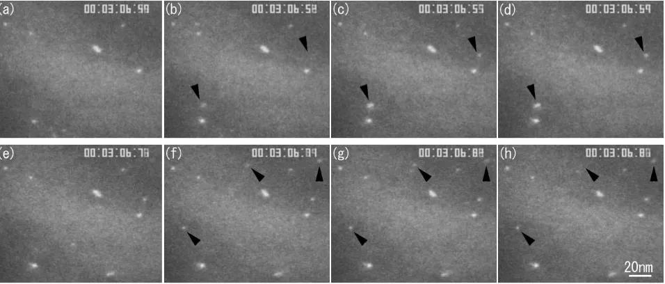
Fig. 1 Microstructural evolution in copper irradiated with 240-keV Cuþ ions at 828 K. Ion beam current for the sample is 40 pA/
0:25mm (5:11011ions/cm2s). The sequence is captured from videotapes with a time resolution of 1/30 s. The black arrows showing
[image:2.595.60.538.73.277.2]features appeared in single video frames and were character-istic of heavy-ion irradiations, while no subcascades have been detected from light ion irradiations such as carbon ions. The probability that multiple independent ions pass through and form defect clusters within such small areas is far smaller than detected. Although the flux for C-irradiation was more than double that of Cu and other heavy ions, this was notified only in heavy ion irradiations. The distances between the multiple defects agreed well with the estimation obtained from TRIM.19,26)
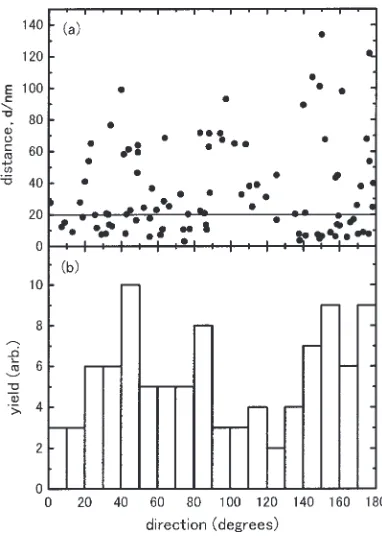
On the other hand, as indicated with arrows in Fig. 1, a large number of defects were evidently distributed over distances exceeding those expected from subcascade events. The phenomenon, hereafter referred to as multi-defect formation, can be hypothesized in either of the following ways: (i) the clusters are formed from independent ions, hereafter referred to as multi- (or 2-) particle event. (ii) The clusters are formed from an ion, and either or all clusters are capable of traveling by a diffusion mechanism that is currently undefined, hereafter referred to as single-particle event. Figures 2(a) and (b)19) show the distribution of
distance between the defect clusters appearing in the same video frame and the yield of directions, respectively. The direction was defined as counterclockwise in the segment between the two defects and as horizontal in the video frame. The data in the figure were accumulated for a total irradiation time of 10 min; however, due to a change in the TEM contrast, the net accumulation time, in this case, was less than 5 min. It should be noted that the distance and direction are
the ones projected on the imaging screen. The distance distribution ranges up to 140 nm, and the yield of directions is anisotropic, especially for features that encompass a diameter of more than 20 nm. The frequency of a 2-particle event in a region of, for example, 100 nm, is 0.80. However, the possibility of the multi-particle event (i) can be eliminated for the following reasons. One is that, as shown in Fig. 2(b), the anisotropic distribution of multi-defect events is evident. The three peaks in this figure are almost identical to the projections of the h110i crowdion directions. It should be noted that due to weak-beam conditions, the directions measured in this work approximately deviated by 5 to 10 degrees from the identical 011 pole. The difference in the yield at eachh110i-related peak could be influenced by the surface effects as well as by the reasons proposed by experiments, such as the limitation of the analysis area and the projection of three-dimensionally distributed clusters. In the case of the (001) gold sample, we detected two peaks in perpendicular directions along [110] and [1110]. The other reason is that the distance between such defects varies with the irradiation time.19) At the beginning of irradiation, the
distance is up to 140 nm and it decreases with an increase in the irradiation time. The fluence dependence of the formation rate was also detected. Based on these reasons, we conclude that the evolution of multi-defect formation in the same time bin (video frame) results from a single particle event.
3.2 Instability of defect clusters
All the defects eventually disappeared within seconds at the investigation temperature. Their lifetime depended on the incident particles, temperature, and irradiation fluence.19)The
typical feature of the lifetime is as follows. Defects generated from light ions disappeared in shorter lifetimes, typically lasting for less than 3 s. On the contrary, defects generating from heavy ones can have three lifetimes—less than 1 s, 3 to several seconds, and longer lifetime—each of which is found to be correlated with the nature of the defect clusters. A typical lifetime of SFT was several seconds or more, and that of the vacancy-type dislocation loops (V-clusters) was less than several seconds, as estimated in a previous work.10)In
addition to the above, we must note that tiny defects (a couple of nm) with much shorter lifetimes, lasting for several thirtieths of a second or less, were detected. These have not been previously reported, presumably because the WBDF technique enables higher spatial and time resolutions than those obtained by the bright-field technique. It should be noted that many of the defects were associated with the abovementioned multi-defect event. In Fig. 1, two defects, 100 nm apart, first appeared in (b) and then disappeared in 3/ 30 or 4/30 second. Similarly, two of three defects appeared in (f) and then disappeared in several thirtieths of a second.
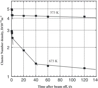
The above results were derived fromin-situobservations under ion irradiations. To confirm the thermal stability of the defects and to clarify the nature-dependent lifetime in gold, we performed post-irradiation thermal annealing experiments under the beam-off condition.8,10,11)This experiment consid-ers in-situ observations as a function of time after ion irradiation has been terminated. At the moment of beam off, nonfatal mechanical vibrations were induced from an insert of a Faraday cup for several thirtieths of a second. Image Fig. 2 Distribution of the multiple-defect clusters that appeared in the
same time bins (the same video frames) as a function of distance in (a) and angle in (b) in copper irradiated with 240-keV Cuþion flux of5:11011
ions/cm2s at 828 K.18)The defects appearing at distances below 20 nm in
[image:3.595.72.263.441.710.2]drifting due to the beam-off did not interrupt the detailed observation because of a very low beam current, in another words, due to negligible beam heating. Figure 3 shows the change in the defect area density at different temperatures as a function of time, following the beam off condition. It is known that there are two and three lifetime components at 573 K and 673 K, respectively, indicating the varying nature of defect clusters. Ishinoet al.10,27)claimed that vacancy-type loops and SFT could be observed by a combination of the bright-field and inside-outside techniques. We observed the same behavior in ion-irradiated gold. In addition to these defects, we observed defect clusters that spontaneously disappeared in the beam-off condition because of their extremely short lifetime, as shown in Fig. 3. By considering the distinct difference in the lifetime and the irradiation temperature (stage IV to V), we conclude that the
[image:4.595.73.261.72.240.2]short-lifetime clusters are of the interstitial type (I-clusters). Figure 4 shows the lifetime of defect clusters as a function of irradiation temperature and ion species. Under Arþ
irradiation, the distribution of lifetime appears to extend because the long lifetime defect clusters, namely V-clusters, became more stable, while only a fraction of the short-lifetime ones, I-clusters, decreased at higher temperatures. On the contrary, under Xe3þ irradiation, I-clusters became
less stable and the defects with a lifetime of less than 1 s occupied more than 80% of the total number of defects. Furthermore, the V-clusters occupy an extremely low fraction. This difference can be described in terms of defect distribution in a displacement cascade and diffusivity of point defects. Suppose the threshold energy for subcascade formation is 20 keV. The number and distribution of subcascades in 100 nm-thick gold under 600 keV Ar2þ and 900 keV Xe3þ ion irradiation is estimated by TRIM. The
Ar2þions leave 2 subcascades that are, on an average, 13 nm
apart. Vacancies could agglomerate into V-clusters because of the low defect density in rather extended volumes of displacement cascades and higher yields in interstitial atoms diffusing toward surface. Due to the sample thickness employed in this work, the behavior of point defects should be treated as a thin foil case. On the contrary, the Xe3þions
will leave 12 subcascades that are, on an average, 6 nm apart. A high probability in I-cluster formation is presumed in dense cascades; this is attributable to the formation of short lifetime defects, as shown in Fig. 4. Among the densely packed subcascades, intra-cascade reactions of interstitial defects,
e.g., coalescence, are introduced.28)This will be discussed in detail later.
3.3 Mobility of defects (sessile-to-glissile transition)
Some of the stable (sessile) defects eventually get trans-formed into mobile (glissile) ones, as shown in Fig. 5. Based
1 2 3 4 5
0 20 40 60 80 100 120 140
Cluster Number density
, D/10
-14
m
-2
Time after beam off, t/s
573 K
673 K
Fig. 3 Change in the number density of defect clusters after ion irradiation. Annealing curves for gold are shown at 573 K and 673 K.
600 keVAr2+
900 keVXe3+
40
20 60 80
0
40
20 60 80
0
0
5
10
20
0
5
10
20
0
5
10
20
0
5
10
20
Fraction (%)
673 K
723 K
773 K
798 K
673 K
723 K
773 K
798 K
5.7 1014 ions/m2s
9.7 1014 ions/m2s
Lifetime of defect clusters, t/s
[image:4.595.117.482.521.759.2]on a discussion in a previous work,19)the Burger’s vectors of sessile and glissile defects are presumed to be b¼
1=3h111if111g and b¼1=2h110if111g, respectively. We could not apply the conventional g:b analysis and other techniques for identification because of the instability of the defects. The mobile defects were typically small (several nm in diameter or smaller) and less stable (lifetime <several thirtieths of a second), and observed in areas with a thickness of 50-100 nm. Since the time-dependent formation rate differed to a large extent from that of V-clusters, it is suggested that these clusters are I-clusters, as discussed in the previous sections.
The typical features of mobile defects in terms of mobility were one-dimensional back-and-forth migration with an amplitude of approximately 5 nm and a frequency of 1 s1
or more and one-directional motion with velocities ranging from 50 to>103nm/s. At the onset of motion, some of the defects lose their strong strain contrast. Such a contrast transition may result from the sessile-to-glissile transition. However, it is noteworthy that a similar phenomenon can be observed due to the persistence of vision in a frame (1/30 s) if a high-contrast object moved fast enough. In addition to the above features, mobile defects with features other than these were observed. They are characterized by an approximate size of 10 nm or more and defects with a staking fault contrast. Since they appear to grow under ion irradiations, which are indirectly related to displacement cascades, they are omitted from this work.
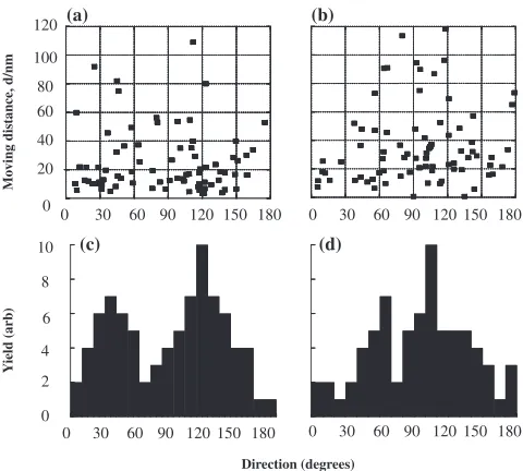
The directions of their motion appeared to be anisotropic, as shown in Fig. 6. The mobility of defects in this figure was taken in the first few minutes under ion irradiation. The two peaks observed in this figure correspond to the projections of 110 directions. Occasionally, three peaks of 110 projections
were observed probably due to the orientation relationship with the surface, which works as strong sink for point defects. In the case of the {001} sample, two peaks were observed along 110 projections at an angle of 90 degrees. The same phenomena were observed throughout the experiments in this work. Figure 7 shows the time dependence of the defect motion. It should be noted that a time bin is set for analysis. It is evident that the moving distance decreases with an increase in the irradiation fluence, and the distributions of Kr2þ and Fig. 5 Mobility of glissile defects in gold under irradiation with 600 keV Ar2þion (1:31011ions/cm2s) at 723 K. The sequence is
captured from videotapes with a time resolution is 1/30 s. Onset of motion and rest position are shown with arrows in (b) and (h), and (c) and (i), respectively. The short lifetime of defects formed through glissile-to-sessile transition is indicated with arrows in (g) and (k).
Direction (degrees)
Y
ield (arb)
Mo
ving distance, d/nm
30 60 90 120 150 180
0 0 30 60 90 120 150 180
30 60 90 120 150 180
0 0 30 60 90 120 150 180 120
60
0 40 100
80
20
10
8
4 6
0 2
a
(a) (b)
(c) (d)
Fig. 6 Distribution of moving distance in {011} gold irradiated with 600 keV Kr2þion flux of5:11011ions/cm2s at temperatures of 723 K in
[image:5.595.57.541.69.324.2] [image:5.595.307.547.397.613.2]Cuþare identical. The formation rate of the mobile clusters
was observed to be dependent on fluence. The highest formation rates coincided with 31014 Cu/cm2 and1:5
1013 Kr/cm2, respectively, and the underlying mechanism is yet to be determined. We suspect that the size of defect clusters plays an important role in their kinetics.
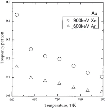
The formation rate of the mobile defects as a function of irradiation temperature, ion species and ion flux is inves-tigated as shown in Figs. 8 and 9. The high formation rate for heavy ion irradiations and a monotonous decrease in the formation within the investigated temperature can be clearly seen in Fig. 8. This phenomenon can be described in terms of subcascades, as employed in the discussion in Fig. 4. Simply applying the TRIM, the probability of 20-keV subcascade formation is 12 and 2 for Xe and Ar, respectively in the investigated thickness. However, according to the exper-imental results as shown in Fig. 8, the ratio of the formation probability of glissile clusters for Xe against Ar is approx-imately 2.5 to 4 depending on the temperatures. The result strongly suggests elimination of the glissile clusters among densely distributed subcascades within the investigated conditions. The result of this model is consistent with the
MD simulation results wherein the bundled crowdions are formed at the periphery of the displacement cascades.16)At
present, additional data is not available with us to discuss this model; therefore, further investigation is required. Figure 9 shows the probability of sessile-to-glissile transition per ion (p) plotted against the ion flux (). A slightly nonlinear (p/1:4) relationship in the case of Cuþ ion irradiation is
evident. The linearity is generally interpreted that a short lifetime object transforms into the other by an impact, and the deviation from it deduces reactions among individual objects and impacts.29) The results indicate that the pre-existing
sessile clusters transform into glissile ones by displacement cascades, and that the transition and the mobility is enhanced by the inter-cascade reaction,29)presumably through energy
[image:6.595.66.278.69.227.2]or momentum transfer. Another expected factor on the non-linearity is the change in stability of the interstitial-type defect clusters influenced by evolution of defects as shown in Fig. 7.
A model for the observed phenomena is proposed as follows.19)Glissile defects, presumed to be consisting of a bundle of crowdions, are formed during the displacement cascade process. Due to the low activation energy for the crowdion bundle motion,17) a large diffusion length in micrometers can be expected in 1/30 s even at low temper-atures. It should be noted that this estimate is invalid for materials that are maintained at high temperatures or under irradiation, where high concentration of point defects, small defect clusters, impurities, and even the fluctuation of atomic arrangement are introduced. Such pre-existing defects or lattice disorders work as the diffusion obstacles, enabling the glissile-to-sessile transition. The diffusion distance depends on the irradiation time and implantation fluence, which directly relates to the lattice defect concentration. Continuous irradiation allows subsequent ion impacts introducing the inverse reaction, i.e., sessile-to-glissile transition, which is affected by energy density of cascades, damage rate and defect stability. According to the MD simulations,19) the sessile-to-glissile transition requires approximately 27 meV in the absence of a potential barrier.
Fig. 7 Distribution of moving distance as a function of irradiation time in gold irradiated with 600 keV Kr2þand 300 keV Cuþions at 723 K.
Fig. 8 Frequency of sessile-to-glissile transition per ion as a function of irradiation temperature and projectile.
1.E-05 1.E-04 1.E-03 1.E-02 1.E-01
1.E+14 1.E+15 1.E+16 1.E+17 Ion Flux,
Frequenc
y per ion
φ/ ions cm-2s-1
[image:6.595.356.497.74.266.2] [image:6.595.83.254.290.465.2]Future prospects for the effects will be to disclose the interactions between glissile defects and various kinds of defects and their agglomerations. In particular, in low-dose-rate environments, such as nuclear reactor vessels and fusion reactor components except for first wall, the glissile defects diffuse in long range without showing any interactions with the obstacles. These defects may accumulate at the grain boundaries and precipitate surface resulting in deterioration of the mechanical strength. These effects can be investigated by MD simulations and other techniques, as well as by cross-sectional TEM observations. An ideal simulation can be performed with the materials such as copper, gold,30) and coherent precipitates,31) along with an application of point defect kinetics under electron irradiations32) and under displacement cascade conditions.33)
4. Conclusions
Defect clusters corresponding to displacement cascades were observed by in-situ TEM observations in copper and gold under irradiations of 100-keV Cþ, 240-keV Cuþ,
600-keV Kr2þ, and 900-keV Xe3þ ions at temperatures ranging
from 573 to 823 K. In addition to the single contrast features associated with the cascades, the multi-contrast features arising from subcascades and glissile defects were observed. The characteristic behaviors of glissile defects are their anisotropic distributions, fluence-dependent distance, ion-mass-dependence, and relatively short lifetime (less than several thirtieths of a second) compared with the vacancy loops and SFTs. In addition to the cascade-driven glissile defects, sessile defects were also transformed into glissile ones under irradiations with ions. This behavior is charac-terized by a one-dimensional back-and-forth motion and spontaneous long range diffusion. These observations sug-gest that the sessile-to-glissile transition and the diffusion along the crowdion directions as well as glissile-to-sessile transition through interaction with certain diffusion obstacles are invisible during microscopy. Inter-subcascade and inter-cascade events were observed at higher formation rates of glissile defects for heavy ion irradiations and as non-linear relationships between the formation rate and ion flux.
Acknowledgements
One of authors (HA) is grateful to Drs. S. J. Zinkle and R. E. Stoller of the Oak Ridge National Laboratory, USA, for their enthusiastic interest in the work and numerous dis-cussions.
REFERENCES
1) T. Diaz de la Rubia and M. W. Guinan: J. Nucl. Mater.174(1990) 151– 157.
2) R. S. Averback, H. Hsieh, T. Diaz de la Rubia and R. Benedek: J. Nucl. Mater.179–181(1991) 87–93.
3) A. Taylor, C. W. Allen and E. A. Ryan: Nucl. Instrum. MethodsB24/ 25(1987) 598–602.
4) C. Kinoshita, H. Abe, K. Fukumoto, K. Nakai and K. Shinohara: Ultramicroscopy39(1991) 205.
5) H. Abe, H. Naramoto, K. Hojou and S. Furuno: JAERI-Research 96-047.
6) H. Sakaida, N. Sekimura and S. Ishino: J. Nucl. Mater.179–181(1991) 928–930.
7) K. Fukumoto, C. Kinoshita, H. Abe, K. Shinohara and M. Kutsuwada: J. Nucl. Mater.179–181(1991) 935–938.
8) S. Ishino, N. Sekimura, H. Sakaida and Y. Kanzaki: Mater. Sci. Forum
97–99(1992) 165–182.
9) I. M. Robertson, J. S. Vetrano, M. A. Kirk and M. L. Jenkins: Philos. Mag.A63(1991) 299–318.
10) S. Ishino, N. Sekimura, K. Hirooka and T. Muroga: J. Nucl. Mater.
141–143(1986) 776–780.
11) S. Ishino, N. Sekimura and T. Muroga: Mater. Sci. Forum15–18(1987) 1105–1110.
12) H. Abe, C. Kinoshita and K. Nakai: J. Nucl. Mater.179–181(1991) 917–920.
13) L. M. Howe and M. H. Rainville: Nucl. Instrum. MethodsB19/20 (1987) 61–66.
14) M. Kiritani: J. Nucl. Mater.251(1997) 237–251.
15) K. Arakawa, S. Arai, H. Orihara, K. Ono and M. Kiritani: J. Electron Microscopy51(2002) S225–S229.
16) R. E. Stoller, G. R. Odette and B. D. Wirth: J. Nucl. Mater.251(1997) 49–60.
17) Yu. N. Osetsky, D. J. Bacon, A. Serra, B. N. Singh and S. I. Golubov: J. Nucl. Mater.276(2000) 65–77.
18) Yu. N. Osetsky, D. J. Bacon, A. Serra, B. N. Singh and S. I. Golubov: Philos. Mag.83(2003) 61–91.
19) H. Abe, N. Sekimura and Y. Yang: J. Nucl. Mater.323(2003) 220–228. 20) K. Niwase: private communication.
21) K. Niwase and H. Abe: Mater. Trans.43(2002) 646–649.
22) H. Abe, H. Naramoto, A. Iwase and C. Kinoshita: Nucl. Instrum. MethodsB127–128(1997) 681–684.
23) J. F. Ziegler, J. P. Biersack and U. Littmark:The Stopping and Range of Ions in Solids, (Pergamon Press, New York, 1985).
24) M. L. Jenkins and M. A. Kirk:Characterization of Radiation Damage by Transmission Electron Microscopy, (Inst. of Physics Publ., 2001) p. 11.
25) M. L. Jenkins and M. A. Kirk:Characterization of Radiation Damage by Transmission Electron Microscopy, (Inst. of Physics Publ., 2001) p. 115.
26) R. S. Walker and D. A. Thompson: Rad. Eff.37(1978) 113–120. 27) N. Sekimura: private communication.
28) L. E. Rehn and P. R. Okamoto: Nucl. Instrum. Methods, Phys. Res.B39 (1989) 104–113.
29) H. Abe: Dr. Eng. Thesis, Kyushu University (1993).