Effects of Solidi
fi
cation Behavior during Filling on Surface Defects
of Aluminum Alloy Die Casting
+Yasushi Iwata, Shuxin Dong, Yoshio Sugiyama and Hiroaki Iwahori
Toyota Central R&D Labs., Inc., Nagakute 480-1192, Japan
Die castings are prone to contain considerable porosities due to the entrapment of air or gases in the molten metal during moldfilling. Reducing the diefilling velocity is effective for reducing the entrapment, but it increases surface defects, such as surface folds and cold shut on die castings.
In this research, the solidification behavior of molten metal during mold filling was investigated by developing a highly sensitive thermosensor with a response time of 0.015 s that can correctly measure the temperature offlowing molten metal. The criterion for the formation of surface defects was further examined based on the solidification behavior of molten metal during moldfilling.
It was found that the type of surface defects varies with the solidification manner of aluminum alloys. Surface fold defects occur on die castings made of JIS AD12.1 alloy with skin-formation type solidification. The occurrence of surface folds can be predicted by the thickness of the solidified layer of the molten metal from the surface of cavity. The critical thickness for the formation of surface folds increases with increasing casting pressure. On the other hand, cold shut defects occur on die castings made of JIS AC4C alloy with mushy-formation type solidification. The molten metal temperature drops toward the tip of the molten metalflow. The occurrence of cold shut defects can be estimated by the temperature of this molten metalflow tip at the time thisflow converges with otherflows. [doi:10.2320/matertrans.F-M2013819]
(Received April 16, 2013; Accepted July 3, 2013; Published August 23, 2013)
Keywords: alloy, aluminum, die casting, defects, surface folds, cold shut, solidification
1. Introduction
Die casting is being applied to the manufacturing process of an increasing number of components owing to the distinguished productivity for castings of intricate shapes. However, metallic molds used for die casting are severely damaged by heavy thermal loads associated with the injection of molten metal at high temperature and high pressure (up to 70 MPa). A strong clamping force for the mold is required in order to handle such high casting pressures. As such, large die casting machines are required for large die castings, which increases production costs. Therefore, if defects that arise from decreases in casting pressure are be controlled, decreasing the die casting pressure will be an effective method of reducing production costs.15)
At the same time, gas porosities generally occur in die castings from the entrapment of air and gases into the molten metal due to violent flow during high-velocity injection.68) Extending the low-velocity injection time has been reported to be an effective method of reducing the amount of entrapped gases and air.6,8) However, a large temperature
drop in the molten metal due to a long injection time gives rise to other defects, such as surface folds, cold shut, even misrun.9,10)Therefore, it is necessary to clarify the causes and
conditions of surface defects in order to perform die casting under optimal conditions.
Aluminum alloy die castings for silicon content lower than that of JIS AD12.1 aluminum alloy (referred to hereinafter as AD12.1 alloy) is also required due to the diversification of needs with respect to the properties of die casts. The solidification type changes as the content of silicon decreases, and this change may affect the castability of the alloys.
In the present study, focusing on the solidification behaviors of molten metal in the mold during injection, the
surface qualities of die castings were examined in relation to the temperature of the molten metal in the mold and the solidification type of alloys of different silicon contents under various injection conditions.
2. Experimental Method
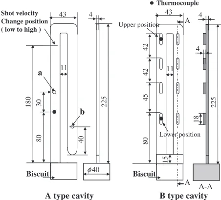
Schematic diagrams of the experimental die castings are shown in Fig. 1. Two types of die castings were used in the present study. One is a¥-shaped die casting having a width of 16 mm, a thickness of 4 mm and a length of 460 mm, as shown in Fig. 1(A), and the other die cast is a reverse U-shaped die casting, both sides of which are connected to the biscuit, as shown in Fig. 1(B). Die casting experiments were performed using a mold of each type of die casting mounted to a vertical injection die casting machine.
Thermocouple
225
4 43
11
80
180
43
11
80
42
45
42
225
4
4
18
A
A A-A
15
Biscuit Biscuit
A type cavity B type cavity
φ40
Shot velocity Change position ( low to high )
30
40
a
b
Upper position
Lower position
Fig. 1 Shapes of experimental castings.
+This Paper was Originally Published in Japanese in J. JFS. 85(2013)
914.
[image:1.595.313.539.565.770.2]AD12.1 alloy and JIS.AC4C aluminum alloy (referred to hereinafter as AC4C alloy) were used for the type A experimental die casting. The compositions of AD12.1 alloy and AC4C alloy are Al11 mass%Si2.34 mass%Cu 1.2 mass%Mg and Al7 mass%Si0.3 mass%Mg, respec-tively, and the liquidus temperatures are 837 and 883 K, respectively. Molten metal was poured into a sleeve that was thermally insulated by Kaowool sheet (a sheet of ceramic fibers made by Isolite Insulating Products Co., Ltd.) linings and wasfirst injected into the cavity by two-step injection at a low velocity of 0.03 m·s¹1followed by a high velocity of 0.7 m·s¹1. The injection was shifted from the low-velocity
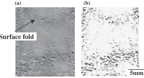
step to the high-velocity step when the tip of the flowing molten metal reached a point 180 mm from the top surface of the biscuit. Die casting experiments were performed under casting pressures ranged from 30 to 65 MPa and injection temperatures of the molten metal ranging from 883 to 999 K. The injection temperature of the molten metal was estimated based on the initial temperature, the cooling curve in the sleeve of the molten metal and the injection time. The temperature of the molten metal during mold filling was measured using a thermocouple installed in the cavity at a point of 80 mm from the top surface of the biscuit. Surface fold defects11)were observed in some of the die castings, as shown in Fig. 2(a). The surface fold defects were quantita-tively assessed according to the area of the dented surface of the die casting, which was measured from the binary image of the surface, as shown in Fig. 2(b). The micro- and the macro-structures of the low-velocity and the high-velocity filled portions were examined by cutting the die casting at positions a and b shown in Fig. 1(A).
The type B experimental die casting was made of AC4C alloy at injection temperatures ranging from 963 to 1,003 K. The temperatures of the molten metal in the cavity during mold filling were monitored using thermocouples installed at the positions shown in Fig. 1(B). The displacement of the plunger was measured based on the electrical resistance variation of a potentiometer fixed to the injection cylinder. The defects, such as surface folds, cold shuts and misrun, were assessed according to the appearance of the upper part of the die casting, which corresponds to the meeting point of the molten metalflows in the experimental die casting.
The temperature measurements of the present study were conducted using a detachable quick-response thermo-sensor,12)which consisted of a ¤0.1-mm C.A. type
thermo-couple protected by a ceramic insulator. The thermo-sensor was installed in the mold such that its tip was positioned at the center of the cavity in the thickness direction. In order to confirm the sensitivity of the thermo-sensor, temperature measurements were also conducted using an undetachable type used in previous studies8,9) and a ¤0.3-mm C.A. type thermocouple and the obtained results were compared to those obtained using the thermo-sensor.
3. Experimental Results and Discussion
3.1 Sensitivity of the quick-response thermo-sensor
The cooling curve of the experimental die casting A as pure aluminum was injected into the cavity at the melting point of 933 K and a casting pressure of 65 MPa is shown in Fig. 3. The temperature measured by the stationary thermo-sensor began to increase 0.02 s after the start of moldfilling and reached a peak temperature of 868 K in 0.1 s. While the temperature of the detachable thermo-sensor began to rise as soon as the molten aluminum was injected into the cavity and reached a peak temperature of 933 K. The time for reaching the peak temperature varied with the diameter of the thermocouple wires and was 0.03 s for the thermocouple with¤0.3-mm wires and 0.015 s for the thermocouple with¤ 0.1-mm wires. That is to say, the detachable thermo-sensor consisting of ¤0.1-mm wires can measure the molten metal temperature with a response time of 0.015 s.
3.2 Solidification behavior of molten metals during mold
filling and the surfaces of die castings
AD12.1 alloy die castings made with different injection temperatures of molten metal are shown in Fig. 4. The cavity was completely filled with AD12.1 alloy, even when the injection temperature of the molten metal was decreased to 883 K (with a superheat of 46 K from the liquidus temperature). However, for such a low injection temperature of molten metal, surface fold defects were observed on the surface of the low-velocity filled portion of the die casting, as indicated by the arrows in Fig. 4. The surface fold defects were prevented by increasing the injection temperature of
(b)
5mm
Surface fold
(a)
Fig. 2 Appearances of castings with surface folds, (a) image of surface, (b) binary image of surface.
0
0.05 0.1
0.15
0.2
0.25
Time from shot,
t
/s
270
470
670
870
T
emperatur
e.
T
/K
Stationary type thermocouple
Replaceable thermocouple
φ=0.1mm
φ=0.3mm
[image:2.595.51.289.71.201.2] [image:2.595.321.529.71.262.2]the molten metal to 943 K (with a superheat of 106 K based on the liquidus temperature).
The mold filling behavior of AC4C alloy (Fig. 5) was found to have the following features. The molten metal filled only 50 mm of the cavity for an injection temperature of 923 K (superheat: 40 K). Although thefilling length in the cavity increased with the increase in the superheat of the molten metal, a superheat of 60 K (molten metal temperature: 943 K) was still not sufficient for the metal to completely fill the entire cavity. The cavity was eventually filled completely with the molten metal of a superheat of 70 K. Unlike AD12.1 alloy, no surface fold defects were observed on the surface of AC4C alloy die castings, even the incompletelyfilled die castings. In other words, for the same superheat of molten metal, the occurrence of surface defects such as surface folds, misrun, etc., differ greatly for different alloy die castings.
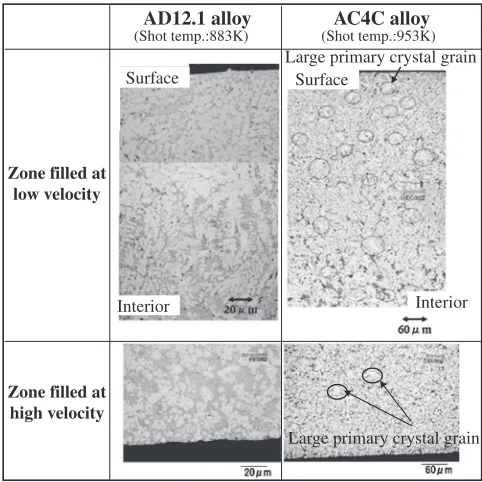
The micro structures of the cross sections of low-velocity injection (Figs. 1-A, a) and high-low-velocity injection (Figs. 1-A, b) portions of die castings of different alloys are shown in Fig. 6. For AD12.1 alloy, the cross section of the low-velocity injection portion was observed to have a structure consisting of two layers, i.e., dendrites of primary aluminum crystals with large secondary arm spacing in the area just beneath the surface and dendrites with compara-tively small secondary arm spacing in the internal area. In
contrast, only single-layer structures were observed in the high-velocity injection portion. The cross section of AC4C alloy die castings features a gradual enlargement of the crystal grains of primary aluminum from the surface to the center with a dispersion of a few large grains.
The molten metal temperatures in the cavity, as shown in Fig. 1-A, during mold filling are shown in Fig. 7 (the moment at which the plunger was started was taken as the start time) for AD12.1 and AC4C alloys for a casting pressure of 30 MPa. For AD12.1 alloy injected at 883 K, the molten metal temperature was kept at 831 K during the low-velocity injection stage, but increased to 852 K, which is higher than the liquidus temperature, as the injection velocity shifted to the high-velocity injection stage. For AC4C alloy, which was injected at 953 K, the molten metal cooled gradually during low-velocity injection. Although the temperature of the molten metal exhibited a small increase after the injection was shifted to the high-velocity injection stage, the temperature of the molten metal never reached the liquidus temperature of AC4C alloy.
The difference between the structures of AD12.1 and AC4C alloy die castings will be discussed based on the temperature changes of molten metals in the cavity during mold filling as illustrated above. AD12.1 is a typical alloy that undergoes skin-formation solidification in the cooling process. Although the temperature of molten metal initially decreased during low-velocity injection, there was no further decrease in temperature when the molten metal began to solidify due to the latent heat brought about by the AlSi eutectic solidification. Therefore, a solid layer is considered to form on the surface of the cavity during flowing due to its skin-formation solidification feature. When the injection shifted to the high-velocity stage, subsequently injected hot molten metal flowed into the inside of the solid layer that had formed on the surface of the cavity during the low-velocity injection stage. At the end of mold filling, the
Shot temp. ,T/K
883 913 943
5mm
30MPa
Measured area
Surface fold
Fig. 4 Appearances of AD12.1 alloy castings under different casting conditions.
10mm
10mm
10mm 5mm
953 943 923
Shot temp.
T
/K
Fig. 5 Appearances of AC4C alloy castings under different casting conditions.
Surface
Interior Interior
Large primary crystal grain
Large primary crystal grain Surface
AD12.1 alloy AC4C alloy
Zone filled at high velocity Zone filled at
low velocity
(Shot temp.:883K) (Shot temp.:953K)
[image:3.595.306.547.70.311.2] [image:3.595.55.285.72.243.2] [image:3.595.54.283.301.431.2]pressure in the cavity began to increase and pushed against the solid surface layer, strengthening the contact with the surface of the cavity and promoting thermal conductance between the solid layer and the surface of the cavity. As a result, the molten metal inside the solid layer was rapidly cooled and formedfine primary aluminum crystals with small secondary dendrite arm spacing. At the low-velocity injection stage, the thermal conductance between the solid layer and the cavity surface was comparatively weak, thus coarse primary aluminum crystals were considered to form.
In the case of AC4C alloy, the structures of the die castings forming in both the low- and the high-injection velocity stages contained the same coarse primary aluminum crystals. AC4C alloy is a typical alloy exhibiting the mushy solidification feature. In AC4C alloy, the amount of primary aluminum crystals increases in proportion to the temperature decrease of molten metal from the liquidus temperature. Therefore, the primary aluminum crystals in the flowing molten metal increased with the decrease in temperature and the mold was filled with molten metal in the mushy state. The above-described behaviors of the molten metal of AC4C alloy are the same for the low- and the high-velocity injection processes. The observed mixing structures of large and small primary aluminum crystals in the AC4C alloy die castings are assumed to be formed by solidifying the large and small primary crystals during and after mold filling, respectively.
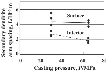
The secondary dendrite arm spacings in the area near the surface and at the center in the thickness direction in the low-velocity portion of AD12.1 alloy die castings are shown in Fig. 8. The secondary dendrite arm spacing is inde-pendent of the casting pressure in the area near the surface, but decreases with the increase in casting pressure at the center in the thickness direction. In other words, as mentioned above, the solid surface layer formed during the low-velocity injection stage was not affected by the pressure exerted at the end of mold filling, whereas the solidification of the inner molten metal thatflowed in after the shift of the injection velocity was influenced by the casting pressure. Thus, the secondary dendrite arm spacing decreased with
the increase in the casting pressure due to the more rapid cooling.
The secondary dendrite arm spacings of the coarse and fine primary aluminum crystals in the cross sections of low-and high-velocity injection portions of AC4C alloy die castings are shown in Fig. 9. The coarse primary aluminum crystals can be observed in both the low- and the high-velocity injection portions, and the secondary dendrite arm spacings are approximately the same. The secondary arm spacings of the fine primary aluminum crystals increase toward the center of the cross section, and this tendency is the same for both the low- and the high-velocity injection Shot temp. 883K
270 470 670 870
0 0.5 1.0 1.5
0 20 40 60
Time ,
t
/s
T
emperatur
e ,
T
/K
Displacement ,
L
/mm
Pr
essur
e ,
P
/MP
a
Liquidus line:837K
Molten metal
temp. Plunger
displ.
Plunger press.
(a) (b)
Plunger press. Plunger
displ. Molten
metal temp. Liquidus line 883K
0 20 40 60
0 0.5 1.0 1.5 470
670 870
T
emperatur
e ,
T
/K
Time ,
t
/s
Displacement ,
L
/mm
Pr
essur
e ,
P
/MP
a
Shot temp. 953K
270
Fig. 7 Cooling curves of castings, (a) AD12.1 alloy, (b) AC4C alloy.
Surface
0 20 40 60 80
0 2 4 6
Casting pressure, P/MPa
Secondary dendrite arm spacing,
L
/10
-6
m
Interior
Fig. 8 Dependence of secondary dendrite arm spacing on casting pressure (AD12.1 alloy).
Coarse primary crystal
Fine primary crystal Fast shot zone Slow shot zone
Fast shot zone Slow shot zone
Coarse primary crystal
Fine primary crystal
0 1 2 3 4
0 4 8
(Surface) (Center) (Surface)
Position in thickness direction, L/mm Secondary dendrite arm spacing,
L
/10
-6 m
[image:4.595.136.459.70.261.2] [image:4.595.335.517.312.436.2] [image:4.595.312.540.490.592.2]portions. This result supports the assumption that the molten metal is strongly cooled due to the start of the pressure increase at the end of mold filling. In other words, unlike AD12.1 alloy, in which high-velocity molten metal flows into the cavity inside the low-velocity molten metal, in the case of AC4C alloy, the subsequently injected molten metal containing primary aluminum crystals pushes the molten metal injected during the low-velocity injection stage, and the metalsflow together.
In order to confirm the above assumption, the plunger was withdrawn during the process of the low-velocity injection, and the structure of the die casting was investigated. The appearance and the cross section of the die casting are shown in Fig. 10. A hollow cross section appears in the low-velocity injection portion of the AD12.1 alloy die casting. This hollow cross section is considered to form as the molten metal flows out, leaving a solid surface layer when the plunger is withdrawn. However, in the case of AC4C alloy, such a hollow cross section was not observed, and no molten metal flowed out. That is to say, the molten metal in the cavity did not have sufficient fluidity to flow out and thus remained in the cavity and solidified after the plunger was withdrawn because of the mushy solidification of the AC4C alloy. Therefore, the difference of the structures in the cross sections of AD12.1 and AC4C alloy die castings can be contributed to the differences in skin solidification and mushy solidification, which occur around eutectic com-positions and in the area of hypoeutectic comcom-positions, respectively.
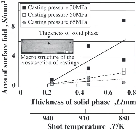
The relationship between the area of surface fold defects and the thickness of the solid surface layer is illustrated in Fig. 11 for AD12.1 alloy die castings. The macro-structure of the low-velocity injection portion (injection temperature: 913 K, casting pressure: 50 MPa) near the thermo-sensor and the position for measuring the thickness of the solid layer are also given in Fig. 11. The solid surface layer that forms during the low-velocity injection becomes thicker as the injection temperature of the molten metal decreases, and the area of the surface fold defects increases with the increase in the thickness of the solid surface layer. For the same thickness of the solid surface layer, the area of the surface fold defects decreases with the increase in the casting pressure. In other words, the surface fold defects of AD12.1 alloy die castings are considered to form during the solidification of the solid surface layer during the low-velocity injection stage and do not occur if the solid surface layer is thinner than 0.2 mm. If the thickness of the solid surface layer is greater than 0.2 mm, it is necessary to increase the casting pressure so as to prevent surface fold defects.
3.3 Temperature of the flowing molten metal in the cavity and the cold shut defect
The above experiments revealed that the alloy formed by mushy solidification tended to have a short flow length and was prone to cold shut defects in die castings. In order to clarify the formation of cold shut defects, AC4C alloy was cast by using the mold shown in Fig. 1-B under various conditions. Specifically, the appearances of the die castings were inspected and compared with the molten metal temperatures at the merging point of the cavity.
The molten metal temperature, casting pressure and plunger displacement are shown in Fig. 12 for the case in which AC4C alloy was cast with a molten metal temperature of 963 K, an injection velocity of 0.26 m·s¹1 and a casting pressure of 65 MPa, where the start time is defined as the time at which the mold closing isfinished. The plunger began to move at 0.064 s, and the molten metal reached the thermo-sensor installed in the lower region of the cavity (hereinafter referred to as the lower thermo-sensor) at 0.088 s. The lower region thermo-sensor exhibited a peak temperature of 904 K
Cross-section
Cross-section
AD12.1
alloy
AC4C
alloy
Vacancy
Appearance Appearance
[image:5.595.48.290.68.152.2]10mm
Fig. 10 Appearances of castings with depressurization infilling process.
Casting pressure:30MPa Casting pressure:50MPa Casting pressure:65MPa
Ar
ea of surface f
old ,
S
/mm
2
0
0.2
0.4
0.6
Thickness of solid phase ,
L
/mm
0.8
0
4
8
Macro structure of the cross section of castings
Thickness of solid phase
940
910
880
[image:5.595.313.540.70.287.2]Shot temperature ,
T
/K
1mmFig. 11 Dependence of surface folds of AD12.1 alloy castings on the thickness of solid phase.
270 470 670 870
T
emperatur
e ,
T
/K
Displacement ,
L
/mm
0 0.1 0.2 0.3 0.4 0.5
20 40 60
0
Pr
essur
e ,
P
/MP
a
Time, t/s
Molten metal Temp.
Upper position
Lower position
Plunger press.
[image:5.595.321.532.348.494.2]Plunger displ.
at the time of 0.01 s after touching the molten metal. The molten metal reached the thermo-sensor installed in the upper region of the cavity (hereinafter referred to as the upper thermo-sensor) at 0.1 s, and the upper thermo-sensor exhibited a peak temperature of 867 K at the time of 0.02 s after touching the molten metal. The plunger eventually stopped moving at 0.13 s. The temperature of the lower thermo-sensor was always higher than that of the upper thermo-sensor during mold filling, i.e., molten metal of a higher temperature than that of the upper region continued to flow through the lower region of the cavity during the mold filling. Each thermo-sensor had a response time of 0.015 s and exhibited a peak temperature within 0.02 s after touching the molten metal.
By defining the temperature indicated by the thermo-sensor at the time of 0.2 s after touching the molten metal as the temperature of the tip of the molten metal, we calculated the temperature of the molten metal uponfirst arriving at the center of the apex of the cavity. Specifically, we extrapolated the tip temperature based on the relationship between the filling fraction of the cavity and the flowing distance of the molten metal. Figure 13 illustrates the temperature decrease of the tip of flowing molten metal injected under various casting conditions. The temperature of the molten metal upon arriving at the center of the apex of the cavity is estimated to fall to as low as 803 K under an injection temperature of 993 K and an injection velocity of 0.20 m·s¹1. When the
injection velocity was increased to 0.26 m·s¹1, the molten
metal temperatures at the moment of reaching the center of the apex were estimated to be 840 and 863 K for injection temperatures of 963 and 993 K, respectively, i.e., the temperature decrease was not so large. Comparing the above-estimated temperatures of the tip of the molten metal at the merging point revealed that the temperature drop of the molten metal in the cavity was more significantly affected by the injection velocity than the injection temperature of the molten metal.
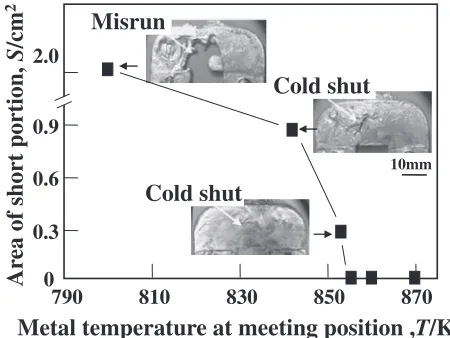
The investigation results for surface fold and cold shut defects of AC4C alloy die castings are shown in Fig. 14, together with the temperature of the molten metal at the merging point when varying the injection velocity and injection temperature of the molten metal. The defects were
quantified by measuring the areas of the dented portions on the surfaces of die castings. Photographs of appearances near the merging point of the die castings (apex of the cavity) are also shown in Fig. 14. For the case in which the molten metal temperature is estimated to be 803 K upon merging at the center of the apex of the cavity, the apex of the cavity is not fullyfilled and the die casting has a misrun defect. The above result can be easily explained by considering the fact that the temperature of 803 K is below the liquidus temperature of AC4C alloy. Therefore, the estimated temperature of the molten metal uponfirst arriving at the center of the apex of the cavity can be considered to be a reasonable value. For the case in which the molten metal temperature is estimated to be 843 K upon merging at the center of the apex of the cavity, although the apex of the cavity is almost fully filled, the molten metals do not adhere to each other and an obvious cold shut is left on the die casting. When the tip temperature of the molten metal on merging is as high as 858 K, molten metals adhere well to each other and only a minor cold shut is observed. Thus, the extent of the cold shut can be considered to depend on the tip temperature of the molten metal when merging at the center of the apex of the cavity. It can be concluded that if the tip temperature of the molten metal when merging at the center of the apex is higher than 858 K, no surface defects will occur. If the tip temperature decreases to a value lower than 858 K, cold shut defects will begin to occur and will deteriorate as the tip temper-ature decreases further.
4. Conclusions
Surface fold and cold shut defects of die castings were investigated with respect to the temperature of molten metal during moldfilling through experimental die casting. Based on the results, we present the following conclusions.
(1) For AD12.1 alloy, the molten metal solidifies from the wall of the mold cavity toward the center of the cross section, forming a solid surface layer during mold filling. If the temperature of the molten metal decreased too much, the solid surface layer becomes thicker and
0 4000 8000 12000
770 870 970 1070
Filling volume, V/mm
3T
emperatur
e ,
T
/K
Meeting position Shot temp.
Measured temp. Lower position
Upper position Extrapolation
[image:6.595.313.538.70.239.2]Shot velocity:0.26m/s Shot velocity:0.26m/s Shot velocity:0.20m/s
Fig. 13 Colling behavior of AC4C molten metal halfway throughfilling up.
Metal temperature at meeting position ,
T
/K
790 810 830 850 870
0 0.3 0.6 0.9 2.0
Ar
ea of short portion,
S
/cm
2
Cold shut
Cold shut
Misrun
10mm
[image:6.595.64.277.70.225.2]the contact with the cavity wall weakens, resulting in surface fold defects. The critical thickness of the solid surface layer at which surface fold defects form was found to be 0.2 mm for AD12.1 alloy.
(2) For AC4C alloy, solid phase crystallizes and increases inside the molten metal as the mold filling proceeds, and the cavity isfilled with molten metal in the liquid-solid coexisting state. For alloys formed by mushy solidification, some liquid metal remains in the vicinity of the cavity wall, even at the end of mold filling and the contact between the cavity wall and the surface of the die casting is strengthened by the casting pressure, and thus, no surface fold defects occur.
(3) In the mold filling process of AC4C alloy, the temperature decrease of the molten metal increases with theflow length in the cavity and close to the tip of the molten metalflow. The cold shut defects that occur in alloys formed by mushy solidification depend on the temperature of the molten metal and begin to occur as the tip temperature of the molten metal flow decreases to a low threshold value.
REFERENCES
1) Y. Iwata, S. Dong, Y. Sugiyama and H. Iwahori: JFS83(2011) 421 426.
2) Y. Iwata, S. Dong, Y. Sugiyama and H. Iwahori: Mater. Trans.53
(2012) 483488.
3) S. Tanikawa, K. Asai, Y. Yang, H. Nomura and E. Kato: Rep. JFS Meeting139(2001) p. 134.
4) Y. Sugiyama, H. Iwahori, K. Yonekura and Y. Ookochi: IMONO66 (1994) 412417.
5) N. Nishi, H. Sasaki, T. Hirabara and Y. Takahashi: IMONO60(1988) 777783.
6) Y. Iwata, Y. Yamamoto, M. Nakamura, K. Mizuno and S. Tsuboi: J. Jpn. Inst. Light Met.39(1989) 550554.
7) Y. Iwata, K. Tozawa, Y. Yamamoto, M. Nakamura, K. Mizuno and M. Tsuboi:J. Jpn. Inst. Light Met.37(1987) 4852.
8) Y. Yamamoto, Y. Iwata and M. Nakamura: IMONO60(1988) 770 776.
9) Y. Iwata, K. Tozawa, Y. Yamamoto, M. Nakamura and A. Sasaoka: J. Jpn. Inst. Light Met.36(1986) 1014.
10) Y. Iwata, K. Tozawa, Y. Yamamoto and M. Nakamura: ALUMINIUM 63(1987) 6669.