In
fl
uence of Casting Conditions on Initially Solidi
fi
ed Structures Formed
during Permanent-Mold Casting of Zn
Al and Al
Cu Alloys
Hiroshi Kato
+1and Tsuyoshi Nakahara
+2Course of Mechanical Engineering, Graduate School of Science and Engineering, Saitama University, Saitama 338-8570, Japan
Molten Zn2.54 mass%Al (the Zn2Al) and Al2.35 mass%Cu (the Al2Cu) alloys were poured on the copper chill block to obtain initially solidified structures on the bottom of the specimen. The Zn2Al alloy poured on the chill block polished with emery paper formed discs that protruded about 1 µm from the bottom of the alloy specimen, as the case of the Al2Cu alloy. From the discs, predendrites that forms a cellular structure extended radially, and then dendrites grew outside the predendrites in the preferred orientation. The solute content had a local maximum at the center of the disc, which suggests that the solidification began from undercooled liquid. The orientation of the discs formed on the bottom of the Zn2Al ally specimen was [0 0 0 1] direction, but the discs formed on the bottom of the Al2Cu alloy specimen did not show a specific orientation. With increasing surface roughness of the polished chill block, the disc diameter increased but the areal number density of discs decreased. Furthermore, with increasing pouring temperature, the disc diameter and the areal number density of discs both increased. For a buffed chill block, however, no disc appeared for the Zn2Al alloy specimen butfine dendrites appeared on the bottom. In contrast, large discs formed on the bottom of the Al2Cu alloy. In particular, when the molten Al2Cu alloy was poured at 800°C or higher on the buffed chill block, two types of discs appeared on the bottom: normal discs of 20 to 30 µm in diameter, and very large discs (superdiscs) of 100 to 200 µm in diameter. Following these results, the formation process of the initially solidified structure is discussed. [doi:10.2320/matertrans.M2013160]
(Received April 26, 2013; Accepted August 12, 2013; Published October 4, 2013)
Keywords: casting, permanent mold, solidification structure, chilled layer, zinc alloy, aluminum alloy, disc, predendrite
1. Introduction
Recently, microcasting techniques15)have been developed
to produce microscale systems and devices, such as MEMS (Micro Electro Mechanical Systems). Gross castings consist of the chilled layer, columnar grains and equiaxed grains,6)
and their mechanical properties are largely influenced by the grain size7)and the dendrite arm spacing.8)To the contrary,
the surface layer occupies a considerable part of the microscale castings, and hence the state of the surface layer greatly influences the mechanical properties of the cast product.
Biloni and Chalmers9) observed the initially solidified structures on the bottoms of the AlCu alloy and the PbSn alloy specimens, and found that when the molten alloy was poured on the permanent mold, discs were formed on the surface of the specimen. Then, predendrites extended from the discs radially, and finally dendrites grew in the preferred orientation. They9) also measured the copper content in the
disc of the Al0.6 mass% Cu alloy specimen poured on a copper chill block, and detected a higher copper content, close to the average content in the alloy, at the center of the disc. From this result, they9) supposed that the discs were
formed by a nondiffusional process. In addition, Prates and Biloni10)examined the effect of the casting conditions on the
formation of the discs in AlCu alloy specimens, and found that the disc density monotonically increased with increasing surface roughness of the chill block, in proportion to the square of the heat transfer coefficient. Thereafter, Nishi
et al.1118)carried out a series of studies on the formation of the discs in the AlCu alloys, and confirmed that the disc formation was greatly influenced by heat transfer on the
surface of the chill block. Nishi et al.16) also analyzed the solute content in the discs, and found that the copper content had a local maximum at the center of a disc on the bottom of the Al0.6 mass%Cu alloy poured on the copper chill block, as was observed by Biloni and Chalmers.9)However, they16)
also found that when the alloy was poured on the cast-iron chill block, the solute content had a minimum at the center of the disc and monotonically increased with the distance from the disc center. This means that the formation of the disc is not necessarily a nondiffusional process.
Bower and Flemings19)precisely examined the distribution of orientations of dendrites on the chilled surfaces of the Al 4.5 mass%Cu alloy cast on a permanent mold and concluded that the orientations of the dendrites are random on the chilled surface of the specimen. The same result was obtained by Edmunds20)for aluminum alloy and¡-¢brass diecastings. Edmunds20,21) also reported that a (0 0 0 1) texture was formed on the chilled surface of the zinc die-cast products. From these results, the process of the formation of the initially solidified structure, especially the discs, has been clarified for AlCu alloy castings with the FCC crystal structure. However, there has still been no report on the formation of the discs when alloys of other crystal structures are produced by permanent mold casting. In addition, in the previous works, the molten alloy was poured on chill blocks polished with emery paper. This procedure produces many asperities on the surface of the chill block that can act as nucleation sites of the discs, and thus many discs are formed on the surfaces of the castings. For microscale casting, however, the surface of the permanent mold should be mirror-finished to improve the accuracy of the cast products, and thus sites for formation of the discs are very limited on the surface of the mold. Therefore, to advance the microscale casting techniques, it is important to study the formation of discs when the molten alloy is poured on the mirrorfinished chill block.
+1Corresponding author, E-mail: hkato@mech.saitama-u.ac.jp, hkato@
tbz.t-com.ne.jp, Present address: Emeritus Professor, Saitama University +2Present address: Kawasaki Heavy Industries, Ltd., Kobe 650-8680, Japan
In the present work, molten ZnAl alloy and AlCu alloy were poured on copper chill blocks under different conditions, and the influences of the surface roughness of the chill block and the pouring temperature on formation of the discs were examined. The solute distribution in the discs and the orientation of the disc were also analyzed. Finally, based on these experimental results, the formation process of the initially solidified structure was discussed.
2. Experimental Procedure
2.1 Preparation of the specimen
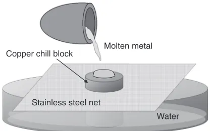
Zn2 mass% Al and Al2 mass% Cu alloys were melted at a temperature of 470 to 600°C and 670 to 800°C, respectively, and then poured on the copper chill block from a height of about 30 mm, as shown in Fig. 1. The masses of obtained alloy nuggets were 20 to 30 g. The chill block was 40 mm in diameter and 100 mm in height, and the upper surface for contact with the molten alloy was polished with emery paper of #60 to #1500, or mirror finished by buffing. During pouring of the molten alloy, the lower end of the chill block was immersed in water. The average surface roughness Ra and the rugosity Rq of the chill block are
summarized in Table 1. The rugosity was slightly higher than the average surface roughness. The chemical analysis with an X-rayfluorescence analyzer found the compositions of the ZnAl and AlCu alloys to be Zn2.54 mass% Al and Al2.35 mass% Cu, respectively. Hereafter these alloys will be referred to as the Zn2Al alloy and the Al2Cu alloy for simplicity.
2.2 Metallography
The bottom of the alloy specimen was observed through an optical microscope, and photographs were taken for measure-ment of the discs. Two or three photographs magnified by about 200©(with an area of 1©1.25 mm2) were taken for each alloy specimen, and the number of discs and their diameters were measured. The minimum measured diameter of a disc was 4.8 µm. The number of discs in the photograph was divided by the measured area to obtain the areal number density of discs. Hereafter, the areal number density of discs will be referred concisely to as the disc number density, and the disc diameter and the disc number density will be collectively referred to as the disc parameters.
After the optical microscope observation, the discs were observed using a scanning electron microscope (SEM) with
an acceleration voltage of 15 kV and a sample current of 50 nA, and using a laser scanning microscope with a 407 nm semiconductor laser.
After the bottom of the specimen was observed, the specimen was sectioned normal to the bottom through the center of the disc, polished and etched for observation through optical microscope and analysis using an electron probe microanalyzer (EPMA).
The solute distribution in the disc was analyzed on the bottom and through the cross section of the alloy specimens using the EPMA with an accelerating voltage of 15 kV and a sample current of 50 nA. The crystal orientation of the discs was also analyzed on the specimen bottom using the micro X-ray diffraction technique with Cu K¡ radiation as the X-ray source, under a tube voltage of 40 kV and a tube current of 30 mA. The X-rays were irradiated at an angle of 30° from the surface of the sample to obtain the diffraction lines. The irradiated area was about 30 µm in width and 60 µm in length and included both the disc and its surrounding area.
3. Experimental Results
3.1 Initially solidified structures
On the bottom of the alloy nugget, the structure was different at each position. Figure 2 shows the interior and the periphery of the Zn2Cu alloy specimen poured on the chill block polished with #60 emery paper. In the interior (Fig. 2(a)), relatively flat surfaces are observed, and there is a shallow dent at the pouring center. Around the dent, seams appear that have been transferred from scratches on the surface of the chill block. At the periphery (Fig. 2(b)), lots of discs are aligned along seams. The bottom structures of the Al2Cu alloy specimen were similar to those of the Zn2Cu alloy specimen. In the permanent casting, molten alloy is poured in a permanent mold through a runner, and hence the surface of castings is not considerably influenced by pouring of molten alloy. Therefore, discussion will be focused on the surface structures in the periphery of the specimen.
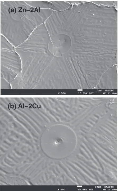
Figure 3 shows SEM micrographs of the discs on the bottom of the alloy specimens poured on the chill block polished with #60 emery paper. At the center of the discs, there was a small dent, which was thought to be a trace of the cusp of the copper chill block. On the Zn2Al alloy specimen, as shown in Fig. 3(a), dendrite arms grew in six directions, which suggests that the bottom of the Zn2Al alloy specimen has (0 0 0 1) plane orientation. The dendrites on the Al2Cu alloy specimen grew in four directions, as shown in Fig. 3(b), which suggests that the bottom of the Al2Cu alloy specimen has (0 0 1) plane orientation.
Molten metal
Stainless steel net
Water Copper chill block
[image:2.595.65.273.69.199.2]Fig. 1 Setup for pouring of molten alloys on the copper chill block.
Table 1 Average surface roughness and rugosity on the surface of polished or buffed chill blocks.
(/µm) Emery paper
Buff
#60 #100 #240 #500 #1500
Ra 4.36 2.47 1.26 0.39 0.19 0.04
However, in the Al2Cu alloy specimen, there were multiple non-identical directions.
Images of the disc obtained with the laser microscope are shown in Fig. 4. In thisfigure, the discs were protruded about 1.7 and 0.5 µm from the bottom of the Zn2Al alloy and the Al2Cu alloy, respectively. In addition, the dendrites growing on the bottoms had grooves of 0.1 to 0.2 µm in depth. From these observations, it was found that the discs caused protrusions of about 1 µm on the surface of cast products.
Cross sections normal to the bottom of the specimen are shown in Fig. 5. As shown in Figs. 5(a) and 5(c), when the molten alloy was poured on the chill block polished with#60 emery paper, the discs grew semispherically on the specimen bottom and the predendrite extended radially from the discs. On the bottom of the alloy specimen, apart from the discs, there was a thin surface layer, from which a rod-like or dendritic structure grew. When the molten alloy was poured on the buffed chill block, as shown in Figs. 5(b) and 5(d), there was a thin surface layer on the specimen bottom, and the rod-like or dendritic structure grew on the bottom, as well. In Fig. 5(d), the structure growing from the surface layer was not specified, but in comparison with the structures observed in other areas, it was thought that the dendritic structure grew from the surface layer.
From observations of the bottoms and the cross sections of the specimens, it was found that the surface layer consisted of dendrites growing on the bottom of the specimen.
3.2 Influence of casting conditions on the formation of
discs
Figure 6 shows the changes in the disc parameters with distance from the pouring center on the bottom of the Zn 2Al alloy specimen poured on the chill block polished with #60 emery paper. In the figure, the error bars for the disc diameter indicate the standard deviation. The disc diameter increased with the distance from the pouring center, and took a constant value of 20 to 25 µm at a position more than 10 mm from the pouring center. The disc number density also increased with the distance from the pouring center, and took a constant value of about 20 mm¹2 at a position more than
10 mm from the pouring center. The disc parameters of the Al2Cu alloy specimen showed the same tendency as those of Zn2Al alloy specimen. Thus, from these results, it was found that the disc parameters took constant values at a distance more than 10 mm from the pouring center. Therefore the disc parameters were measured in this region, and the influence of the casting conditions on the disc parameters is discussed below.
The changes in the disc parameters with increasing surface roughness of the chill block are shown in Fig. 7. In both alloys, at a rugosity of 0.54 µm or larger, the disc diameter increased with increasing rugosity, but the disc number density decreased. These results are consistent with those
(a)
300
μμ
m
(b)
100
μ
m
Fig. 2 Bottom structures in the interior (a) and at the periphery (b) of the Zn2Al alloy specimen poured at 550°C on the chill block polished with
#60 emery paper.
(a) Zn–2Al
(b) Al–2Cu
[image:3.595.316.539.69.430.2] [image:3.595.59.280.71.408.2]of Prates and Biloni.10) In the Zn2Al alloy specimen,
however, no discs were observed at a rugosity of 0.27 µm or smaller. Figure 8 shows the changes in the disc parameters with pouring temperature. In both alloys, with increasing pouring temperature, the disc parameters increased, which is consistent with the results of Nishiet al.12)
At a rugosity of 0.27 µm or less, the disc formation behavior was different from that at a larger rugosity. In the Zn2Al alloy specimens, the discs were scarcely observed on the bottom of the specimen, butfine dendrites grew, as shown in Fig. 9. In the Al2Cu alloy specimen, larger discs appeared with a very low number density. In particular, when molten Al2Cu alloy heated at 800°C or higher was poured on the buffed chill block, two types of discs appeared: discs of 20 to 30 µm in diameter and larger discs of 100 to 200 µm in diameter, as shown in Fig. 10. Hereafter, the
(a) Zn–2Al
50
μμ
m
(b) Al–2Cu
50
μ
m
Fig. 4 Laser scanning images of a disc on the bottom of the Zn2Al alloy specimen (a) and the Al2Cu alloy specimen (b).
(a) Zn-2Al #60 (b) Zn-2Al Buffed
(c) Al-2Cu #60 (d) Al-2Cu Buffed
40 μμm
Fig. 5 Cross sections of the Zn2Al alloy specimens poured at 550°C on the chill block polished with#60 emery paper (a) and the buffed chill block (b) and of the Al2Cu alloy specimens poured at 700°C on the chill block polished with#60 emery paper (c) and the buffed chill block (d).
5 10 15
10 20 30 40
0
Distance from the center, x/mm
Disc parameters
Diameter, dd/μm
Number density, ρd/mm 2
Fig. 6 Changes in the disc parameters with distance from the center of the Zn2Al alloy specimen poured at 550°C on the chill block polished with
#60 emery paper.
10-1 100 101 0
10 20 30 40
Rugosity, Rq/μm
Disc diameter
,
dd
/μ
m
Zn 2Al Al 2Cu
(a)
10-1 100 101
0 20 40 60 80 100
Rugosity, Rq/μm
Disc number density
,
ρd
/mm
2 Zn 2Al
Al 2Cu
(b)
[image:4.595.57.278.66.516.2] [image:4.595.335.518.70.200.2] [image:4.595.335.519.256.530.2] [image:4.595.48.291.560.739.2]former discs will be referred to as the normal discs, and the latter as the superdiscs. At the center of the discs, a dent was observed, and the dent at the center of the superdisc was larger than that of the normal discs. Short predendrites extended radially from the normal discs, and from the superdiscs, long predendrites extended radially. The super-disc had a semispherical shape in the cross section, as did the normal disc, as shown in Fig. 10(b).
According to these results, when the molten Zn2Al alloy was poured on the chill block polished with emery paper, discs formed on the bottom of the specimen, as was observed on the bottom of the AlCu ally specimen. When the molten Zn2Al alloy was poured on the buffed chill block, however, no discs were formed, but fine dendrites extended on the bottom of the Zn2Al alloy specimen. In contrast, large discs
formed on the bottom of the Al2Cu alloy specimen. The differences between the surface structures of specimens of the different alloys poured on the buffed chill block are discussed in a later section.
3.3 Solute distribution and crystallographic orientation
[image:5.595.317.536.68.401.2]in the disc
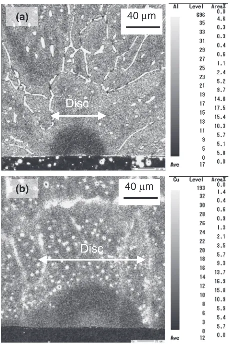
Figure 11 shows the solute distribution on the bottom of the disc shown in Fig. 3. For both alloys, the solute content had a minimum at the center of the disc, and monotonically increased with increasing distance form the center. The solute distribution in the disc obtained in the present work is the same as that in a disc of a specimen poured on a chill cast-iron chill block.16)However, as shown in Fig. 12, the solute
content in the cross section took a local maximum at the center of the disc, decreased with increasing radial distance from the disc center, had a local minimum, and then increased with approaching the boundary between the disc and the predendrite.
The solute distribution was also analyzed for the superdisc on the bottom of the Al2Cu alloy specimen, and as shown in Fig. 13, a high solute content was obtained in the superdiscs. However, the solute content was decreased at the center, which was thought due to disturbance of detection of the secondary electron by the irregularity at the center of the superdisc.
In Table 2, the orientations on the bottom of discs obtained using the micro X-ray diffraction technique are tabulated. In 100 μm
Fig. 9 Dendrite structure on the bottom of the Zn2Al alloy specimen poured at 550°C on the buffed chill block.
500 600 700 800 0
10 20 30 40 50
Pouring temperature, Tp/°C
Disc diameter
,
dd
/
μ
m
Zn 2Al Al 2Cu (a)
500 600 700 800 0
20 40 60 80
Pouring temperature, Tp/°C
Disc number density
,
ρd
/mm
2
Zn 2Al Al 2Cu (b)
Fig. 8 Influence of the pouring temperature on the disc diameter (a) and the areal number density of discs (b) in the alloy specimens poured on the chill block polished with#60 emery paper.
200
μ
m
(a)
100
μμ
m
(b)
[image:5.595.78.262.69.332.2] [image:5.595.62.275.395.554.2]the table, the angle appearing after the crystal axis represents the angle of deviation of crystal axis from the surface normal. This deviation might be caused by a setting error of the
specimen in the X-ray diffraction analysis. According to these analyses, the Zn2Al alloy specimen was oriented along the [0 0 0 1] axis on the bottom, but multiple axes including [1 1 0] and [1 1 0] were observed on the bottom of the Al2Cu alloy specimen. These results were consistent with thefindings of Bower and Flemings19)and Edmunds.20,21)
4. Discussion
4.1 Formation process of the initially solidified structure
When the molten alloy was poured on the copper chill block polished with emery paper, as illustrated in Fig. 14, the initially solidified structure may form on the specimen bottom with three stages as follows:
4.1.1 Generation and growth of discs
In previous reports and the present results, the initially solidified structure grew randomly on the chilled surface for the aluminum alloy, but zinc alloys had the (0 0 0 1) texture on the chilled surface. The probability of the nucleation of the discs is dependent on the size of the critical radius of the disc, which is dependent on the interfacial energy at the solid liquid interface£SLand that at the interface between the solid
and the substrate £SC. When the anisotropy of the energies
£SL and £SC is larger, nuclei with crystal planes of smaller -40 -20 0 20 40
0 1000 2000
Distance from the center, x/ μm
Relative
Al content, C
Al
Disc (a)
-40 -20 0 20 40
0 1000 2000
Distance from the center, x/ μm
Relative Cu content, C
Cu
Disc (b)
Fig. 11 Solute distributions on the bottom of the disc of the Zn2Al alloy specimen (a) and the Al2Cu alloy specimen (b) poured on the chill block polished with#60 emery paper.
(a) 40 μm
(b) 40 μm
Disc
[image:6.595.78.263.69.298.2]Disc
Fig. 12 Solute distributions at the cross section of the disc of the Zn2Al alloy specimen (a) and the Al2Cu alloy specimen (b) poured on the chill block polished with#60 emery paper.
-200 -100 0 100 200
0 1000 2000 3000
Distance from the center, x/μm
Relative Cu content, C
Cu
[image:6.595.334.522.72.182.2]Disc
Fig. 13 Solute distribution on the bottom of the superdisc in the Al2Cu alloy specimen poured at 800°C on the buffed chill block.
Disc Dendrite
Molten alloy
Predendrite
Copper chill Surface dendrite
[image:6.595.310.541.246.463.2]Fig. 14 Schematic representation of the initially solidified structure. Table 2 Orientation on the surface of discs.
[image:6.595.54.284.356.701.2]£SL and£SCmay grow preferably. Therefore, the orientation
distribution of the discs is dependent on the anisotropy of the energies of £SL and £SCof the crystal planes. When the
molten alloy is poured on the chill block, a thin oxide layer is formed on the molten alloy and it has been reported that the aluminum oxide layer formed on the solid aluminum has an amorphous structure22,23)with isotropic properties. Unfortu-nately, there have been no reports on the oxide layer formed on zinc, but it can be expected that the zinc oxide layer formed on the solid zinc will be also amorphous. Therefore the interfacial energy£SCcan be treated as isotropic.
In general, the magnitude of the anisotropy of the interfacial energy £SL is small for a metal with a cubic
crystal structure, and especially, the anisotropy of the interfacial energy£SLof the aluminum alloy is very small.24)
Therefore the interfacial energy £SL of the aluminum alloy
can be treated as isotropic, and the random nucleation of discs is expected on the bottom of the Al2Cu alloy specimen. On the other hand, when the interfacial energy £SLis anisotropic, it considerably affects the nucleation of the
discs. Mariaux and Rappaz25)reported that the anisotropy of the interfacial energy£SLof zinc is so large that the shape of
the nucleus is not spherical but instead lenticular, and when the molten alloy was dropped on the chill block,fine grains with the (0 0 0 1) plane orientation were formed on the surface of the droplet.
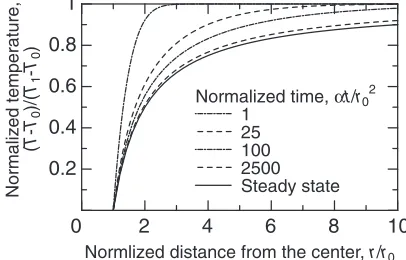
In spite of anisotropy of the solidliquid interface, the temperature distribution controls the shape of the growing disc. Since the temperature distribution is expected to be semispherical, as shown below, the nucleus will grow in a semispherical shape.
The temperature distribution was calculated assuming that only a narrow region of the bottom of the molten alloy contacted to the cusp of the chill block, and that only at this region, heat was transferred from the molten alloy to the chill block. Since the region where the disc contacted to the cusp of the chill block was slightly dented, as shown in Fig. 4, it was assumed to be semispherical in calculation of the temperature distribution. In the casting process, there exists an air gap between the molten alloy and the mold, and the temperature distribution should be calculated in consideration of a heat transfer coefficient at the boundary. However, the heat transfer coefficient changes with elapsed time, and hence it is difficult to obtain the analytical solution of the temperature distribution in consideration of the heat transfer coefficient. Therefore, in the present time, the temperature distribution was analyzed assuming that the boundary was kept at a constant temperature as the first order approxima-tion. Namely, when a molten alloy at temperatureT1comes
into contact with a substrate with a semispherical shape and a radiusr0at a temperatureT0, the temperature distributionT
in the molten alloy is as follows,26) assuming an insulating character of the surface of the molten alloy that is not in contact with the substrate:
Tðr; tÞ ¼T0þ ðT1T0Þ 1rr0erfc r2pffiffiffiffiffi¡rt0
; ð1Þ
where¡ is the thermal diffusivity,ris the distance from the center of contact and t is the elapsed time. The change in the temperature distribution with elapsed time is shown in
Fig. 15. As shown in thefigure, the temperature distribution converges to the steady-state distribution given by,
Tðr; tÞ ¼T0þ ðT1T0Þ 1rr0
: ð2Þ
Following the change in the temperature distribution, the growth rate of the discs decreased rapidly. In addition, the analytical solution of the steady-state is also known for the case that the molten alloy contacted to the cusp with a flat surface.27) In this case, also, the steady-state temperature distribution approaches the semispherical distribution with increasing distance from the bottom of the specimen.
Next, the solute distribution in the disc is discussed. Normally, during the initial transient solidification, a solid phase with a solute content kC0 appears and grows with
increasing solute content at the planar interface,28)wherekis
the partition coefficient at the solidliquid interface and assumed to be less than unity in the present discussion. When the molten alloy was poured on the chill block, however, the solute content decreased in the depth direction, as shown in Fig. 12, which indicates that the solidification might occur form the undercooled liquid in the depth direction. In the case of the solidification along the specimen bottom, the solid-ification might also occur in the undercooled liquid. Since the temperature along the bottom was almost constant, the undercooling might not disappear in a short time but remained for a considerable time during solidification, which might cause the monotonic increase in the solute content on the bottom of the specimen, as shown in Fig. 11. Since the formation of the discs may be highly related to the solidification in the depth direction, the following discussion is focused on the solidification in the depth direction.
Figure 16 describes predicted changes in temperature and solute content in the solid at the interface in the initial transient solidification from the undercooled liquid. When the solidification begins from the molten alloy at an undercooled temperatureT*(<TL), primary crystals appears with a solute
content C* intermediate between kC0 (the initial solute
content for normal initial transient solidification) andC0(the
solute content of the alloy). After the start of the solid-ification, the undercooling of liquid ahead of the solidliquid interface disappears, and the interfacial temperature rapidly increases to the equilibrium temperature and the solute content at the interface decreases. When the solidliquid
2 4 6 8 10
0.2 0.4 0.6 0.8 1
0
Normalized time, αt/r02 1
25 100 2500 Steady state
Normlized distance from the center, r/r0
Normalized temperature,
(
T
-T0
)/(
T1
-T0
[image:7.595.324.527.75.205.2])
interface moves a particular distance, the interfacial temper-ature and the solute content at the interface will approach those observed during the normal initial transient solid-ification (dashed lines in Fig. 16), and the interfacial temperature will begin to decrease and the solute content at the interface will begin to increase. The existence of the local minimum in the solute distribution is coincident with the reports of Biloni and Chalmers,9) Nishi et al.16) and with
the present results in Fig. 12. After the undercooling disappeared, the planar interface became unstable and its morphology transformed.
4.1.2 Generation and growth of predendrite
It is thought that the disc grows with the planar solid liquid interface of the semispherical shape, and while the stability of the planar interface is maintained, the disc enlarges. To analyze the stability of the planar solidliquid interface, the temperature distributions in the solid and the liquid near the interface and also the solute distribution in the liquid ahead of the interface are required. Unfortunately, these distributions are not obtained in the present work. Therefore, the stability of the planar interface during semispherical growth is discussed based on the previous analyses as follows.
Assuming that the bottom of the specimen not in contact with the substrate has insulating character, the planar interface with a semispherical shape can be treated as a planar interface with a spherical shape in terms of stability. The stability of the solidliquid interface for spherical growth has been reported by Mullins and Sekerka29) and Coriell and Parker.30) Mullins and Sekerka29) reported that when spherical growth occurred in a uniformly undercooled liquid, the critical size for planar growth was about 0.3 µm for undercooling to 1/10 of the melting temperature (in terms of absolute temperature). Coriell and Parker30)analyzed
spher-ical growth in undercooled liquid by considering the kinetic term and reported that the critical size of tin is about 3.0 µm. In their analyses,29,30)the liquid was uniformly undercooled,
and the solidliquid interface moved with a negative
temperature gradient, which made the interface unstable. At the initial stage, however, the interfacial energy was relatively large and the planar interface was stabilized. With the progress of the solidification, the solute content was in-creased at the interface. Due to the increase in the solute content, in combination with the negative temperature gradient, the planar interface became unstable in a short time. On the other hand, in the case of the growth of the discs, only the bottom of the specimen was undercooled, but the inside was maintained at a higher temperature. Therefore, after the nucleation of the discs, the undercooling near the discs disappeared rapidly, and a positive temperature gradient in the depth direction appeared at the interface to stabilize the planar interface. From these reasons, the discs might grow larger than the solid sphere in the previous analyses.29,30)
It is known that the planar interface changes to a cellular interface, and hence predendrites with cellular structures grow from the discs that formed through planar growth. Since the cellular structure does not have any preferred orientation but grows depending on the heat flow,31) the predendrites extend in a radial direction depending on the heat flow direction.
4.1.3 Generation and growth of dendrite
The predendrites grow from the disc under varying temperature and solute distributions, and become unstable at some critical conditions to form branches.32,33) At this stage, the predendrites change into the dendrites with a preferred orientation.
Near the bottom of the molten alloy, the temperature is lower than on the inside because of heat transfer to the chill block. In some cases, the bottom of the alloy is undercooled. These situations enhance the growth of the dendrites along the bottom. Since the dendrites grow in a preferred orientation, the growth direction follows the crystal orienta-tion of the disc. In the AlCu alloy specimen, the orientation of the disc is random, and hence the dendrites grow in random directions. In contrast, in the ZnAl alloy specimen, only the discs of the (0 0 0 1) plane are formed on the bottom of the specimen, and hence the primary arm of the dendrite grows along the [1 0 10] direction on the (0 0 0 1) plane34) on the bottom of the specimen. The growth direction of the secondary arm is different from that of the primary arm. In the AlCu alloy specimen, the secondary arm grows along the [0 1 0] direction, which is perpendicular to the primary arm. However, the secondary arm of the ZnAl alloy grows along the [1 1 20] direction at an angle 60° from the primary arm on the (0 0 0 1) plane, and along the [0 0 0 1] direction perpendicular to the basal plane (0 0 0 1). These primary and secondary dendrite arms make up the surface layer on the bottom of the alloy specimen.
4.2 Initially solidified structure on the bottom of the
alloy specimen poured on the buffed chill block
When the molten alloy was poured on the copper chill block polished with emery paper, the disc number density increased with decreasing rugosity, as shown in Fig. 7(b). However, when the rugosity was lowered than 0.54 µm, no discs but fine grains consisting of dendrites appeared on the bottom of the Zn2Al alloy specimen. In contrast, at a rugosity less than 0.27 µm, larger discs formed on the bottom
TI
CSI
TL
T*
kC0
C*
TS
C0
Distance Normal initial transient
[image:8.595.79.260.65.246.2]Normal initial transient
Fig. 16 Changes in the temperatureTIand the solute content C sIin the
solid at the solidliquid interface with distance in the initial transient solidification from the undercooled liquid at a temperatureT*.TLandTS
of the Al2Cu alloy specimen. And, in both alloys, the disc number density increased with increasing pouring temper-ature, as shown in Fig. 8(b).
Appearance of fine grains on the bottom of the Zn2Al alloy specimen poured on the buffed chill block may be explained as follows. The number offine grains in unit area (the areal number density of grains) was about 120 mm¹2, as shown in Fig. 9. When the relation between the disc number density and the rugosity in Fig. 7(b) was extrapolated to
Rq=0.05 µm, which would correspond to the rugosity of the
bottom of the buffed chill block, it was expected to be about 110 mm¹2. The coincidence between the expected disc
number density and the observed areal number density of grains indicates that in the Zn2Al alloy specimen, the number of nucleation sites of the discs increased with decreasing rugosity but smaller grains were formed instead. The reason of smaller grains on the bottom of the Zn2Al alloy specimen can be explained by the increase in the number of disc nuclei due to increase in the heat transfer, as was observed in the alloy specimens poured on the chill block polished with emery paper. Therefore, the disc diameter was so small enough to be comparable to or less than the diameter of the primary arm of the dendrite, so the disc could not be distinguished.
In the Al2Cu alloy specimen poured on the buffed chill block, the superdiscs were formed, but at a very low number density. There are no consistent explanations why the superdiscs appear on the bottom of the Al2Cu alloy specimen, but there are some possible reasons, such as the differences in the surface tension, the wettability, thefluidity and other parameters in both alloy specimens. Here, as one of possible explanations, the influence of the surface tensions in both alloy specimens is discussed as follows. According to the review by Keene,35) the surface tension of liquid
aluminum, 871 mN/m, is larger than that of liquid zinc, 789 mN/m. In addition, when the molten alloy comes in contact with the chill block, an oxide layer is rapidly formed on the molten alloy and aluminum oxide has a higher rigidity than the zinc oxide. Therefore, when the molten AlCu alloy was poured on the chill block, the molten alloy encountered a small number of higher cusps on the chill block and the solidification shrinkage followed to form a gap between the molten metal and the surface of the chill block. This caused a decrease in the number of nucleation sites of the discs, and the discs of very larger size, namely the superdisc, formed.
In addition, as shown in Fig. 13, at the center of the superdisc, the solute content was very high, and it is expected that the discs were formed in the solidification from the greatly undercooled liquid in consideration of the local equilibrium at the solidliquid interface. On the other hand, Takeuchi and Nishi15)reported that the undercooling in the molten alloy was increased with increasing superheat of the molten alloy. Following their results,15)when the molten Al 2Cu alloy was poured at higher pouring temperatures on the buffed copper chill, the undercooling should be smaller, which contradicts the present result. In the present work, it is unable to explain why this contradiction occurred, but the larger undercooling in the present results might be related to the very low number density of the superdiscs.
5. Conclusion
Molten Zn2.54 mass% Al (Zn2Al) and Al2.35 mass% Cu (Al2Cu) alloys were poured on a copper chill block and the initially solidified structures formed on the bottom of the specimens were subjected to metallurgical treatments to obtain the following results.
When the molten Zn2Al alloy was poured, as was observed in the Al2Cu alloy, discs formed on the bottom of the specimen, the predendrites with a cellular structure grew from the discs, and then dendrites grew outside the predendrites. For both alloys, the discs caused protrusions of about 1 µm in height on the bottom of the specimen. The solute distribution in the disc had a local maximum at the center, which indicates solidification from an undercooled molten alloy. The discs had the (0 0 0 1) plane orientation on the bottom of the Zn2Al alloy specimen, but there was no specific orientation of the discs formed on the bottom of the Al2Cu alloy specimen. Dendrites grown on the bottom of the specimen made up the surface layer.
For both alloys, with increasing surface roughness of copper chill blocks polished with emery paper, the disc diameter increased and the disc number density decreased. In addition, the disc diameter and the disc number density both increased with increasing pouring temperature. When the molten alloy was poured on a buffed chill block, no discs were formed on the bottom of the Zn2Al alloy specimen, butfine dendrites grew. In contrast, on the bottom of the Al 2Cu alloy specimen poured on the buffed chill block, larger discs formed at a very low number density. In particular, when the Al2Cu alloy was poured at a temperature of 800°C or higher, two types of the discs appeared on the bottom of the specimen: normal discs of 20 to 30 µm in diameter and very large discs (the superdiscs) of 100 to 200 µm in diameter. Following these results, the formation process of the initially solidified structure was discussed.
Acknowledgements
The micro X-ray diffraction analysis of the disc was carried out at Application Laboratories, Rigaku Corporation. The authors would like to express their thanks to Ms. H. Matsusaka, Mr. Y. Yamada, Mr. R. Yokoyama, Mr. A. Nezu and Mr. Y. Kamimura, Rigaku Corporation. The authors also thank Prof. J. Ikeno and Dr. H. Shibutani of Saitama University for their help in observing the discs with the laser scanning microscope. Our thanks are also due to Mr. Y. Kawada, Technical Support Center, Research & Develop-ment Bureau, Saitama University, for his technical assistance and to Dr. K. Kageyama, Associate Professor, Saitama University for useful discussions. The EPMA analysis of the disc was conducted by Mr. H. Inoue, Saitama Industrial Technology Center (SAITEC).
REFERENCES
1) H. Noguchi, S. Abe and M. Murakawa:J. Japan Soc. Precision Eng.69
(2003) 125129 (in Japanese).
2) S. Abe, H. Noguchi and M. Murakawa: J. Japan Soc. Precision Eng.70
3) J. A. Bardt, G. R. Bourne, T. N. Schmidt, J. C. Ziegert and W. g. Sawyer:J. Mater. Res.22(2007) 339343.
4) J. H. Park, S. O. Choi, R. Kamath, Y. K. Yoon, M. G. Allen and M. R. Prausnitz:Biomed. Microdevices9(2007) 223234.
5) Y. Tang, W. K. Tan, J. Y. H. Fuh, H. Tl. Loh, Y. S. Wong, S. C. H. Thian and L. Lu:J. Mater. Process. Technol.192193(2007) 334339.
6) D. Walton and B. Chalmers: Trans. Met. Soc. AIME215(1959) 447 457.
7) H. Kato and J. R. Cahoon:Metall. Trans. A17(1986) 823832.
8) H. Kato, K. Nakumura, K. Kobayashi and K. Yoshikawa:J. Soc. Mater.
Sci. Japan38(1989) 384390 (in Japanese).
9) H. Biloni and B. Chalmers: Trans. Met. Soc. AIME233(1965) 373 379.
10) M. Prates and H. Biloni:Metall. Trans.3(1972) 15011510.
11) M. Nishi, H. Takeuchi and S. Uchida: IMONO54 (1982) 718724 (in Japanese).
12) M. Nishi, H. Takeuchi and S. Uchida: Proc. School of Eng. Tokai Univ.
23(1983) No. 1, pp. 6167 (in Japanese).
13) H. Takeuchi, N. Nishi, S. Takemoto and M. Kawakami: IMONO56
(1984) 4752 (in Japanese).
14) N. Nishi, H. Takeuchi and S. Uchida: Proc. School of Eng. Tokai Univ.
24(1984) No. 1, pp. 97102 (in Japanese).
15) H. Takeuchi and N. Nishi: J. Japan Inst. Metals48(1984) 633639 (in Japanese).
16) N. Nishi, H. Takeuchi and S. Uchida: Proc. School of Eng. Tokai Univ.
24(1984) No. 2, pp. 7782 (in Japanese).
17) H. Takeuchi, N. Nishi, S. Takemoto and M. Kawakami: Proc. School of Eng. Tokai Univ.24(1984) No. 1, pp. 8996 (in Japanese).
18) H. Takeuchi, S. Takemoto and I. Murashima: J. Japan Inst. Light
Metals35(1985) 562567 (in Japanese).
19) T. F. Bower and M. C. Flemings: Trans. Met. Soc. AIME239(1967) 16201625.
20) G. Edmunds: Trans. TMS-AIME161(1945) 114119. 21) G. Edmunds: Trans. TMS-AIME143(1941) 183197.
22) L. P. H. Jeurgens, W. G. Sloof, F. D. Tichelaar and E. J. Mittemeijer:
Phys. Rev. B62(2000) 47074719.
23) P. C. Snijders, L. P. H. Jeurgens and W. G. Sloof:Surf. Sci.589(2005)
98105.
24) S. Liu, R. E. Napolitano and R. Trivedi:AlCu alloy, Acta Mater.49
(2001) 42714276.
25) A. Mariaux and M. Rappaz:Acta Mater.59(2011) 927933.
26) H. S. Carslaw and J. Jaeger:Conduction of Heat in Solids, (Clarendon Press, Oxford, 1959) p. 247.
27) H. S. Carslaw and J. Jaeger:Conduction of Heat in Solids, (Clarendon Press, Oxford, 1959) p. 215.
28) H. Kato and Y. Ando:Mater. Trans.52(2011) 179188.
29) W. W. Mullins and R. F. Sekerka:J. Appl. Phys.34(1963) 323329.
30) S. R. Coriell and R. L. Parker:Crystal Growth, Proc. Int. Conf. Crystal Growth, Boston, June, 1966, ed. H. S. Peiser, (Pergamon Press, 1967) pp. 703708.
31) W. Kurz and D. J. Fisher:Fundamentals of Solidification, (4th ed.), (Trans Tech Publication Ltd., Switzerland, 1998) p. 68.
32) J. A. Sekhar:Acta Mater.50(2002) 48414845.
33) J. Teng, S. Liu and R. Trivedi:Acta Mater.57(2009) 34973508.
34) M. A. Audero and H. Biloni:J. Cryst. Growth12(1972) 297308.