Precipitation Structure of Al
10 mass
%
Si
0.3 mass
%
Mg Alloy Produced
by High Pressure Die Casting and Permanent Mold Casting with T5 Treatment
Emi Yanagihara
1,+1, Shin Orii
1, Takuya Iketani
2,+2, Seiji Saikawa
3, Kenji Matsuda
3and Susumu Ikeno
41Ahresty Corporation, Toyohashi 441-3114, Japan
2Graduate School of Science and Engineering for Education, University of Toyama, Toyama 930-8555, Japan 3Graduate School of Science and Engineering for Research, University of Toyama, Toyama 930-8555, Japan 4Hokuriku Polytechnic Collage, Uozu 937-0856, Japan
The precipitation structures in as-cast and T5-treated specimens of high pressure die casting and permanent mold casting in Al 10 mass%Si0.3 mass%Mg alloys were investigated using transmission electron microscopy (TEM) and field emission scanning electron microscopy (FE-SEM). No precipitates were observed in any of the as-cast materials. Fine needle-shaped precipitates, coarse rod-shaped precipitates, and granular precipitates were observed in all peak-aged specimens, which are thought to be the main cause of the increase in hardness during T5 treatment. These precipitates becamefiner near the eutectic phases than inside the¡-Al phase cells, because the contact interface between the¡-Al phase and the eutectic Si phase can be considered to become an area of vacancy sink and inhibit the growth of the precipitates. It became clear that almost all the precipitates in the die cast and the permanent mold cast specimens of this alloy were not due to the as-cast heat; rather, they were generated by the T5 treatment. [doi:10.2320/matertrans.M2015100]
(Received March 10, 2015; Accepted April 14, 2015; Published June 25, 2015)
Keywords: aluminumsiliconmagnesium alloy, casting, aging, transmission electron microscopy
1. Introduction
The need for weight reduction has been increasing in the automotive industry, leading to a broadening application of numerous aluminum die cast components. An increasing number of these components are being adopted for critical safety components such as automobile chassis and suspen-sion components.1) Materials adopted for such components
are required to offer a combination of appropriate strength and ductility.
One such material is an Al10 mass%SiMg alloy, which features mechanical properties that are more favorable than those of conventional die cast alloys. Research has progressed regarding this alloy as a highly ductile material that can be applied to automobile chassis and suspension components.2)It has been used to produce actual components on cars manufactured since the latter half of the 1990s. Such actual die cast components were often subjected to T5 treatment (artificial aging after demolding), which is a heat treatment conducted with the intention of improving the mechanical properties of the components. Despite this treatment being an important process in determining the
final characteristics of the die cast component, there are very few studies regarding the age-hardening behavior that occurs during this process.
Through hardness measurements, Yamagata et al.3)
ob-tained the age-hardening curves when T5 or T6 heat treatments were applied to die cast materials using an Al 10 mass%Si0.35 mass%Mg alloy, but they did not study the microstructural changes, which are the main cause of the increase in hardness during heat treatment. Moreover, Inoue
et al.4)applied various types of pre-ageing to Al9 mass%Si
0.3 mass%Mg alloy die cast specimens and performed transmission electron microscopy (TEM) investigation on
specimens that had been T5-treated at 453 K for 10.8 ks. They confirmed the presence of only spherical precipitates measuring 1030 nm in diameter in the matrix phase. However, as no observations of the microstructure were conducted during the as-cast state prior to the T5 treatment, it remains unclear whether the precipitates were generated during the casting stage or the T5 treatment stage.
The objective of this study was to perform TEM investigations on both as-cast and T5-treated specimens of die cast Al10 mass%Si0.3 mass%Mg alloy and thus reveal the age-hardening behavior of this alloy in a series of manufacturing processes from casting to heat treatment. We also conducted a comparative investigation of the die casting method and the permanent mold casting method, which are mass production methods of cast components using this alloy in recent year. The cooling rates of these casting methods are different; the cooling rate of die casting method is more rapid than that of permanent mold casting method. From the comparison of both, the effect of cooling rate on the age-hardening behavior was also investigated.
2. Experimental Procedure
The target composition of the alloy was Al10 mass%Si 0.30 mass%Mg0.015 mass%Sr. Small amounts of Sr were added in order to improve the ductility. To achieve this composition, the following raw materials were weighed: pure Al (with a purity of 99.7 mass%or higher), Al20 mass%Si, pure Mg (with a purity of 99.93 mass% or higher) and Al 10 mass%Sr master alloy. These were then loaded into a graphite crucible heated in an electric furnace, and main-tained at approximately 963 K after melting. The molten volumes were set to approximately 2 kg for the permanent mold casting and approximately 200 kg for the die casting. The molten metal was degassed by inserting argon gas via a lance pipe and then cast. The appearance and evaluation portions of the castings are shown in Fig. 1. The hatched
+1Corresponding author, E-mail: emi_yanagihara@ahresty.co.jp
areas in this figure showed the evaluation portions. The chemical compositions of the alloys derived by the emission spectral analysis method are listed in Table 1. Using a cold-chamber die cast machine with a locking force of 3300 kN, the plate shaped castings shown in Fig. 1(a) was cast at a molten metal temperature of approximately 958968 K, a die temperature of approximately 473503 K, an injection speed of approximately 1.5 m/s and a casting pressure of approx-imately 5355 MPa.5)The die temperature was measured by
surface thermometer in evaluation portion of die. The Y-block shaped casting shown in Fig. 1(b) was cast using the permanent mold casting method in a mold with BN coated on the cavity side at a pouring temperature of approximately 953958 K and a die temperature of 453473 K.6) The die
temperature was measured by surface thermometer in evaluation portion of die and thermocouple installed in the point of approximately 2 mm from the die surface.
Immediately after casting, the castings were removed from their dies (hereafter referred to as “demolding”) when the
temperature of the castings had dropped to approximately 498513 K for die casting (hereafter referred to as the
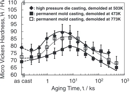
“503 K demolded-DC castings”) and to 473 K and 773 K for permanent mold casting (hereafter referred to as the “473 K demolded-PM castings” and “773 K demolded-PM cast-ings”, respectively). The temperature of the DC castings was measured by surface thermometer in the evaluation portion of the castings just after demolding. On the other hand, the temperature of the PM castings was directly measured by thermocouple installed in the center of the evaluation portion. In the PM casting method, castings were demolded within «3 K from the target temperature. After demolding, the castings were quenched in cold water for 10 s. The procedure continued with a number of small pieces cut off from the evaluation portion while being maintained at room temperature for 172.8 ks (hereafter referred to as the“as-cast materials”) and then subjected to an artificial aging treatment in an oil bath at approximately 472474 K. The peak-aged conditions were chosen from the age-hardening curves5) of the respective castings taken from past measurements (hereafter referred to as the“peak-aged materials”). In other words, the DC castings were set at 3.84 ks and the PM castings were set at 7.68 ks based on the age-hardening curve of 473 K shown in Fig. 2. The three heat patterns at various demolding temperatures and casting processes described above from immediately after pouring until completion of the T5 treatment are shown schematically in Fig. 3.
Small specimens of the individual types of castings and the respective processes described above were polished with waterproof sandpaper, buffed, etched in a 0.5% HF solution and observed under an optical microscope (OM). Observa-tions with a transmission electron microscope (TEM) were also performed by preparing thin-film specimens by electrolytic polishing and then using an EM-002B model microscope manufactured by Topcon at an accelerating voltage of 120 kV. In order to verify the observation position of the TEM, some specimens was also observed using a field emission scanning electron microscope (FE-SEM).
20mm (b)
(a)
50mm
[image:2.595.79.257.69.388.2]Fig. 1 Appearance of the castings produced by (a) high pressure die casting and (b) permanent mold casting process, respectively. The hatched areas show the evaluation portion.
Table 1 The chemical compositions of the alloys (mass%).
Casting process Si Mg Fe Sr Al
high pressure
die casting 10.3 0.29 0.09 0.0113 Bal.
permanent mold casting
10.0 10.4
0.29 0.31
0.15 0.17
0.0057 0.0138 Bal.
60 65 70 75 80 85 90 95 100 105 110
Micro V
ickers Hardness,
H
/ HV
Aging Time, t / ks
as cast 1 101 102 103
: high pressure die casting, demolded at 503K : permanent mold casting, demolded at 473K : permanent mold casting, demolded at 773K
[image:2.595.314.543.73.235.2] [image:2.595.45.292.462.527.2]3. Results
3.1 As-cast materials
The nominal microstructures of the as-cast materials are shown in Fig. 4. Both the DC and PM castings were structured by primary crystallized¡-Al phases (indicated by the white section) and eutectic phases (indicated by the dark gray section). The DC castings arefiner than the PM castings. Furthermore, a significant difference in the shape of the primary crystallized¡-Al phase can be seen: the DC castings are cellular as compared to the PM castings, which are dendritic. The measured secondary dendrite arm spacing of the DC and PM castings were 7.2 and 18.8 µm, respectively. The cooling rates were calculated from the following approximation equation5)with these secondary dendrite arm
spacing.=38 ·CR¹0.34, whereis the secondary dendrite
arm spacing andCRis the cooling rate. The cooling rates for the DC and PM castings were approximately 140 and 10 K/s, respectively, with the DC castings being cooled markedly rapidly.
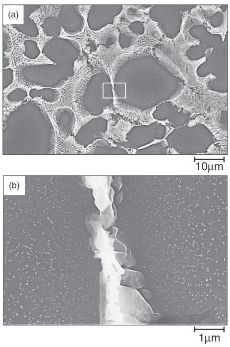
The as-cast materials for the 503 K demolded-DC castings and the 473 K and 773 K demolded-PM castings were electrolytically polished, and the nominal results of the observation using FE-SEM to verify the presence of precipitates in the¡-Al phase are shown in Fig. 5. The dark gray and white region in thisfigure showed the primary¡-Al and the eutectic Si phase, respectively. No precipitates were observed in the primary ¡-Al phase for either casting. However, only in a very small area near the eutectic region, which is thought to be the increasing of solute concentration due to segregation at the last stage of solidification in the evaluation section, in the 473 K demolded-PM castings, rod-shaped or granular precipitates approximately 1 µm or less in Cast, 953K
Cast, 953K Cast, 963K
Demolding, 473K
T
emperature,
T
/ K (b)
(c) (a)
Demolding, 773K Demolding, 503K
Quench
Quench Quench
Aging, 473K
R.T.,172.8ks
R.T.,172.8ks R.T.,172.8ks
Time, t / s
Aging, 473K Aging, 473K
800s
50s 16s
Fig. 3 Heat pattern from casting to subsequent aging, (a) high pressure die castings demolded at 503 K, (b) permanent mold castings demolded at 473 K and (c) permanent mold castings demolded at 773 K.
(a) (b)
(c) (d)
50
μ
m
20
μ
m
[image:3.595.57.284.66.369.2] [image:3.595.134.462.485.759.2]size were observed. Only when the cooling rate was slow and demolding temperature was low, precipitates were observed. Based on these results, it was estimated that these precipitates were generated by the as-cast heat, while the temperature of the castings dropped from 773 K to 473 K after casting. Subsequently, the observation of the specimens at a higher TEM magnification was performed to conduct a more detailed examination.
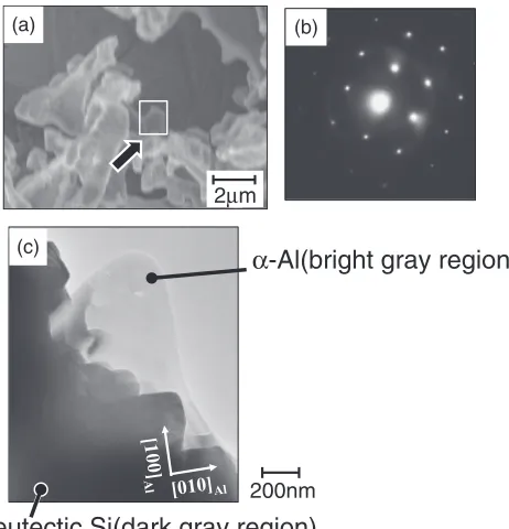
The nominal TEM observational results from electrolytic polishing of the as-cast materials for the 503 K demolded-DC castings, the 473 K demolded-PM castings and the 773 K demolded-PM castings are shown in Figs. 68, respectively. Figures 6(a) and 8(a) show the FE-SEM images of the observed portion using by TEM, white region is the primary
¡-Al phase, the gray region is the eutectic Si phase and the other region is the hole made by electrolytic polishing. The specimens observed by TEM had some holes in the primary
¡-Al phase. The observations were conducted in thinfilmed portions near the holes. In the bright-field image of the 503 K demolded-DC castings shown in Fig. 6(c); the bright gray region shows the primary ¡-Al phase, the dark gray region shows the eutectic Si phase and the other region shows the hole made by electrolytic polishing, no precipitates are observed in the ¡-Al phase. Similarly, in the bright-field image of the 473 K demolded-PM castings shown in Fig. 7(a), no precipitates are observed except for what appeared to be dislocation lines in the upper section of the photograph. The same is also true for the bright-field images of the 773 K demolded-PM castings shown in Figs. 8(c) and (d): no precipitates are found at location c in the center of the
¡-Al phase or location d near the eutectic phase except for dislocation lines. Focusing on Figs. 6(b), 7(b), and 8(b), which are the selected area diffraction patterns from the respective bright-field images in Figs. 68 described above, the principal point to note is the diffraction spots of the¡-Al
phase, which were confirmed in all cases. No clusters or streaks from the production of the GP zone during the very initial stage of aging were observed in any of these cases. Since no precipitates were present in the ¡-Al phase, it is apparent that in the case of rapid solidification of the die cast materials, no precipitates were generated by the as-cast heat.
3.2 Peak-aged materials
The nominal results of the observations conducted using High pressure die casting Permanent mold casting
503K
473K
773K
Low magnification
High magnification
1
μ
m
10
μ
m
Fig. 5 Micrographs by FE-SEM of high pressure die castings demolded at 503 K and permanent mold castings demolded at 473 K and 773 K under the as-cast condition using by electrolytic polishing. The square positions in SEM image were observed with high magnification.
(a) (b)
200nm
α
-Al(bright gray region)
eutectic Si(dark gray region)
(c)2μm
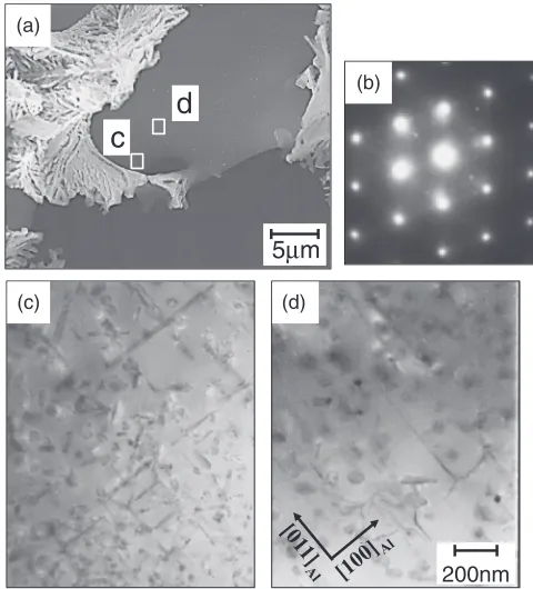
[image:4.595.311.542.370.610.2]TEM on the ¡-Al phase of the three types of castings for which peak aging was performed at 473 K are shown in Figs. 911. The observation results for the 503 K demolded-DC castings are shown in Fig. 9. Observations were performed using TEM at two locations, namely, locations c and d, which are shown in the SEM image [Fig. 9(a)]. The TEM results for the two locations are shown in Figs. 9(c) and 9(d), respectively. The¡-Al phase [Fig. 9(d)] shows granular precipitates approximately 5080 nm in diameter and rod-shaped precipitates, which are generally considered to have exceeded 200 nm in length. Next, varying precipitation conditions can be seen in the upper and lower sections of the bright-field image shown in Fig. 9(c) near the eutectic phase. In the upper section of the micrograph, relatively coarse rod-shaped and granular precipitates similar to those found inside the¡-Al phase [Fig. 9(d)] are seen. However, in the lower section of the micrograph, which is near the eutectic phase, fine needle-shaped precipitates slightly less than approximately 100 nm in length and granular precip-itates approximately 30 nm in diameter are observed.
Three types of precipitates, namely, granular precipitates with diameters of approximately 50 nm, coarse rod-shaped precipitates approximately 200300 nm in length and fine needle-shaped precipitates approximately 50 nm in length were observed in cells of the ¡-Al phase in the 473 K demolded-PM castings shown in Fig. 10(c).
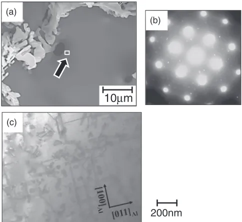
Observations were conducted at two locations for the 773 K demolded-PM castings, which had a high demolding temperature, one near the eutectic Si and the other inside the cell of the ¡-Al phase. The results are shown in Figs. 11(b) and 11(c). Three types of precipitates were observed in the cell of the¡-Al phase shown in Fig. 11(c), namely, relatively
(c) (d)
c
(b)
200nm (a)
10μm
d
Fig. 8 Transmission electron micrograph of permanent mold castings demolded at 773 K under the as-cast condition. (a) FE-SEM images of the observed portion using by TEM, (b) diffraction pattern, (c) and (d) bright
field image observed in square portions in (a).
200nm
(a)
(b)
Fig. 7 Transmission electron micrograph of permanent mold castings demolded at 473 K under the as-cast condition. (a) Brightfield image and (b) diffraction pattern.
(a)
(b)
(c) (d)
c
5
μ
m
200nm
d
[image:5.595.305.545.70.335.2] [image:5.595.91.243.71.402.2]coarse rod-shaped, granular, and fine needle-shaped precip-itates, similar to the precipitates observed in the 473 K demolded-PM castings described above. On the other hand, only fine needle-shaped precipitates measuring approxi-mately 100 nm in length were found in large numbers and in parallel to the [100] direction of the matrix phase and approximately 4 µm from the observed location of Fig. 11(c) and near the eutectic Si shown in Fig. 11(b). From the comparison between Fig. 9(d), Fig. 10(c) and Fig. 11(c), the precipitation conditions in the¡-Al phase were similar for die cast and permanent mold cast specimens.
4. Discussions
As mentioned in the introduction, only a few studies have been conducted on the aging precipitation behaviors of hypoeutectic AlSi alloys that contain a highly concentrated amount of solute Si close to the eutectic composition, such as the Al10 mass%Si0.3 mass%Mg alloy investigated in this study. In recent years, only Inoue et al.4) conducted TEM observations in the matrix phase (primary¡-Al phase) of Al 9 mass%Si0.3 mass%Mg alloy die cast specimens after performing preliminary aging with various time periods and temperatures, as well as T5 treatment (artificial aging treatment after casting) at 453 K for 10.8 ks. Afterwards, only spherical precipitates measuring 1030 nm in diameter were directly observed using TEM. On the other hand, Saikawaet al.6)used TEM to observe the microstructures of
permanent mold castings of Al10 mass%Si0.3 mass%Mg alloys (similar to the one used in this study) which subjected to T5 treatment, and they reported that the lengths and distributions of the rod-shaped and granular precipitates were significantly different at two different locations within the thin-film specimens. However, these reports did not mention what types of precipitation phases were generated within the structures during raw casting or during the subsequent T5 treatment. It is therefore not clear whether the as-cast solidification structure has an effect on those states or not.
In order to clarify such issues in this study, thin-film specimens were observed by TEM and FE-SEM, to clarify the observation locations with TEM in structures, as shown in Fig. 9 and 11. A significant variance in the precipitation conditions, as shown in Fig. 11, was confirmed between two locations for the peak-aged materials, one at the center of the primary crystallized¡-Al cellular phase and the other near the eutectic phase of the 773 K demolded-PM castings prepared by permanent mold casting. On the other hand, for the as-cast materials, neither location showed precipitates. These results are similar to those of the 503 K demolded-DC castings prepared by high pressure die casting.
In order to conduct more detailed observations on such variances of the precipitation conditions, electrolytic polish-ing was performed on the peak-aged materials of the 503 K demolded-DC castings to facilitate observation of the precipitation phase using FE-SEM. The nominal results are shown in Fig. 12. Although rod-shaped, needle-shaped, or granular precipitates occurred almost throughout the entire
¡-Al phase, the precipitates observed in the range of approximately 1 µm from the eutectic phase were more refined, which matches the TEM results shown in Fig. 9. The 200nm
(c)
(b) (a)
[image:6.595.48.290.70.292.2]10
μ
m
Fig. 10 Transmission electron micrograph of permanent mold castings demolded at 473 K and then aged at 473 K for 7.68 ks. (a) FE-SEM images of the observed portion using by TEM, (b) diffraction pattern and (c) brightfield image observed in square portions in (a).
(d) (e)
(b) (c)
200nm 5μm
(a)
[image:6.595.50.290.373.741.2]b
c
presence of a refined precipitated phase near the eutectic region has hardly been reported until now. However, similar phenomena were observed in an AlZnMg alloy (e.g. extra super duralumin) subjected to over-aging; there were high-density precipitates in the inner grain and low-high-density and precipitation free zones near the grain boundaries.7)One of the reasons for this phenomenon is that the grain boundaries acted as vacancy sinks. The refining of the precipitates at the
¡-Al phase near the eutectic phase for the Al10 mass%Si Mg alloy after the T5 heat treatment in this study, namely, the delay in the growth of the precipitates similar to the production mechanism of the precipitation free zones in the AlZnMg system alloy described above, may be explained if the contact boundary of the¡-Al phase and the eutectic Si phase became a vacancy sink location, thereby inhibiting the growth of precipitates.
Finally, the precipitates observed in the peak-aged materials in this study are considered. In the case of the die castings observed in Fig. 9 and the permanent mold castings shown in Figs. 10 and 11, the streaks attributed to the production of GP zones were not observed in the selected area diffraction patterns [Figs. 9(b), 10(b), 11(d) and 11(e)] taken from the ¡-Al phase, irrespective of the differences of the precipitation conditions depending on their locations. On the other hand, finer diffraction spots in the ¡-Al phase were observed in all cases, and these are estimated to have
diffracted from the rod-shaped, needle-shaped and/or granular precipitates. Since these diffraction spots were clear and free of any streaks, these were considered to have different crystal structures from the fcc structure of the A1 matrix phase.
Figure 13 shows the nominal results of the EDS analysis of a precipitate and the bright-field image attained by TEM for the peak-aged materials of the 773 K demolded-PM castings. Portion (2) shows the results of the¡-Al phase that was analyzed as a base, where 3.50 at% Si and 2.05 at%Mg were detected from the matrix phase. In contrast, the amount of Mg detected in precipitates of the fine rod shapes of portion (1), the coarser rod shapes of (3) and the granular shapes of (4) were between 1.532.43 at%, which were not large differences in concentration as compared to the matrix phase. However, in all cases, the amount of Si was 7.60 34.2 at%, which is significantly higher than that of the matrix phase in portion (2). Therefore, all three types of precipitates contained more than a certain concentration of Si, as well as a certain amount of Al and/or Mg (depending on the situation, more could be contained in the precipitate). From the shape of the precipitates with similar properties, as shown in Figs. 9 and 11 above, precipitates similar to the peak-aged materials in the permanent mold castings were thought to be produced like the die cast alloy. Inoueet al.4)reported that the spherical
precipitates observed in Al9 mass%Si0.3 mass%Mg alloy die cast specimens contained a significant amount of Si, which is consistent with the analysis results of this study. Based on the shape of the precipitates, the granular
1
μ
m
10
μ
m
(a) [image:7.595.333.519.66.375.2](b)
Fig. 12 Micrographs by FE-SEM of the high pressure die castings demolded at 503 K and then aged at 473 K for 3.84 ks. (a) Low magnification and (b) high magnification in square position.
portion
Mg
Al
Si
Fe
1
2.01
63.8
34.2
0.00
2
2.05
94.3
3.50
0.105
3
2.43
90.0
7.60
0.00
4
1.53
68.5
29.9
0.00
1
2
3
4
(a)
(b)
at%
[image:7.595.53.285.67.417.2]500nm
precipitates observed in this study can be considered to correspond to that. Since the three differently shaped precipitates observed in this study were not seen in the as-cast materials, it can be surmised that none of the precipitates were generated in the as-cast phase but were instead precipitated by applying the subsequent T5 treatment. It was considered that these precipitates were the main cause that the hardness was increased during T5 treatment in DC and PM castings using by this alloy.
5. Conclusions
The precipitation structures of high pressure die castings and permanent mold casting of an Al10 mass%Si0.3 mass%Mg alloy under as-cast and peak-aged conditions were investigated. The age-hardening behavior of this alloy through a series of manufacturing processes from casting to T5 heat treatment was considered. The results are summa-rized as follows:
(1) Although precipitates were generated in the as-cast phase only in a very small part near the eutectic region, which was thought to be the increasing are of solute concentration due to segregation at the last stage of solidification, it has been revealed that they would not be generated through rapid solidification in the case of die castings.
(2) In peak-aged materials, three types of precipitates were observed, namely, coarse rod-shaped precipitates, fine needle-shaped precipitates and granular precipitates. The shapes of the precipitates were similar for the die castings and permanent mold castings. These precip-itates are thought to be the main cause of the increase in hardness during the T5 treatment.
(3) In the peak-aged die castings, the precipitates arefiner
at a distance approximately 1 µm from the eutectic region when compared to the inside of the¡-Al phase cells, and the density was lower. This is similar to the mechanism that generates a precipitate free zone near the grain boundaries in AlZnMg materials, where the contact interface between the primary ¡-Al phase and the eutectic Si phase is thought to become the location of vacancy sinks and inhibit the growth of precipitates.
(4) For castings manufactured by permanent mold casting and die casting with a cooling speed of approximately 10140 K/s, it was revealed that most of the precip-itates were not generated during the as-cast phase but rather during the subsequent T5 treatment.
Acknowledgments
The authors would like to express their thanks to Mr. Goshi Aoshima and Shota Komura, who were graduate student of University of Toyama, for their help in this study.
REFERENCES
1) M. Ebisawa:J. JILM53(2003) 176181.
2) K. Kanasashi, M. Tashiro, N. Suzuki, S. Matsumoto, M. Katsukura and K. Itakura:J. JILM59(2009) 148153.
3) H. Yamagata and T. Kitsunai: 2006 Japan Die Casting Congress, (Japan Die Casting Association, 2006) pp. 237246.
4) T. Inoue, M. Goto, A. Yamaguchi, T. Otake, A. Kuroda and M. Yoshida:
J. JILM61(2011) 507512.
5) E. Yanagihara, S. Takeda, S. Saikawa, K. Matsuda and K. Terayama: 2012 Japan Die Casting Congress, (Japan Die Casting Association, 2012) pp. 145151.
6) S. Saikawa, R. Morioka, K. Matsuda, K. Terayama and S. Ikeno:J. JILM
64(2014) 457462.