Microstructural Evolution of As-Cast 3.5
%
NiCrMoV Steel Containing
Centimeter-Scale Grain Structure during Reheating and Plastic Deformation
Wen Long Zhao
1,2,+and Qing Xian Ma
1,21Department of Mechanical Engineering, Tsinghua University, Beijing 100084, China 2Key Laboratory for Advanced Materials Processing Technology of Ministry of Education,
Tsinghua University, Beijing 100084, China
Given the importance of microstructure on the mechanical properties of heavy forgings, the typical microstructure of as-cast 3.5%NiCrMoV steel was confirmed through the dissection of a 380 ton ingot as centimeter-scale grains. Subsequent investigation into the change of this grain structure during forging determined that temperature plays a predominant role in not only breaking up centimeter-scale grains into equiaxed grains, but also controlling the extent to which equiaxed grains are refined. This means that afine grain structure with an average grain size of less than 60 µm is formed at 900 and 1000°C, whereas coarse grains are usually retained at 1100 and 1200°C. Moreover, at higher temperatures such as 1200°C, centimeter-scale dendrites are completely crushed by a reduction ratio greater than 30%. Grain size homogeneity is improved by dynamic recrystallization (DRX) at a reduction ratio of 10%, but these grains exhibit anisotropy when the reduction ratio is increased to 40%. Microstructural evolution was also found to be influenced by grain growth during reheating, with a significant increase in grain size not observed between 1000 and 1150°C, but grain coarsening occurring at 950°C. Taking into account the complexity and duality of this microstructural evolution, it is concluded that the deformation parameters and reheating conditions of heavy forgings need to be carefully controlled to ensure an appropriate microstructure is formed. [doi:10.2320/matertrans.M2014080]
(Received March 4, 2014; Accepted July 25, 2014; Published September 12, 2014)
Keywords: forging, heat-resistant steel, centimeter-scale grain structure, microstructural evolution, grain growth
1. Introduction
The development of advanced equipment for the manu-facturing industry tends now to be categorized as either ultra-micro scale or ultra-large scale.1) For example, equipment
used for generating electric power has seen an increasing demand for capacity that continues to raise the tonnages of the heavy ingots and forgings used in the construction. This has inevitably led to larger and more severe defects such as non-metallic inclusions, segregation, shrinkage and porosity; however, it is the excessive retention of coarse original grains that is particularly problematic, as concerns regarding abnormal mechanical properties can result in heavy forgings being scrapped.
In China, research into heavy ingots and forgings has been mostly focused on 3.5%NiCrMoV steel due to its excellent physical properties. This has resulted in a number of valuable
findings, with Chen et al. determining the parameters of austenite transition and pearlite transformation2) and Wang et al.applying a JC model to describe the behavior during the upsetting process.3) The hot deformation behavior during
multi-pass forging was also investigated by Liuet al.4,5)and
the microstructural evolution has been described in detail through the work of Chen,6)Zhang7)and Chen810)et al.On
the basis of kinetic models for dynamic, metadynamic and static recrystallization, a cellular automaton has also been successfully developed to simulate microstructural evolution during forging. Zhang11)and He12)et al.have also studied the effects of temperature, reduction ratio and strain rate on the mechanism and recovery of faults in 3.5%NiCrMoV steel.
However, despite all that is known about the micro-structural evolution of 3.5%NiCrMoV steel, changes in the as-cast coarse grain structure during forging have been rarely reported. This represents a significant oversight in light of the
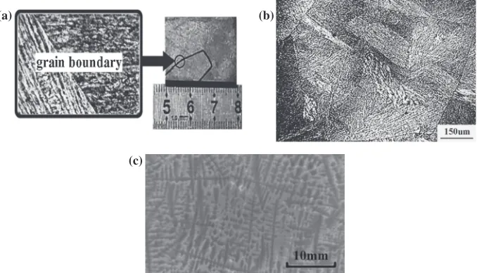
fact that in China the 3.5%NiCrMoV steel ingots used to create low-pressure rotors for 1000 and 1400 MW advanced passive pressurized water reactors (AP1000 and CAP1400) have already reached levels of 500 and 715 tons, respectively. Furthermore, the microstructure of as-cast 3.5%NiCrMoV steel has been identified through sectioning of a 380 ton ingot (Fig. 1) as comprising centimeter-scale columnar grains, equiaxed grains and dendrites, a structure that is considered detrimental to the mechanical properties of processed steels. Full refinement of the grain structure is therefore clearly needed to meet the high-performance requirements of low-pressure rotors, and thus this study is aimed at improving the output of nuclear power units in China through a greater understanding of how centimeter-scale grains are changed by heating and deformation.
2. Experimental Procedure
The majority of experimental work was conducted using as-cast 3.5%NiCrMoV steel derived from a 380 ton ingot used in the production of a 1000 MW low-pressure turbine rotor, which provided the necessary centimeter-scale grain structure. The chemical composition of this steel (in mass%) was measured as 0.28 C, 0.02 Mn, 0.01 Si, 0.003 P, 0.003 S, 1.72 Cr, 0.41 Mo, 3.63 Ni and 0.11 V, with Fe making up the balance. Cylindrical specimens were machined from this material to a diameter of 30 mm and a height of 45 mm, with some being then heated to 900, 1000, 1100 or 1200°C and compressed at reduction ratios of 0, 10, 20, 30, 40 or 50%. The remaining specimens were heated to 850, 900, 950, 1000, 1050, 1100, 1150 or 1200°C at a rate of 5°C/min, and were then held at temperature for 1 or 3 h so as to investigate the microstructural evolution during reheating. All specimens were immediately quenched in 25°C water to retain the grain boundaries of the austenitized grains formed at high temper-atures, and after being longitudinally sectioned and
ically polished, were then chemically etched in C6H3N3O7
H2O. Finally, the microstructure of each specimen was
observed using optical metallography (OM) and transmission electron microscopy (TEM).
To corroborate the existence of dendrite segregation observed in the microstructures, the as-cast specimens were
first cooled by immersing in liquid nitrogen for 30 min. Following fracture, these specimens were immediately analyzed by auger electron spectroscopy (AES) to determine the micro areas of the grain boundary and/or grain interior.
3. Result and Discussion
3.1 Change of centimeter-scale grain structure
In the metallographic images of the specimens deformed at 1100°C (Fig. 2), the change in structure from the original as-cast material (Fig. 1) that is evident in the specimen heated without deformation can be attributed to austenite trans-formation. This transformation creates equiaxed grains by crushing the original centimeter-scale grains, thereby reduc-ing the grain size to 100 µm but also creatreduc-ing an inhomoge-neous grain size distribution (Fig. 2(a)). During the initial
stages of forging, wherein DRX is induced by a reduction ratio of 10%, the grain size homogeneity is improved, as shown in Fig. 2(b). However, as deformation proceeds from 20% (Fig. 2(c)) to 30% (Fig. 2(d)), grain growth tends to dominate the microstructural evolution and the grains begin to elongate under axial pressure. With further increase in the reduction ratio, the grains continue to elongate to the extent that they are transformed into fibrous tissue, as shown in Fig. 2(e). Figure 2(f ) shows that at a reduction ratio of 50% some of these elongated grains become distorted, a phe-nomenon that severely affects the mechanical properties of heavy forgings.
The plot of the average grain size in the primary deformation zone of each specimen as a function of temperature and reduction ratio, as shown in Fig. 3, demonstrates the extent to which the refinement of equiaxed grains is determined by temperature rather than reduction ratio. Specifically, centimeter-scale grains crushed by aus-tenite transformation (reduction ratio of 0%) are converted during forging to finer grains of less than 60 µm in size at temperatures of 900 and 1000°C; however, the coarse grain structure is usually retained at temperatures above 1100°C.
(a) (b)
(c)
Fig. 1 Centimeter-scale grains: (a) columnar grain, (b) equiaxed grain, (c) dendrite.
(a) (b) (c)
(d) (e) (f)
[image:2.595.130.469.72.266.2] [image:2.595.104.491.301.487.2]There are two major factors that influence this grain refinement: (1) DRX tends to be induced by plastic deformation in 3.5%NiCrMoV steel at temperatures between 900°C and 1200°C,4,8)but thefiner grains produced increase
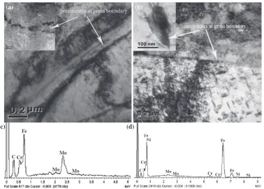
the initial grain boundary area. As a result, the point at which the nucleation of DRX is induced during subsequent deformation increases in accordance with the rate of nucleation. (2) Grain boundary precipitation is shown in Fig. 4(a) to occur at 900°C, but at 1000°C a smaller number of larger precipitates is produced (Fig. 4(b)). Subsequent EDS analysis of these TEM images (Fig. 4(c) and Fig. 4(d)) revealed that these precipitates contained a large amount of Mo and C relative to the composition of the metal matrix, and are therefore identified as MoC. With any further increase in temperature above 1100°C, the grain boundaries
become devoid of any precipitates. This significantly gives the fact that grain boundary precipitates prevent grain boundaries from sliding and inhibit grain growth during forging, thereby providing an explanation for the fine grain size observed at 900°C.
As for the reduction ratio, this has both a positive and negative effect on the evolution of the centimeter-scale grain structure depending on the stage of deformation. For instance, DRX is induced at a reduction ratio of 10% at each of the tested temperatures, thereby improving the grain size homogeneity. On the other hand, the grains become markedly elongated and exhibit anisotropy at reduction ratios above 40%. A brief description of the evolution of the centimeter-scale grain structure of a 3.5%NiCrMoV steel ingot is provided in Fig. 5.
Fig. 3 Grain sizes at different temperatures and reduction ratios.
(a)
(c) (d)
(b)
Fig. 4 TEM and EDS analysis of the grain boundary precipitation: (a) precipitates at 900°C, (b) precipitate at 1000°C, (c) EDS analysis of the precipitates, (d) EDS analysis of the metal matrix.
(a)
(f)
(b)
(e)
(c)
(d)
[image:3.595.62.278.66.234.2] [image:3.595.310.546.70.219.2] [image:3.595.112.490.287.557.2]3.2 Centimeter-scale dendrite crushing
[image:4.595.128.467.70.196.2]From the AES analysis results shown in Fig. 6 and Table 1, it is evident that the atomic concentration of major elements such as Fe, C, V and Ni differ between dendrite locations. This implies that dendritic segregation does indeed occur in as-cast 3.5%NiCrMoV steel, which means that residual dendrites should not be allowed in heavy forgings. The standards for residual dendrites are primarily based on the extent of their transformation to fibrous tissue, but also give some consideration to their crushing through a process of upsetting.13)In this, the metal matrixflows radially under
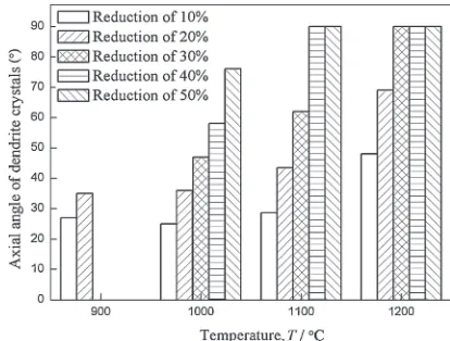
axial pressure, with the resulting fibrous tissue being distributed radially. Macro dendrites can be observed in the axial sections of the etched specimens shown in Fig. 7, with the increase in their average axial angle with temperature at a constant reduction ratio confirming radialflow. Meanwhile, it can be seen from Fig. 8 that the higher the temperature the
more thoroughly the dendrites are crushed, with a combina-tion of high temperature and reduccombina-tion ratio being partic-ularly conducive to eliminating dendrites completely. This is also evident in Fig. 9, which clearly shows that with deformation at 1200°C all dendrites are effectively crushed by a reduction ratio of 40%.
[image:4.595.321.528.227.384.2] [image:4.595.46.290.241.284.2]Fig. 6 AES results of main elements at different locations of dendrites.
Table 1 Atomic concentrations of main elements (%).
Area No. C S V Fe Ni
1 33.49 0.21 0.57 50.69 2.18 2 53.11 0.29 1.35 22.95 1.12
Fig. 7 Average axial angles of dendrites deformed at different temperatures and reduction ratios.
(a) (b) (c) (d)
Fig. 8 Dendrite morphology at reduction ratio of 10%and different temperatures: (a) 900°C, (b) 1000°C, (c) 1100°C, (d) 1200°C.
(a) (b) (c) (d)
[image:4.595.101.494.524.654.2] [image:4.595.106.485.684.772.2]3.3 Grain growth during reheating
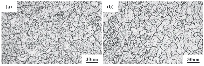
Figure 10 plots the variation in measured grain size with temperature and heating time, revealing an approximate step function with increasing temperature, but very little change in response to heating time. It is also evident that very rapid grain growth occurs at temperatures between 900 and 1000°C, which has been officially termed grain coarsening. Beyond this, the curve levels off between the temperatures of 1000 and 1150°C, but then rises sharply at 1200°C. The microstructures of the specimens heated for 1 and 3 h at 850°C are presented in Fig. 11, which reveals a small increase in average grain size from 9.95 to 10.77 µm that is indicative of a maximum grain size existing for each temperature.
A new kinetic model for grain growth is proposed based on the Sellars and Anelli models that can be described by the following equation:1416)
DtnD0n¼Atmexp RTQ
ð1Þ
whereD0is the initial grain size,Dtis thefinal grain size,tis
the heating time, Q is the activation energy, R is the gas constant (8.318 J mol¹1K¹1), T is the absolute temperature, and A,mand nare all material constants.
Taking the logarithm of both sides of eq. (1) gives:
lnðDtnD0nÞ ¼lnAþmlntRTQ ð2Þ
By substituting the values ofD0,Dt,tandTfor all of the
test conditions into eq. (2), the sum of the squared error can be expressed as:
yðnÞ ¼181:3156137:15599nþ37:94652n2
7:76337n3þ1:73861n40:20495n5þ0:00991n6 ð3Þ
By regressing the minimum sum of the squared errory(n), a value ofn=2.997 is obtained. The values ofQ,mand A
can then be calculated respectively as being 321473 J/mol, 0.341 and 1.665©1017, just as shown in eq. (4). Finally, the kinetic model for grain growth is expressed as:
Dt2:997D02:997¼1:6651017t0:341exp 321473RT
ð4Þ
The grain size calculated by eq. (4) was compared against the experimentally obtained values for each of the different conditions, as shown in Fig. 12. On the basis of this, it is concluded that this kinetic model provides an accurate and true reflection of grain growth in 3.5%NiCrMoV steel, and therefore provides a sound theoretical basis for numerically simulating microstructural evolution during reheating.
3.4 Influence of temperature and reduction ratio on the microstructure of heavy forgings
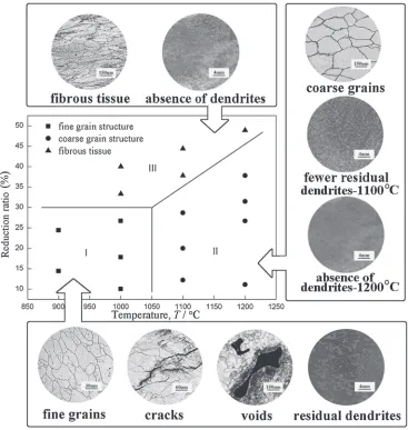
[image:5.595.320.535.65.233.2]The microstructures formed during forging can be divided into three broad categories, as shown in Fig. 13. Zone I represents afine grained structure that conforms to Chinese quality standards for generator rotors; however, the combi-nation of low temperature and limited deformation is ineffective in eliminating voids, and can easily lead to crack initiation and residual dendrites. Indeed, cracks were observed in four of thefive specimens deformed at 900 and 1000°C, whereas no cracks were observed in the specimens
Fig. 10 Grain growth curve of 3.5%NiCrMoV steel.
[image:5.595.54.290.69.239.2](a) (b)
Fig. 11 Microstructures of different heating time at 850°C: (a) 1 h, (b) 3 h.
[image:5.595.126.470.276.388.2]forged at temperatures above 1100°C. Zone II is defined by the coarse grains that come into being between 1100 and 1200°C, but when the higher temperature is combined with an appropriate reduction ratio, it is more effective in eliminating dendrites and voids. Finally, Zone III coincides with a reduction ratio of 30%, and is regarded as the critical deformation point beyond which equiaxed grains are elongated and develop into fibrous tissue. Thus, although the grain structure is relatively finer than in Zone II, the resultant heavy forgings will exhibit anisotropic mechanical properties.
In practical applications, an ingot is typically subjected to multiple deformations and heating/cooling cycles throughout the forging process, which means that previously refined grains may be altered and the ultimate microstructure can be quite difficult to predict. Thus, microstructural evolution is characterized by a combination of complexity and duality that can be interpreted as the conversion between a coarse grain and fine grain structure, which closely bound up with the forging and reheating conditions. Based on the above analysis of the manner in which the microstructure is affected, it is suggested that an initial forging 3.5%NiCrMoV steel ingots at a temperature above 1100°C is optimal to ensure the complete absence of dendrites and the recovery of faults. Subsequent forging at a temperature between 900 and
1000°C, and with a reduction ratio of 10 to 15%, can then be applied to form a fine grain structure with a homogeneous grain size distribution. In any event, the temperature of reheating should be kept lower than 1150°C in order to prevent severe coarsening of thefine equiaxed grains.
4. Conclusions
Through investigation of changes in the centimeter-scale grain structure of a 3.5%NiCrMoV steel ingot during forging and reheating, the following conclusions have been drawn:
(1) The extent to which centimeter-scale grains are refined is determined by the temperature of forging; with fine equiaxed grains less than 60 µm in size formed at 900 and 1000°C due partly to grain boundary precipitation, while a mean grain size of more than 100 µm is produced at 1100 and 1200°C. DRX can be induced at a reduction ratio as low as 10%, and this leads to a homogeneous grain size distribution. With an increase in reduction ratio to 40%, however, the generation of
[image:6.595.115.482.69.456.2]fibrous tissue causes anisotropic mechanical properties. (2) Temperatures lower than 1100°C result in centimeter-scale dendrites being retained, but these are totally absent at 1200°C when accompanied by a reduction ratio of 30% or more, thereby eliminating the adverse
impact of dendritic segregation on the performance of heavy forgings.
(3) Grain coarsening of 3.5%NiCrMoV steel during reheating first occurs at about 950°C, and is followed by steady grain growth up to a temperature of 1000 to 1150°C. A maximum grain size exists at all temper-atures, and grain growth can be defined by the kinetic model:
Dt2:997D02:997
¼1:6651017t0:341exp 321473 RT
Acknowledgements
The authors gratefully acknowledge financial support from National Basic Research Program of China (2011CB012903).
REFERENCES
1) G. B. Zhang: CHN. Equip.4(2008) 4851.
2) R. K. Chen, J. F. Gu, L. Z. Han and J. S. Pan: Trans. Mater. Heat. Treat. 34(2013) 170174.
3) Y. P. Wang, C. J. Han, C. Wang and S. K. Li:J. Mater. Sci.46(2011) 29222927.
4) X. Liu, Y. X. Zhong, Q. X. Ma and C. L. Yuan: Chin. Mech. Eng.21 (2010) 603606.
5) X. Liu, Y. X. Zhong, Q. X. Ma and C. L. Yuan: J. Plast. Eng.17(2010) 115119.
6) S. J. Chen, F. Chen and Z. S. Cui: Die. Mould. Technol.5(2009) 38 40.
7) X. X. Zhang, Y. H. Sun and Y. L. Zhu:Adv. Mater. Res.317319
(2011) 170173.
8) F. Chen, Z. S. Cui and S. J. Chen:Mater. Sci. Eng. A528(2011) 5073 5080.
9) F. Chen, Z. S. Cui, D. S. Sui and B. Fu:Mater. Sci. Eng. A540(2012) 4654.
10) F. Chen, Z. S. Cui, J. Liu, J. Liu, X. X. Zhang and W. Chen:Model. Simul. Mater. Sci. Eng.17(2009) 075015.
11) X. X. Zhang, T. Lin, S. S. Zhu, S. L. Zhang, Z. Wang and L. Ha:Appl. Mech. Mater.184185(2012) 854857.
12) J. L. He, Z. S. Cui, F. Chen, Y. H. Xiao and L. Q. Ruan:Mater. Des.52
(2013) 547555.
13) H. P. Shao: Des. Manuf. Diesel. Engine.4(1997) 5455.
14) L. Q. Chen, F. L. Sui and X. H. Liu: Acta Metall. Sin.45(2009) 1242 1248.
15) C. M. Sellars and J. A. Whiteman:Mater. Sci. Technol.13(1979) 187 194.
16) C. Devadas, I. V. Samarasekera and E. B. Hawbolt:Metall. Trans. A22