Deformation and Recrystallization of Aluminum Bicrystals
Having Asymmetric Tilt Grain Boundary
Tatsuya Okada, Masashi Kotaka
*1, Tetsuya Wada
*2, Minoru Tagami and Fukuji Inoko
*3 Department of Mechanical Engineering, Faculty of Engineering, Tokushima University, Tokushima 770-8506, JapanTwo types of aluminum bicrystals (Bicrystal 1 and 2) having an asymmetric tilt grain boundary were grown. In Bicrystal 1, the orientations of component grains were related to each other by 45rotation about the normal of the wide surface of the tensile specimen. In Bicrystal 2,
although the primary slip planes were symmetric about the grain boundary plane, the component grains were related to each other by 180
rotation about the tensile axis of the specimen. The specimens were deformed to a tensile strain of 0.3 and subsequently annealed. In both bicrystals, deformation bands were not formed symmetrically about the grain boundary. After annealing, no strain induced boundary migration was found. Recrystallization occurred through h111i rotation mechanism. These results were compared with the deformation and recrystallization in aluminum bicrystals having a symmetric tilt grain boundary.
(Received October 14, 2005; Accepted January 31, 2006; Published March 15, 2006)
Keywords: aluminum, bicrystal, asymmetric tilt boundary, tensile deformation, recrystallization
1. Introduction
Plastic deformation causes accumulation of dislocations at grain boundaries (GBs) where recrystallized grains (RGs) are preferentially formed in a subsequent annealing process. There is a wide variety of GBs in polycrystalline materials and the role played by each GB is different. In addition, the character of dislocations introduced into the materials greatly affects the recrystallization. Hence, experiments using orientation-controlled bicrystals are beneficial to study the relationship between deformation and recrystallization.1–6)
Based on this idea, Inoko and coworkers7–10) studied the
deformation and recrystallization of aluminum bicrystals having a symmetric twist GB and those having a symmetric tilt GB, and found significant difference between them. In bicrystals having a symmetric twist boundary in which component grains were related to each other by 90rotation
about the GB normal, the twist angle decreased with the tensile strain and the region close to the GB was severely sheared.8) After annealing, isolated island-like RGs were
formed along the GB. The crystallographic orientation of RGs had h111i-rotation relationships with either of the component grains, that is, a RG was related to either of the component grains by rotation about one ofh111iaxes. On the other hand, in bicrystals having a symmetric 90tilt boundary in which orientations of component grains were symmetric about the GB plane with a tilt angle of 90, the tilt angle
decreased with the tensile strain without shear deformation close to GB.9,10) Many deformation bands were formed
adjacent to the GB. After annealing, strain induced boundary migration (SIBM) occurred in such a way that the original GB migrated from one of the grains into the other along the deformation bands.
In the present study, deformation and recrystallization of two types of bicrystals having an asymmetric tilt GB were
studied. In the bicrystals, the orientations of the component grains were related to each other by tilt about an axis parallel to the GB plane but were not symmetric. The major objective of the present study is to investigate the details of deformation close to the asymmetric GB and their effect on recrystallization.
2. Experimental Procedures
Two types of aluminum bicrystals having an asymmetric tilt GB were grown with a modified Bridgman method. The purity of the material was 99.99 mass%. A specimen for tensile deformation was spark-cut from each bicrystal. In the following, the specimens are referred to as Bicrystal 1 and Bicrystal 2.
The shape and initial orientation of component grains of Bicrystal 1 are presented in Fig. 1. In the stereographic projection of the orientation of the grains A and B [Fig. 1(b)], slip plane normal is represented by triangular symbols P1 through P4. Here, P1, P2, P3 and P4 correspond to primary, critical, conjugate and cross slip plane, respectively. Slip directions are represented by elliptic symbols D1 through D6. Here, D1 is the primary slip direction. In the following, a slip system is represented by a combination of its slip plane and slip direction, and the grain is indicated by adding A or B at the end. For example, P1D1A corresponds to the primary slip system in Grain A. For both grains of Bicrystal 1, the front surface normal is almost parallel to a h001i direction. In addition, we should note that the tensile directions of Grain A and B are close toh110iandh100i, respectively. Hence, the orientations of Grain A and B are represented by a combination of the tensile direction and the grain surface, such as h110i{001} and h100i{001}, respectively. The orientation of Grain B is related to that of Grain A by counterclockwise rotation of 45 about the front surface
normal. Hence, the GB is a tilt boundary. However, the orientations of the grains are not symmetric about the GB plane.
The shape of Bicrystal 2 is the same as that of Bicrystal 1. The orientation of the component grains of Bicrystal 2 was
*1Graduate Student, Tokushima University. Present address: Shikoku
Electric Power Co., Inc., Takamatsu 760-8573, Japan *2Graduate Student, Tokushima University
controlled so that the Schmid factor of the primary slip system in each grain was 0.5. The initial orientations of the component grains are presented in Fig. 2. As shown in the figure, the traces of the primary slip plane of each grain (P1A and P1B) are symmetric about the GB. However, the orientations of the grains are not symmetric about the GB plane. They are related to each other by 180rotation about
the tensile direction. Hence, Bicrystal 2 also has an asymmetric tilt GB.
The surface of the specimens was polished with mechan-ical and electrolytic polishing. Tensile strain of 0.3 was applied to both specimens at room temperature (RT). The strain rate was2104s1. Slip bands on the front surface
were observed with a scanning electron microscope (SEM) JEOL 6400. Orientation variation close to GB was examined with a SEM JEOL 5800 equipped with electron back-scatter diffraction pattern (EBSP) analysis system TSL OIM3. Both bicrystals were annealed with the conditions presented in Table 1. After annealing, bicrystals were etched with aqua regia to remove the oxidized layer. The orientation of RG was determined by analyzing the electron channeling patterns (ECPs) taken with a SEM JEOL 6400.
3. Results
3.1 Deformation of Bicrystal 1
SEM images of typical slip bands in Bicrystal 1 are presented in Fig. 3. In Grain A, slip bands of primary slip plane P1 were predominant and deformation bands were formed [Fig. 3(a)]. On the other hand in Grain B, slip bands of P1 through P4 slip planes were almost equally activated
and frequent cross-slip was observed [Fig. 3(b)]. This differ-ence is accounted for by the different tensile direction of each grain. As described in Section 2, the initial orientation of Grain A was close toh110i{001}. Kashiharaet al.11)reported
that in aluminum single crystals deformed in tension along theh110idirection, two slip systems P1D1 and P1D3 on P1 plane were activated first. When the tensile strain exceeded 0.15, other two slip systems P2D2 and P2D5 on P2 plane were activated to accommodate the crystal rotation caused by the slip on the P1 plane. The activation of P2 slip was limited in deformation bands. Kashihara et al.11) referred to such deformation bands as special type of bands of secondary slip (SBSS). The crystal rotation of SBSS was opposed to that of the deformation matrix. Although it is difficult to resolve slip
55 8 78 7 25 12 6 R15 A B <100> <110> <111>
Grain A Grain B
D1 D3 D4 P2 P3 P4 D5 D6 D2 P1 D1 D3 D4 P2 P3 P1 D2 D6 P4 D5
TA
(a)
(b)
[mm]
Fig. 1 (a) Photograph of Bicrystal 1 and its sketch. (b) Stereographic projections of initial orientation of component grains of Bicrystal 1. The abbreviation ‘‘TA’’ stands for the tensile axis.
Grain A Grain B
TA
(a)
(b)
D1 D2 D4 P1 P3 P4 P2 D3 D5 D6 D1 D3 D5 D6 P1 P2 D2 D4 P3 P4 55 88 7 7 25 12 6 R15 A B[mm]
Trace of primary slip plane
[image:2.595.150.537.71.355.2]Fig. 2 (a) Photograph of Bicrystal 2 and its sketch. (b) Stereographic projections of initial orientation of component grains of Bicrystal 2. Traces of primary slip plane (P1) are drawn with straight lines.
Table 1 Annealing conditions for bicrystals.
Bicrystal 1 Bicrystal 2
Temperature Duration Temperature Duration
1 693 K 120 s 653 K 60 s
2 723 K 120 s 653 K 60 s
3 673 K 60 s
4 673 K 60 s
5 693 K 60 s
6 713 K 60 s
7 713 K 60 s
8 733 K 60 s
9 733 K 60 s
10 733 K 90 s
[image:2.595.51.323.71.357.2] [image:2.595.306.549.429.593.2]bands of the P1 plane and those of the P2 plane in the present study due to the limitation of the observing direction, the deformation bands in Fig. 3(b) probably correspond to SBSS. We should note that the activation of P1D1 and P1D3 in the deformation matrix induces twist of Grain A about the axis perpendicular to the GB plane because the crystal rotation occurs so that the combined slip direction D1+D3 is rotated towards the tensile direction. Such crystal rotation affects the deformation of Grain B through the GB.
The initial orientation of Grain B was close toh100i{001}. Tagamiet al.12)studied the deformation of aluminum single crystals tensile-deformed along the h100i direction at RT. They found that the slip bands were characterized by frequent cross-slip with large step height approximately of 100mm. In general, cross-slip helps to suppress strain accumulation at the intersections of slip bands. In fact, in aluminum single crystals tensile-deformed along the h100i direction at RT, nominal stress saturated at the early stage of plastic deformation (approximately of 0.05) and the subsequent work-hardening rate was very small.12) In such single
crystals, the deformation microstructure observed with trans-mission electron microscopy was characterized by coarse cells with large cell diameter approximately of 10mm and cell walls with low dislocation density. Orientation variation in the deformed microstructure was very small. Such microstructure accounts for the very small work-hardening rate of the single crystals. In the present study, slip bands in the middle of Grain B [Fig. 3(b)] look similar to those of tensile-deformed single crystals having the same orientation.
However, slip morphology was different close to the GB. As shown in Fig. 4, slip on P3 and P4 planes are suppressed there. This was caused by the twist deformation of Grain A. Deformation bands in Grain A and non-uniformly de-formed region close to the GB in Grain B are visualized by EBSP orientation mapping. An orientation image close to the GB is presented in Fig. 5. Each spot was colored according to its orientation measured from the tensile axis of the sample to emphasize the orientation difference. In the figure, orienta-tion around a deformaorienta-tion band X in Grain A, that of uniformly deformed region Y and that of non-uniformly deformed region Z in Grain B are represented byh100ipole figures. Orientation variation around the deformation band in Grain A (X in Fig. 5) is about 20. In contrast, virtually no
orientation variation exists in uniformly deformed region in Grain B (Y in Fig. 5). However, in non-uniformly deformed region in Grain B (Z in Fig. 5) there is considerable orientation variation approximately of 10.
3.2 Deformation of Bicrystal 2
In Bicrystal 2, the primary slip planes of the grains A and B made an angle of 45with the tensile direction. The Schmid factors of the primary slip systems were close to 0.5. The deformation was characterized by the formation of deforma-tion bands. SEM images of typical slip bands around deformation bands are presented in Fig. 6. As shown in Fig. 6(a), slip bands on the P2 plane are clearly recognized in the deformation bands in Grain A. This slip morphology is similar to the kink bands in tensile-deformed aluminum single crystals with the Schmid factor of 0.5.13)In contrast,
in Grain B, deformation bands did not develop well. As presented in Fig. 6(b), slip bands of P2 plane was not clear. It is known that the formation of kink bands in aluminum single crystals with the Schmid factor of 0.5 is very critical to a small deviation of the tensile direction from the desired orientation.13) The difference in the development of defor-mation bands between Grain A and B is probably due to the
100
µ
m
P1D1A
P2D2A
P1, P2
P3, P4
100
µ
m
TA
(a)
(b)
Fig. 3 (a) Typical slip bands in Grain A of Bicrystal 1. (b) Typical slip bands in the middle of Grain B in Bicrystal 1.
100
µ
m
TA
GB
Grain A
Grain B
P1D1B
P3D2B
P4D1B
[image:3.595.48.283.72.384.2] [image:3.595.306.548.77.292.2]GB
Grain B
Grain A
TA
111
101 001
X
Y
Z
200
µ
m
=20steps
Fig. 5 Orientation image close to the grain boundary in Bicrystal 1. The color of each spot is given for the orientation measured from the tensile axis. Theh100ipole figures of the regions X, Y and Z are presented.
200
µ
m=20steps
TA
Grain A
GB
Grain B
111
101 001
X
Y
P3 activated
region
[image:4.595.133.466.76.407.2] [image:4.595.120.472.466.757.2]small difference in the initial orientation of each component grain.
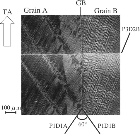
The appearance of slip bands was not uniform in Grain B. As presented in Fig. 7, in addition to the slip bands of the primary slip system P1D1B, slip bands on the P3 plane were activated close to the GB. This is accounted for by the relatively large stress transmission factor14)of 0.65 between
the primary slip system P1D1A in Grain A and the slip system P3D2B in Grain B, that is, the slip on the P3 plane in Grain B was induced by the activation of the primary slip system in Grain A.
Deformation bands can also be visualized with EBSP orientation imaging. In Fig. 8, orientation mapping obtained in the middle of the gauge length of Bicrystal 2 is presented. Orientation of each spot measured from the tensile axis was colored following the color coding shown in Fig. 8. There is a non-uniformly deformed region close to the GB in Grain B. In addition, the difference in the development of deformation bands in each grain is obvious from the orientation mapping. This is also found in theh100ipole figures constructed from the orientation data of the regions X and Y in the figure. The orientation variation in the region X of Grain A is larger than that in the region Y of Grain B. The region in Grain B close to the GB where P3 slip was activated (Fig. 7) is visualized in the orientation image in Fig. 8 as indicated by an elliptic mark.
3.3 Recrystallization of Bicrystal 1
As presented in Table 1, RGs were formed in Bicrystal 1 after the 2nd stage of annealing. A SEM image of the surface of Bicrystal 1 and its illustration showing the distribution of RGs are presented in Figs. 9(a) and (b), respectively. Twelve RGs were formed in Grain A in which deformation bands had been formed. Crystallographic orientation of RGs was measured and compared with that of the deformation matrix and the deformation bands in Grain A. We found that seven RGs had h111i rotation relationship with either of them (grayed in Fig. 9). The recrystallization behavior of Grain A
10
µ
m
50
µ
m
P1D1A
P2D2A
P2D2B
P1D1B
TA
(a)
(b)
Fig. 6 (a) Typical slip bands around a well-developed deformation band in Grain A of Bicrystal 2. (b) Slip bands around a deformation band in Grain B of Bicrystal 2.
100
µ
mTA
GB
Grain A
Grain B
60°
P1D1A P1D1B
P3D2B
[image:5.595.98.497.73.364.2] [image:5.595.49.288.421.651.2]agrees with that of aluminum single crystals tensile-deformed along theh110i direction to nominal tensile strain of 0.2 to 0.5. In those single crystals, RGs having h111i rotation relationship with the matrix or the deformation bands were formed along the boundaries between the matrix and the deformation band.
In Grain B, five RGs were formed. We found that four RGs hadh111irotation relationship with the orientation of Grain B (grayed in Fig. 9). The recrystallization in Grain B does not agree with the expectation deduced from the annealing behavior of aluminum single crystals tensile-deformed along the h100i direction at RT.12) In such h100i single crystals,
strain accumulation was very small due to the prominent cross-slip among eight almost equally activated slip systems. Deformation microstructure was characterized by coarse cells and low dislocation density at cell walls even after nominal tensile strain of 0.25 was applied to the crystals. As a result, no RG was formed. The discrepancy between the present result and the annealing behavior of h100i single crystals is probably attributable to the twist deformation of Grain A. As described in Section 3.1, the primary slip in Grain A produced twist about the normal to the GB plane. Such deformation was transmitted to the neighboring Grain B in a long range. We speculate that the twist deformation promoted the localized activation of minor slip systems with relatively small Schmid factors, which resulted in the formation of nuclei of RGs at the intersections of slip bands between primary slip systems and minor ones.15)
3.4 Recrystallization of Bicrystal 2
As presented in Table 1, Bicrystal 2 recrystallized after the 11th stage of annealing. An optical microscope image of the surface of Bicrystal 2 and its illustration showing the distribution of RGs are presented in Figs. 10(a) and (b), respectively. As expected from the development of deforma-tion bands, more RGs were formed in Grain A than in Grain B. Many RGs exhibited elongated shape along the deforma-tion bands. About half of the RGs had h111i rotation
relationship with the deformation bands or with the defor-mation matrix (grayed in Fig. 10). However, SIBM, common recrystallization behavior in bicrystals having a symmetric tilt GB did not occur. This will be discussed in the next section.
4. Discussion
In this section, mechanism of SIBM in bicrystals having a symmetric tilt GB is discussed and compared with the present experimental results in which no SIBM was observed.
Inoko et al.9,10) studied the recrystallization behavior of
tensile-deformed aluminum bicrystals in which the crystallo-graphic orientations of the component grains were symmetric about the GB plane and the Schmid factor of the primary slip systems in both grains were 0.5. The tilt angle between the component grains were 90 about a h211i axis. The edge
dislocations of the primary slip systems in both grains were parallel to the GB plane. Hence, the dislocations accumulated at the GB were edge dislocations. Deformation bands were formed symmetrically about the GB plane. When annealed, SIBM occurred. The original GB migrated from one grain into the other in some regions and vice versa in other regions. This mutually intrusive SIBM is explained by taking into account of the character of dislocations close to the GB and the deformation bands. As shown in Fig. 11(a), the sign of edge dislocations accumulated at the original GB is opposite to that of the edge dislocations accumulated at the left side (i.e. GB side) of the deformation band in Grain B. When annealed, these dislocations are attracted each other and annihilate. As a result, a region A0 having a similar
[image:6.595.311.545.75.303.2] [image:6.595.53.290.75.265.2]orientation to that of Grain A is formed in Grain B [Fig. 11(b)]. (Orientation of region A0 and Grain A is not always the same. In many cases, a sub-boundary P–Q is left at the position of the original GB between the region A0 and
500µm
TA
(a)
(b)
Fig. 9 Etched surface of Bicrystal 1 after annealing. A SEM image (a) and its sketch (b). In the sketch, recrystallized grains havingh111irotation relationship with the matrix are grayed.
1mm
TA
(a)
(b)
Fig. 10 Etched surface of Bicrystal 2 after annealing. An optical micro-graph (a) and its sketch (b). In the sketch, recrystallized grains having
Grain A.) Since the component grains are symmetric about the GB plane, the same mechanism is applicable to the SIBM from Grain B into Grain A.
In the present study, two types of bicrystals (Bicrystal 1 and 2) having an asymmetric tilt GB were used. In Bicrystal 1, the crystallographic orientations of the tensile direction were different for the component grains,i.e.h110iandh100i. From the stereographic projections of the initial orientation [Fig. 1(b)], it is apparent that dislocations accumulated at the GB from the primary slip systems did not have a large edge component. The predominant deformation transmitted through the GB was twist about the GB normal. As a result, no SIBM occurred and RGs were formed only throughh111i
rotation mechanism. In Bicrystal 2, as expected from the initial orientation (Fig. 2), dislocations of primary slip systems of both grains had a large edge component. Deformation bands were formed adjacent to the GB in Grain A. However, slip systems P3D2B was activated close to the GB in Grain B. Formation of deformation bands was suppressed in Grain B. Recrystallization occurred mainly along the deformation bands in Grain A and at the GB through h111i rotation mechanism. No SIBM was found.
Probably, typical SIBM is limited to bicrystals having a symmetric tilt boundary in which development of deforma-tion bands is symmetric about the GB.
5. Summary
Two types of aluminum bicrystals (Bicrystal 1 and 2) having an asymmetric tilt GB were tensile-deformed and subsequently annealed for recrystallization. Bicrystal 1 was composed of h100i{001} grain and h110i{001} grain. In addition to characteristic deformation for each component grain, twist of the h110i{001} grain induced the additional slip systems close to the GB in theh100i{001} grain. After annealing, most RGs were formed through h111i rotation mechanism. No SIBM was found. In Bicrystal 2, although the primary slip planes of the component grains were symmetric about the GB plane, the grain orientations were not symmetric. Deformation bands developed more in one of the grains than in the other grain. Additional slip was activated close to the GB. After annealing, RGs were formed at deformation bands and close to the GB. Similarly to Bicrystal 1, no SIBM was observed.
REFERENCES
1) H. W. F. Heller, C. A. Verbraak and B. H. Kolster: Acta Metall.32 (1984) 1395–1406.
2) W. B. Hutchinson: Acta Metall.37(1989) 1047–1056.
3) S. Kikuchi, E. Kimura and M. Koiwa: J. Mater. Sci.27(1992) 4927– 4934.
4) Y. L. Liu, H. Hu and N. Hansen: Acta Metall. Mater.43(1995) 2395– 2405.
5) M. C. Theyssier and J. H. Driver: Mater. Sci. Eng. A272(1999) 73–82. 6) K. Kashihara and F. Inoko: Acta Mater.49(2001) 3051–3061. 7) F. Inoko and G. Mima: Scr. Metall.21(1987) 1039–1044.
8) F. Inoko, T. Fujita and K. Akizono: Scr. Metall.21(1987) 1399–1404. 9) F. Inoko, M. Kobayashi and S. Kawaguchi: Scr. Metall.21(1987)
1405–1410.
10) F. Inoko and M. Kobayashi: J. de Physique Colloque C549(1988) 605–610.
11) K. Kashihara, M. Tagami and F. Inoko: Mater. Trans., JIM37(1996) 564–571.
12) M. Tagami, K. Kashihara, T. Okada and F. Inoko: Mater. Trans.42 (2001) 2013–2020.
13) F. Inoko, M. Kurimoto and K. Kashihara: J. Japan Inst. Metals 54 (1990) 642–649.
14) J. D. Livingston and B. Chalmers: Acta Metall.5(1957) 322–327. 15) T. Miyazaki, M. Tagami, T. Hama, H. Ogawa, T. Okada and F. Inoko:
J. Japan Inst. Metals68(2004) 342–349.
GB
Grain A Grain B Grain A Grain B
D.B.
Primary slip direct
ion
P
Q R A’ GB
Annealing
[image:7.595.48.289.68.285.2](a)
(b)
Fig. 11 Dislocation mechanism of the initial stage of typical strain induced boundary migration. Dislocations accumulated at the grain boundary (GB) and deformation band (DB) are annihilated to form a region A0having the