Abstract—In this paper the mechanical properties of carbon
nanotube C.N.T reinforced epoxy resin composite are studied with several methods in order to determine the best finite element modeling method. Composite effective module in different aspect ratios and volume fractions have been calculated. Effective ratio which achieved by different orientations of C.N.Ts in matrix has been investigated too. Two methods have been applied. In the first method by embedding a C.N.T into representative volume element with different alignments the equivalent module were calculated .In the second method, the nanotube was modeled as a beam element in a representative surface element. In both methods by substituting the obtained equivalent module in surface element, composite effective module has been calculated. Finally, the achieved results are compared with Halpin-Tsai method and also experimental results.
Index Terms—Carbon nanotube, finite elemen , resin.
I. INTRODUCTION
Carbon nanotube (C.N.T) has peculiar properties such as elastic modulus and high tensile strength. Both theoretical [1–4] and experimental [ 5–7] methods were applied in order to determine the Young’s modulus and Poisson’s ratio of C.N.Ts. Results were shown that it has quite broad variation of the Young’s modulus ranging from 200 to 4 TPa, tensile strength from 10 to 200 GPa, and bending strength of about 20 GPa [8–10] . Therefore it is one of the most promising materials with potential as an ultimate reinforcing material in nanocomposite [11-12]. Addition of C.N.T to matrix increases the toughness and stiffness and strength between composite layers. Addition of only 1% (by weight) C.N.T to matrix, can increase the stiffness of the matrix about 36%-46%. [13]. In order to calculate elastic properties of carbon nanotube composite some analytical methods such as role of mixtures and also Halpin-Tsai [15], Mori-Tanaka [14] relations has been applied. In the case of numerical methods, [16-19] has been used volume elements including C.N.T. Selmi, Friebel [20] has modeled twisted fibers of C.N.T by
Abdolhosein.fereidoon is Assistant professor Department of mechanical engineering semnan university .Iran (e-mail: [email protected] ).
Ssmaeel.saeedi is Master of Science student Department of mechanical engineering semnan university .Iran (e-mail: [email protected] ).
Babak.ahmadimoghadam is Master of Science student Department of mechanical engineering semnan university .Iran (e-mail:
[email protected] @yahoo.com).
numerical methods.
As the aspect ratio of C.N.T is very high and positions of them in matrix is randomly in many cases , so finding a good finite element modeling method which can mystery the nanotube condition in matrix and also has the most accordance with laboratorial conditions is very important .
In this study, the effective elastic modulus of the C.N.T filled nanocomposite is examined by using two finite element methods. Effects of aspect ratio and volume fraction and alignment of C.N.Ts on the elastic modulus are investigated.
Representative volume element by solid beam model and Representative volume element is adopted in this study to predict these effects. In order to compare the numerical results with analytic ones, the analytic model proposed by Halpin and Tsai [20] is employed. The numerically predicted axial tensile modulus is also verified by comparing it with experimental results.
II. METHOD A. Representative volume element
In model (a) similar to [16-20] has been used from a representative volume element that has a C.N.T inside of itself. The C.N.T dimensions are based on [17-18].
Dimensions of representative volume element were defined as follow:
3
L
V
=
(L)Element length = 120 (nm), (V) element volume The capability of C.N.T revolution in matrix was considered in dimensions.
Classic equivalent representative volume element module calculation method [21] was defined below.
Relation between stresses and strain for one transversely isotropic material can be written as follow.
(2)
Comparison Between Different Finite
Element Methods for Foreseeing the Elastic
Properties of Carbon nanotube Reinforced
Epoxy Resin Composite
Abdolhosein.Fereidoon, Esmaeel.Saeedi, and Babak .Ahmadimoghadam
⎥ ⎥ ⎥ ⎥ ⎥ ⎥ ⎥
⎦ ⎤
⎢ ⎢ ⎢ ⎢ ⎢ ⎢ ⎢
⎣ ⎡
− −
− −
− −
z z zx
z zx
z zx
x x xy
z zx
x xy
x
E E E
E E E
E E E
1 1 1
υ υ
υ υ
υ υ
⎪
⎭
⎪
⎬
⎫
⎪
⎩
⎪
⎨
⎧
z y x
σ
σ
σ
=
⎪
⎭
⎪
⎬
⎫
⎪
⎩
⎪
⎨
⎧
z y x
Fig. 1. Modeling the effective module of composite by representative volume element
4-independent constants (Young's modules Ex and Ey, Poison's ratios νxy and νxy) correspond to stresses and vertical strains. For calculating these 4 constants, we need 4 equations that will be obtained from using a simple load case along width and length directions of representative volume element.[17-18]. Fifth independent material constant- the shear modules Gxy can be obtained from using a simple (torsion) load case.
Finite Element for specifying the authority of this method and calculating effective elastic module has been used. For matrix modeling has been used from 8-node tetrahedral element and 20-node hexagonal for C.N.T modeling. Interface layer, elastic specifications of interface layer between C.N.T and matrix relevant to [22] has been equal to matrix specification.
Experiments show that in most cases, the C.N.T directions in matrix are completely random. Therefore, with isotropic assumption for resultant composite, instead of using equation (1), the effect of C.N.T different direction positioning in matrix was surveyed in 4 models.
In model a-1, C.N.T turned about
90
ο in a representative volume element with fixed dimensions and it's equivalent module was calculated. Fig. 1In model a-2 with fixing the representative volume element that due to volume fraction and fixing the C.N.T end distance from the representative volume element edges, C.N.T has turned about
90
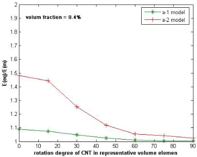
ο in matrix, also the dimensions of representative volume element was changed proportionally with the swiveling angle. Finally in 45 degree that has the largest area, has minimum thickness. Equivalent elastic module in different angles was calculated. Fig. 2. B. Calculating the effective elastic module [image:2.612.81.301.52.184.2]In models a-1 and a-2 for calculating the composite effective elastic module in C.N.T random distribution status in matrix, has been used a surface element. This element was divided to smaller elements and the elastic specifications of each surface were selected randomly from the results that achieved in models a-1 and a-2. In other words, surface element contains some parts that have C.N.Ts with random positions.
Fig. 2. Effect of C.N.T rotation in representative volume element. In (a-1) model volume fraction is equal to 0.4% and in (a-2) model, volume fraction is equal to 2.4 %
Eventually, load applied on surface element in plane stress status and the changing of element surface length was concluded and based on the (3), composite effective elastic module was obtained. (Table 1).
A
PL
E
eqδ
=
(3) Where (P) force on axial direction, (L) representative volume element length, (E
eq) equivalent module, (A) cross sectional area of representative volume elementTable. 1. results comparison in model a-1 , a-2 a-1 model a-2 model
m ef
E
E
1.03 1.13The main problem in these two modeling methods is to obtain the composite effective elastic module in different volume fractions. By this reason in b-1 and b-2 models respectively the sensitive rate of equivalent module of representative volume element in normal loading (zero angles) proportion to changing the element length and/or to changing in width of it has been calculated. Length and diameter of C.N.T was considered constant .Fig. 3.
[image:2.612.328.514.536.677.2]Fig. 4. Stress concentration in matrix around the two ends of C.N.T
As you can see, effective elastic module of representative volume element proportion to length changing is more sensitive than width changing, by this reason stress concentration is in matrix around the two ends of C.N.T, so by approaching the boundaries of representative volume element to the 2 ends of C.N.T up to 10(nm), the equivalent module value will increase approximately 4 times. Fig. 4. C. Representativesurfaceelement
In this method for calculating the effective module, representative surface element and C.N.T as beam element has been used. Applied elements for matrix are 8-node quadratic and for C.N.T modeling in matrix has been used beam element with hollow cross section with 10nm diameter and 0.4(nm) thickness [17-18].
Finally for modeling of C.N.T connection with matrix has been used beam elements
It is better note that the connection beams are used only for force transmission and displacement of C.N.Ts in matrix, so the connection beams are assumed completely rigid.
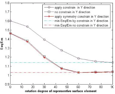
One of the major problems in nano scale modeling is applying the boundary conditions on the representative element. For surveying the effect of different boundary conditions on the results of composite equivalent module, 3 types of boundary conditions for top and bottom surfaces of representative surface element was defined.
(a) Top and bottom lines of representative surface element were constrained along y-axis.
(b) Bottom line of representative surface element has symmetry conditions.
(c) Top and bottom lines of representative surface element don't have any boundary conditions.
Results have been surveyed in different angle positioning of C.N.T. Fig. 5.
Equivalent module in first status of boundary conditions has so much deviation in angles of positioning between 15 and 75. Because the swiveling the representative surface element that happens by angular position of C.N.Ts in matrix.
[image:3.612.317.503.48.199.2]The most suitable type of boundary condition is fixing the top and bottom edges along Y direction that due to increase the equivalent module about 6%. Therefore, for modifying the results, they have to be subtracted 3% from equivalent module in first status. And after that the results can be used for calculating the element effective module.
Fig. 5. Boundary condition effects on equivalent module of representative surface element
Because the lengths of the representative surface elements was selected equally to the C.N.T lengths, for volume fraction and aspect ratio we can decrease the quantity of C.N.Ts in the matrix by reducing in representative volume surface. For minimum value, aspect ratio=25 and volume fraction=0.5, the minimum thickness for a C.N.T that can completely positioned inside the representative surface element is 78.53 (nm). In this model has been used from 100 nm thickness.
Also for low volume fraction and low matrix elastic module in proportion to C.N.T elastic module, we neglect from the beam interaction and matrix.
In this method has been assumed that C.N.Ts is in very small elements that aligned along the length of one C.N.T .Fig. 6.
A cod has developed in commercial FEM software ANSYS and The angle of C.N.Ts position in surface element has changed from zero to 90 degree and with applying loads the equivalent module has been calculated.
These operations for each angle have been repeating 5 times and equivalent elastic module in each status was obtained from the average of these 5 iterations.
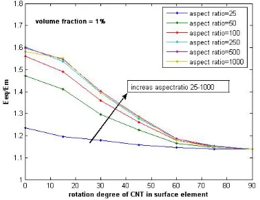
[image:3.612.88.276.48.183.2]The rate of equivalent elastic module for volume fraction in 1% and different angles for positioning can be seen in Fig. 7.
Figure 7. Rate of equivalent elastic module in different angles for positioning
[image:4.612.94.283.57.203.2]Fig. 8. Effect of changing the aspect ratio on effective module
Figure 9. Effect of changing the volume fraction on effective module
For calculating the effective composite module followed the section 2-2.Result was plotted. Fig. 8, 9.
As seen in the results, increase in aspect ratio greater than 250 in not effective to increase module.
D. Theoreticalmethods
The most common models used is (4) Halpin-Tsai equation [23–26]. The Halpin-Tsai equation for composites reinforced with randomly oriented C.N.Ts is given by [27]:
M CNT T CNT T CNT L CNT L CNT C E a E ⎥ ⎦ ⎤ ⎢ ⎣ ⎡ − + + − + = φ η φ η φ η φ η 1 2 1 8 5 1 2 1 8 3 NT M CNT M CNT L a E E E E 2 1 + ⎟⎟ ⎠ ⎞ ⎜⎜ ⎝ ⎛ − ⎟⎟ ⎠ ⎞ ⎜⎜ ⎝ ⎛ = η , 2 1 + ⎟⎟ ⎠ ⎞ ⎜⎜ ⎝ ⎛ − ⎟⎟ ⎠ ⎞ ⎜⎜ ⎝ ⎛ = M CNT M CNT T E E E E
η (4)
Where aCNT =(LCNT/dCNT) is the aspect ratio with CNT
L
being the length andd
CNT the diameter of the nanotubes,φ
NTis the C.N.T volume fraction andECNT, EM, and ECare the modulus of C.N.Ts, matrix, and composite, respectivelyIn align case Hlpin-Tsai relation written as:
⎟ ⎟ ⎠ ⎞ ⎜ ⎜ ⎝ ⎛ − + = f f m c V V E E η ζη 1
1 (5)
(
)
(
)
ζη − − = m f m f E E E E / 1
/ (6)
Where
V
f is volume fraction of C.N.T, andE
f and mE
are Young’s module of fiber and matrix respectively. The parameter ζ is dependent on the geometry and the boundary conditions of the reinforcing phase. For the case of aligned short-fiber composites, ζcan be expressed by:f
V
D
l
40
2
+
=
ζ
(7)For a low volume fraction (Vf ) the second term is negligible compared to the first term.
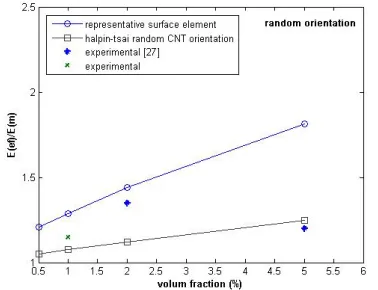
Effective elastic module in representative surface element module and Halpin-Tsai equation and experimental results in 1% volume fraction an`d different aspect ratios was compared with each other “fig. 9, 10”.
[image:4.612.90.287.239.389.2](b)
Fig. 9. (a),(b). Comparison between representative surface element results by experimental results and Halpin-Tsai formulation in variable aspect ratio
Figure10. Comparison between representative surface element results by experimental results and Halpin-Tsai formulation in variable volume fractions
III. RESULTANDCONCLUSION
As you can see in figure, representative surface element model shows good coverage with experimental results. Composite effective module with aspect ratios more than 250 doesn't show large increment but C.N.Ts aligning has so affects on composite effective module increment.
Results show that this model is useful for simulating the different types of short fibers in matrix but in C.N.T case for long length (in short C.N.T this value is minimum 500 (nm) usage of this type of modeling is unsuitable. In addition, in this modeling type fiber distance from the element edges and the distribution procedure is so significant.
In second model C.N.Ts positioned similar to beams in one representative surface element. C.N.Ts directions in element are aligned in different angle and the positioning places of them were random.
Results showed that this model for aspect ratios more than 50 has proper answers. More than that, achieved result range shows that representative surface element model is usable for large ranges of aspect ratios and volume fractions and results have proper coverage with experimental results.
For using of representative surface element model in low aspect ratios, needs more solutions and gets averages .Instead
of using volumetric element and beam, using from surface element and beam can give us more accurate results.
In third model for connecting beam elements to matrix have been used link and spring elements .But we should considering that insufficient DOF especially in 0 and 90 angles, achieved results have so many deviation.
REFERENCES
[1] Sanchez D, Artacho E and Soler J M 1999 Phys. Rev. B 59 12678 [2] Ruoff R S and Lorents D C 1995 Carbon 33 925
[3] Lu J P 1997 Phys. Rev. Lett. 79 1297
[4] Hernandez E, Goze C, Bernier P and Rubio A 1998 Phys. Rev. Lett. 80 4502
[5] Treacy M M J, Ebbesen T W and Gibson J M 1996 Nature 381 678 [6] Wong E W, Sheehan P E and Lieber C M 1997 Science 277 1971 [7] Yu M F, Files B S, Arepalli S and Ruoff R S 2000 Phys. Rev. Lett. 84
5552
[8] Wagner HD, Lourie O, Feldman Y, Tenne R. Appl Phys Lett 1998;72(2):188–90.
[9] Li F, Cheng HM, Bai S, Su G. Appl Phys Lett 2000;77(20):3161–3. [10] Lau KT, Chipara M, Ling HY, Hui D. Composites, Part B 2004;35:
95–101.
[11] Thostenson ET, Ren Z, Chou TW. Compos Sci Technol 2001;61: 1899–912.
[12] Lau KT, Hui D. Composites, Part B 2002;33:263–77.
[13] D. Qian, E.C. Dickey, R. Andrews, T. Rantell, Load transfer and deformation mechanisms in carbon nanotube– polystyrene composites, Applied Physics Letters 76 (2000) 2868–2870.
[14] Mori T and Tanaka K 1973 Acta Metall. 21 571 [15] Halpin J C 1969 J. Comp. Mater. 3 732
[16] BY N. HU 1 , H. FUKUNAGA 1 , C. LU 2 , M. KAMEYAMA 1, B. YAN 1. Prediction of elastic properties of carbon nanotube reinforced composites
[17] Y.J. Liu *, X.L. Chen. Evaluations of the effective material properties of carbon nanotube-based composites using a nanoscale representative volume element
[18] X.L. Chen, Y.J. Liu. Square representative volume elements for evaluating the effective material properties of carbon nanotube-based composites
[19] Young Seok Song, Jae Ryoun Youn . Modeling of effective elastic properties for polymer based carbon nanotube composites
[20] A. Selmi a, C. Friebel b, I. Doghri, H. Hassis. Prediction of the elastic properties of single walled carbon nanotube reinforced polymers: A comparative study of several micromechanical models
[21] M.W. Hyer, Stress Analysis of Fiber-Reinforced Composite Materials, first ed., McGraw-Hill, Boston, 1998.
[22] BY N. HU 1, H. FUKUNAGA 1, C. LU 2, M. KAMEYAMA 1 AND B. YAN1 Prediction of elastic properties of carbon nanotube reinforced composites
[23] Halpin, J. C.; Kardos, J. L. Polym. Eng. Sci. 1976, 16, 344–352. [24] Talreja, R.; Manson, J.-A. E. In Comprehensive Composite Materials,
Vol. 2: Polymer Matrix Composites, Kelly, A.; Zweben, C. H., Eds.; Elsevier Science Ltd., New York; 2000, p. 307.
[25] Cadek, M.; Coleman, J. N.; Barron, V.; et al. Appl. Phys. Lett. 2002, 81, 5123–5125.
[26] Halpin J. C, Tsai S. W, ‘Environmental factors in composite materials design’; US Air Force Technical Report AFML TR 67–423 (1967). [27] Richard P. Wool Carbon Nanotube Composites with Soybean Oil Resin
. chapter 14 Carbon Nanotube Composites with Soybean Oil Resins [28] Halpin, J. C.; Kardos, J. L. Polym. Eng. Sci. 1976, 16, 344–352. [29] Talreja, R.; Manson, J.-A. E. In Comprehensive Composite Materials,
Vol. 2: Polymer Matrix Composites, Kelly, A.; Zweben, C. H., Eds.; Elsevier Science Ltd., New York; 2000, p. 307.
[image:5.612.90.279.275.420.2]