Receiver based Rate Adaptation Approach through
Blind SNR Estimation of Satellite Channel
Sorum Kotia, Dr. K. S. Dasgupta and Dr. M. D. Desai
Abstract— A joint source and channel coding approach for image transmission over a satellite based broadcast channel is proposed. A resolution scalable source is matched to a hierarchical constellation in order to achieve an adaptive decoding capability. An estimate of signal to noise ratio (SNR) is derived blindly at the receiver and is used to facilitate reception at lower information rate. The rate is reduced by switching to a lower level constellation from hierarchical QAM. This ensures graceful degradation in performance and guarantees service with lower resolution for channel under-going high AWGN noise. The simulation results suggest that, for very noisy channels, the end to end distortion so obtained is much lesser compared to decoding at full resolution.
Keywords- Hierarchical (HR) mapping, Joint source and channel coding(JSCC), resolution scalability, , moment based signal to noise ratio estimation.,
I. INTRODUCTION
Reliable transmission of digital multimedia data over a noisy channel is a challenging task. It is especially difficult to guarantee a quality of service for band-limited satellite channels, which experience a large variation in channel noise. Primarily, it calls for a careful tradeoff between the throughput and quality of reception under the constraints of limited bandwidth and limited power. Secondly, it needs a mechanism to obtain channel state information (CSI) which could facilitate either adaptive transmission or adaptive reception under a varying link quality. A broadcast channel does not allow retransmission requests which could help mitigate data loss in poor channel conditions. Neither does it provide a dedicated link between transmitter and receiver which could help obtain information regarding link quality and hence provide adaptive throughput adjustment. Therefore, we suggest an approach which engineers resources at the transmitter to match a variety of channel conditions; derives an estimate of SNR at the receiver, uses these estimates to adapt the rate at the receiver and thus ensures service quality for satellite channels under broadcast scenarios.
Manuscript received on January 6, 2010.
Sorum Kotia is perusing PhD at EC Department of Nirma University Ahmedabad, India. She is presently working as a Faculty in the Electrical Engineering Department of The Maharaja Sayajirao University of Baroda, Baroda, India. (e-mail: [email protected]).
Dr. K. S. Dasgupta is the Deputy Director of SITAA,Space Application Center, Ahmedabad, India (e-mail:[email protected]).
Dr. M. D. Desai was a Faculty with EC Department, Nirma University, Ahmedabad, India. Presently he is working as a Professor with Kalol Institute of Technology, Kalol, India. (e-mail: [email protected]).
A combined source and channel coding scheme is investigated here for satellite based digital image broadcast, where the rate is adapted at the receiver using blind estimates of channel SNR. It is a static rate adaptation scheme for a satellite channel which is undergoing a large change in AWGN noise. The source coding technique and the error protection mechanism are loosely coupled to provide a suboptimal rate allocation, whereas adaptive reception assisted by blind SNR estimation at the receiver ensures guaranteed QoS and yet calls for a minimalist modification in the receiver.
The multimedia information, in this case an image, is described in a resolution scalable form. The hierarchy of source resolution is matched to a hierarchical (HR) modulation constellation. Such an integration of a multiresolution (MR) source coder and a HR constellation mapper facilitates a channel which virtually comprises of two embedded channels, each having unequal error protection (UEP). The information stream with stringent error sensitivities i.e. the coarser resolution is directed to the subchannel in a better condition. The less important stream i.e. finer resolution information is directed to the subchannel which is in a less perfect condition. UEP channels enable the receiver to decode the received signal with a resolution or quality which is in tune with the channel SNR. In good channel condition, the decoding is done at full resolution; whereas in poor channel condition the image is received with a reduced resolution. Similar MR-JSCC schemes for transmission over time-varying channels are discussed in [1]-[4]. However, in most of these cases, it is assumed that the CSI is available apriori and not much is said about how to obtain it.
The decision to reduce the rate by switching to a smaller constellation size is based on the estimated SNR values which are derived periodically from the baseband, sampled, data-bearing received signal. A relationship is established between the channel SNR and BER of HR signal constellation. It is used to justify selection of SNR as a performance measure for such hierarchically protected channels. The noise is assumed to be slowly varying and SNR estimation is done over a block of received samples. This block by block estimation averages out instantaneous channel fluctuations and provides a fairly stable rate adaptation process. The SNR estimation technique used in this paper is non-data-aided, implying a blind estimation scheme which is based on the moment based SNR estimation described in [5].
The outline of this paper follows here. Section II discusses the model describing the joint algorithm of mapping wavelet transformed image to HR constellation. In first part of Section III, a relationship between channel SNR and BER of HR constellation is derived and then follows the model for estimation of SNR. Simulation and evaluation methodologies are discussed in Section IV and Section V contains the results
II. REPRESENTATIVE MODEL FOR JSCC
A. Resolution scalable source
The term resolution scalability is defined as the ability to decode reduced-resolution versions of an image by decoding only the coarser coefficients from the desired resolution level. Here, the image is wavelet transformed and its each subband is individually quantized to obtain a two resolution scheme. Detailed procedure of the same is described in section IV. Wavelet transform is selected for its natural support for scalability and its capability of energy compaction. This two resolution source symbols are grouped into sequences with appropriate symbol length and is then provided with an unequal protection. This is achieved through HR mapping. A more reliable transmission channel i.e. a better error protection is applied to the coarser information. A nonuniform-PSK constellation is partitioned in such a way that the Euclidean distance of the most significant bits (MSB) is increased at the sacrifice of the least significant bits (LSB). The MSB define the four quadrants of the constellation, whereas the least significant bits are used to identify different modulation points within a quadrant.
B. UEP using Hierarchical (HR) mapper
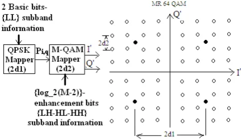
Hierarchical mapping can be seen as an M-bit mapping embedded in an N-bit mapping (N<M), thus making it an N+M bit mapper. Here, the coarser data bit sequence is represented by N bits/symboland finer resolution sequence is mapped as an M-bit/symbol. As a typical case, we employed HR mapping with M=4 and N=2 which is 4PSK/16-QAM mapping and is known as MR-64-QAM in literature. Every symbol in this hierarchical constellation is of 6 bits. The coarser resolution information is mapped on to the 2 MSB. The 4 LSB represent the finer resolution which is appended to the basic 4PSK constellation, giving it a hierarchical description. Thus, this HR constellation can be seen as a linear combination of two constellations of different sizes. The ratio of the intra-region
(satellite) mapping distance (2d2) and the inter-region (cloud) mapping distance (2d1) is denoted as parameter λ, which is held at a constant value.
[image:2.595.311.556.95.236.2]
Figure 1: 4PSK/M-QAM mapping arrangement and MR-64 QAM constellation
The outputs of both the mappers are represented as constellation vectors. The QPSK mapper output is represented as vector Pi,q = ±1±j which represents LL subband. The mapping vectors generated by LH, HL & HH subbands are denoted as Qi,q = ±i ± jq; where
i,q = 1,3, . . . , 2 1
2
2
M× N −. Pi,q & Qi,q are linearly combined to give I’ and Q’ as shown in Fig. 1.
The parameter λ is selected such that, the bit error rate of the coarser resolution channel is lower than that of the single resolution channel. However, the bit error rate of the finer resolution channel is higher. With such an arrangement, under equal transmission power, most of the bit errors are likely to occur in the least significant bits [6]. If uniform mapping were used, the errors are likely to occur with equal probability for all bits of the constellation symbol. For very noisy channel condition the constellation size is reduced from 4PSK/16-QAM to a 4PSK, i.e. more erroneous part of constellation is dropped and QoS is maintained with a reduced resolution.
III. A NOVEL APPROACH
A. BER as a function of channel SNR for HR constellation
Bit error rate (BER) is often used to assess the performance of digital systems under noise. We use the relationship between BER and channel SNR for a PSK constellation and derive a similar relationship for a HR constellation. We show that, the channel SNR is indicative of the quality of the link for hierarchical constellations as well.
The relation between BER and SNR for PSK symbols is given as [7, pg.338]
)
2
(
BT
SNR
Q
K
P
e=
⋅
symb⋅
ζ
A⋅
. (1)
Gaussian distribution, Q(x)= 0.5erfc(x/√2) and B is the
transmission bandwidth. SNR is the ratio of received signal power to noise power. A parameter of signal constellation is defined as,
2 2 min
2
2
/
a A
a
σ
ζ
=
; (2) where
a
min is minimum distance between signal constellation points and σa2 is the variance of the constellation points (assuming equi-probable constellation points ). Considering detection of an isolated pulse h(t), let the received signal beSkh(t). Sk is the PSK transmitted data symbol of the form described by (5). Output of the matched filter is Skσh2; where σh2 is the energy in the impulse response h(t) of the matched filter. Assuming no ISI, the received signal power is denoted as, Ps = σh2σa2 / Tsymb ; where Tsymb is the symbol period.
For a Hierarchical constellation, parameter ζA represents the ratio of the energy in the baseline 4-PSK constellation to the total average symbol energy [8]. In 4PSK-M-QAM constellation, separation between two cloud points is denoted as (2d1). Two satellite points are separated by a distance (2d2). This leads to the constellation parameter for HR constellation, written as
2
)
1
4
(
3
1
1
1
1 2
λ
ζ
λ−
+
=
=
M
d d HR
. (3)
It can be readily seen that for stand alone QPSK constellation, the parameter ζΗR reduces to the value 1. For a typical case of 4PSK-16QAM constellation, the constellation parameter is, ζΗR = (1+λ2)-1. Thus, the probability of error for hierarchically mapped symbols can be rewritten as
)
2
(
BT
SNR
Q
K
P
e=
⋅
symb⋅
ζ
HR⋅
. (4)
For a 16QAM constellation which is overriding a basic 4PSK constellation, the relative dimensions may change between the values 0< λ<0.5. Τhis implies that, the constellation parameter varies as 1<ζΗR <4/5. The same can be easily verified with the Nearest neighbors approximations for 16 QAM which is equal to
⎟⎟ ⎠ ⎞ ⎜⎜
⎝ ⎛
No Eb Q
5
4
.
These results establish that, for a fixed constellation parameter, channel SNR governs BER for HR constellations as well. Thus channel SNR can serve as a performance measure to suggest the quality of the link for HR constellations. If a mechanism is devised to estimate the channel SNR at baseband level, then an inference can be drawn for the quality of the link at the receiver itself. On the bases of these SNR estimates, a decision can be made to switch to a lower size constellation whenever channel quality degrades below a certain threshold value. This ensures graceful degradation in performance under adverse channel conditions.
B. Model for SNR estimation at Baseband
We consider a complex, discrete, baseequivalent, band-limited model (Fig. 2) of coherent M-ary PSK with a complex AWGN channel [5].
Figure: 2 Baseband equivalent system model
The SNR (
γ
) is defined as the ratio of the discrete signal power to discrete noise power at the input to the decision device at the optimal sampling instants. At the output of the matched filter, it is defined as the ratio of the symbol energy-to-noise power spectral density Es/No for complex channels. Perfect carrier and symbol timing recovery are assumed. The model is described in detail as given below.A block Nsym of the source symbols is upsampled to 4 samples per symbol, pulse-shaped by a root raised-cosine (RRC) filter (with rolloff =0.25 and 128 tap coefficients) with coefficients scaled to provide unity gain at DC. When transmitted through the channel the symbols are scaled by a constant attenuation factor, and are corrupted by sampled, complex AWGN. At the receiver the symbols are passed through a matched filter to obtain an estimate of SNR. The sequence of M -ary source symbols is represented by
)
(
2
n
e
s
j Mn
π
=
;
n
∈
{
0
,
1
,...,
N
sym−
1
}
(5)The intersymbol interference (ISI)-free output of the MF (the decision variable) is
n w n h
n
S
s
N
y
=
⋅
σ
2⋅
+
⋅
ω
2
; (6)
where, S is the signal power scale factor and Nw is the noise power scale factor. For the sampled yn to be the decision variable, the actual SNR may be written as
}
var{
}
2
{
2 2 h
n w
n
w
N
s
S
E
⋅
⋅
⋅
=
σ
γ
(7)2 2 4
}
{
}
{
n n ss
E
s
E
k
=
&2 2 4
}
{
}
{
n n ww
E
w
E
k
=
; (8)are the kurtosis of signal and kurtosis of noise, respectively.
The estimated SNR is
γ
ˆ
=
S
ˆ
/
N
ˆ
; where4
)
4
(
4
2
)
4
(
)
2
(
2
ˆ
2−
+
−
+
+
−
±
−
=
w s w s w s wk
k
k
k
M
M
k
k
k
M
S
, (9)
S
M
N
ˆ
w=
2
−
ˆ
. (10)
10 0 2 4 6 8 10 12 14 16 18 20
-3
10-2 10-1 100 101
m r c
[image:4.595.41.286.53.377.2]Eb/No (dB)
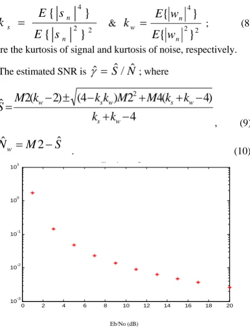
Figure 3: Normalized MSE of M2M4 estimation derived for complex AWGN channel; NMSE v/s Eb/No (dB)
This estimator does not require carrier phase recovery. It is a moments-based estimation technique hence it does not even use the receiver decisions for estimation. The normalized MSE for an unbiased SNR estimator in a complex AWGN
channel is expressed as
2 ) ˆ ( ) ˆ ( γ γ γ MSE NMSE = ;
where
γ
ˆ
is the estimated SNR andγ
is the true SNR value. The plot of NMSE v/s Eb/No (dB) is given in Fig. 3. The estimation was performed for the block length of 128 symbols and the normalised MSE was plotted over 10 iterations. Estimation accuracy improves with longer block length and with estimation over more number of iterations [5].IV. SIMULATION AND EVALUATION METHODOLOGY
A. Simulation
An embedded representation of the image is obtained using wavelet transforms. A single level, 2-D wavelet transform (Daubechies filter – D4 variant) is obtained for a P x P image. The four matrices of size P/2 x P/2 coefficients are arranged to get two different resolutions. The transformed and normalized coefficients are grouped into two vectors; each representing one resolution. The approximation coefficients of LL subband make coarser resolution, and detail coefficients constituting horizontal (HL), vertical (LH) & diagonal (HH) subbands are clubbed together to make finer resolution. Thus a twin class
system is obtained; the coarser resolution is HP (high protection) class and the finer resolution make LP (low protection) class.
Next, the transformed, two resolution image is quantized. Quantization process is the principle cause of data loss in this entire process of MR source coding. Although the LL subband makes the coarser scale, it is quantized with finest step size. This smallest stepsize contributes mininjmum quantization noise to the approximate coefficients. The detailed coefficients of the HH subband are also quantized with same step size, while the quantizers for other two bands (HL, LH) have relatively larger stepsize. This variation in stepsize of quantizers for different subbands, gets the transformed image to form a multiresolution source. The manipulation of the quantizers’ step-size also makes the length of data vector for the two resolutions equal. The compression so achieved due to differential quantization stepsize is 4:3. Due to this suboptimal compression, the quantized image contains residual redundancies that can be further compressed using an appropriate encoder-decoder pair. However in this case, a separate encoder is not used. The quantized bits are converted into appropriate symbols and are directly mapped to individual constellations, depending on the class they belong to. The quantized bits for both HP and LP streams are grouped into symbol sequences, where HP is grouped into 2 bits/symbol & mapped to basic QPSK constellation; whereas, LP is grouped into log2M bits/symbol & mapped to M-QAM constellation. Passband noise is simulated at baseband by appropriately converting Eb/No to SNR and the end to end distortion for the reproduced image is obtained. Simulation is carried out with MATLAB version 8.0.
B. Evaluation methodology
A performance measure is selected such that, it reflects tradeoff effects for the combined source-channel-coding problem. Hence the performance is evaluated using a relation between end-to-end distortion and channel SNR. It is denoted here as the ‘MSD- SNR curve’. The mean value of squared error (MSD) between the original image and the reconstructed image is evaluated at various Eb/No values. This is analogous to the distortion-rate (D-R) function which is used in evaluating performance of a source coder. The major contributors in this end-to-end distortion are namely, the quantization distortion, effect of modulation noise due to HR mapping and the effect of AWGN channel. The wavelet transformation is considered to be a perfectly reversible process. However, a cause of data loss could be attributed to the floating-point rounding-off errors, which occur while calculating forward and inverse transformations with non-integer wavelets. This distortions are described individually as given below.
i) The quantization distortion: Finding the nearest reproduction vector Ciof the source vector C is equivalent to finding a vector that minimizes a distortion measure. Here, the Euclidean distance measures the distortion between C and Ci:
∑
=−
=
l k ii
c
k
c
k
c
c
d
1 2)
(
ˆ
)
(
)
ˆ
,
(
quantizer is directly mapped to one of the signal points in the constellation. Average mapping distortion is minimized if the two sets are compatible i.e. a quantization level corresponds to a modulation level. This one to one correspondence provides very good protection against transmission errors when used with high spectrally efficient modulations. The robustness tends to decrease when we reduce the number of states of the modulation and map more than one quantization levels to one modulation level [9].
ii) Distortion due to HR mapping: Performance
degradation is observed by a QPSK receiver when it is receiving a hierarchical constellation. This distortion is an inherent feature of any HR mapper and its mathematical model is developed in [10]. For the present discussion, let the ratio Es/No be called the carrier to noise ratio (CNR) of the hierarchical constellation, which is denoted as,
No
d
No
Es
CNR
2 1 2
)
1
(
2
+
λ
=
=
. (12)
The basic QPSK constellation power is (2d12). The power of the QAM constellation which is overriding 4PSK is given as (2d12λ 2). When an HR constellation is received by a basic QPSK receiver, the secondary constellation is perceived as an additional noise (other than channel noise No). Effect of this scattering of points due to secondary constellation is quantified as the modulation noise ratio (MNR). The modulation noise ratio is defined in [10] as the ratio of the power of QPSK constellation to the combined noise power, and it is given by
2 1 2 2 1
2
2
d
No
d
MNR
λ
+
=
. (13)
MNR can be considered as the CNR of the hierarchical constellation as viewed by the QPSK receivers. It is the degradation observed by a basic QPSK receiver due to additional secondary information. It can be evaluated by comparing the values of CNR and MNR. The difference between MNR and CNR is the penalty to the QPSK receivers. The penalty in MNR can be defined as the ratio CNR/MNR.
)
1
(
1
2CNR
MNR
CNR
P
MNR=
=
+
λ
+
(14)
This is the distortion added in reproduction of coarser resolution compared to its transmission as a pure QPSK constellation. Equation (14) suggests that, this penalty is a function of both λ and CNR. For 0 <λ <0.5, PMNR varies between 1 to (1.25+CNR/4), i.e. the penalty is higher at higher CNR. However, this penalty does not have a significant impact, as most of the satellite broadcast systems such as satellite radio, or satellite TV operate with enough margins in the CNR to meet the desired performance.
iii) Channel induced distortion: BER for a given channel SNR is discussed in section III; which reflects the contribution of AWGN noise in the distortion observed in image reconstruction. Contribution of all the three distortions
discussed above has been considered comprehensively in calculation of MSD.
V. RESULTS AND DISCUSSION
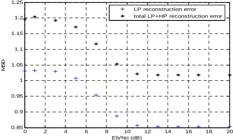
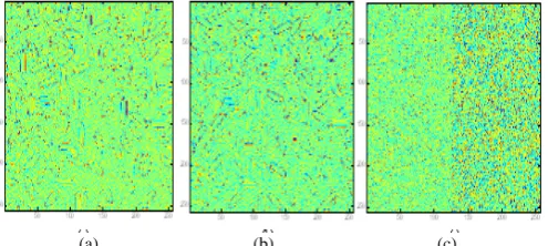
MSD-SNR curves for both coarse and fine resolutions are plotted for various values of Eb/No measured in dB. As observed in Fig. 4 and Fig. 5, the distortion due to channel noise is more pronounced for secondary information which is mapped to the QAM constellation. There is substantial difference in absolute values of MSD for LL subband (HP class) and LP class (fig.4) for lower values of Eb/No. This is in tune with BER curves discussed in [6] & [11] for hierarchical constellations. The results show that end to end distortion (represented as MSD) is the least for reproduction of LL subband. Fig.6 shows the how the reconstructed image will look like if the finer resolution is not used in reconstruction of a 256 x 256 size rice.png image. Fig. 6(a) shows the distortion only due to wavelet transformation. As the transformation process is perfectly reversible, it produces a negligible distortion. Thus Fig 6(a) can be taken as a reference image. Fig.6(c) shows LL subband reproduced with 10dB Eb/No introduced in the channel. It shows slight deterioration from the image which is reproduced through a channel without AWGN noise source (Fig.6 (b)). Fig 6(b) shows distortion due to the process of quantization and hierarchical mapping.
The finer resolution image is made up of Horizontal, Vertical & Diagonal wavelet components and is reproduced as shown in fig (7). This is the information content which dropped in poor SNR conditions. Fig. 7(a) shows distortion merely due to - wavelet transformation, Fig. 7(b) presents combined distortion due to all the three component viz. discrete wavelet transform (DWT), quantization and HR mapping. Fig. 7(c) shows end to end distortion, including the effect of channel noise for LP class. Comparison of fig 6(c) and fig 7(c) reveals that the selected value of λ induces more distortion for LP class for a given value of Eb/No. Satellite to cloud ratio is selected such that impact of channel noise is more prominent for LP class information which is mapped to satellite points. Under adverse channel condition this more corrupt part of constellation is dropped and the service is provided at coarser resolution.
0 2 4 6 8 10 12 14 16 18 20
0.85 0.9 0.95 1 1.05 1.1 1.15 1.2 1.25
Eb/No (dB)
MS
D
LP reconstruction error total LP+HP reconstruction error
[image:5.595.312.552.522.666.2]0 2 4 6 8 10 12 14 16 18 20 0.165
0.166 0.167 0.168 0.169 0.17 0.171 0.172 0.173
Eb/No (dB)
MS
[image:6.595.52.273.56.185.2]D
Figure 5: Reproduction error showing end to end distortion for HP class (mapped to QPSK) for various values of Eb/No(dB)
[image:6.595.42.281.218.335.2](a) (b) (c)
Figure 6: Reconstruction of LL subband: (a) immediately after DWT (corruption due to only transformation); (b) with channel containing no noise (corruption due to DWT, quantizer amd mapper), (c) after transmission through channel with 10 dB Eb/No
(a) (b) (c)
Figure 7: Reconstruction of Finer resolution (LH-HL-HH subbands): (a) immediately after DWT; (b) with channel containing no noise (corruption due to DWT, quantizer amd mapper), (c) after transmission through channel with 10 dB Eb/No
VI. CONCLUSION &FUTURE SCOPE
For satellite based image transmission, the proposed scheme adapts the information rate on the basis of SNR estimation at the receiver. It provides service at various resolution levels over large variation in channel noise. The scheme discussed above uses a joint source and channel coding approach which maps a muliresolution source to HR constellation and achieves desired resolution scalability. This provides the image, an adaptive robustness against fluctuating channel conditions.
The scheme is particularly relevant for broadcast over satellite channels where both transmitter and receiver are blind
to the channel statistics. The decision to drop off QAM constellation overriding a basic QPSK constellation is based on the SNR estimation which is derived using kurtosis of signal and kurtosis of noise. The results indicate that there is a benefit of using this scheme which performs blind SNR estimation in order adapt information rate at the receiver.
Though in this paper, we have considered only two level modulation (viz. QAM & QPSK), the scheme can be extended to other digital modulations in order to obtain a multi-level model. A finer granularity in scalability can be achieved by extending it for a source embedded into more than two resolutions. The extension of present scheme for various fading channels is also being investigated. Additionally, the performance can be enhanced by using various channel coding techniques along with hierarchical mapping which may provide a certain coding gain.
ACKNOWLEDGMENT
I sincerely thank Mrs. Saumi De (Sci/Engr.SF, ADCTG, ISRO, Ahmedabed), for her valuable suggestions throughout the development and continual support in reviewing this paper.
REFERENCES
[1] K. Ramchandran, K. M. U. A. Ortega, and M. Vetterli,” Multiresolution broadcast for digital HDTV using joint source/channel coding”, IEEE Journal on Selected Areas in Communications, vol. 11, pp. 6–23, Jan. 1993.
[2] T . Cover, “Broadcast channels,” IEEE Transactions on Information Theory, vol. IT-18, pp. 2–14, Jan. 1972.
[3] S. Zahir Azami, P. Duhamel, and O. Rioul. “Joint source-channel coding: Panorama of methods”. CNES Workshop on Data Compression, Toulouse, France, November 1996.
[4] Igor Kozintsev,Kannan Ramchandran, “Robust Image Transmission Over Energy-Constrained Time-Varying Channels Using Multiresolution Joint Source–Channel Coding”, IEEE Trans.Signal Procs.,vol. 46,no. 4, April 1998.
[5] David R. Pauluzzi and Norman C. Beaulieu, ”A Comparison of SNR Estimation Techniques for the AWGN Channel” - IEEE Transactions on communications, VOL. 48, NO. 10, OCTOBER 2000.
[6] Pavan K. Vitthaladevuni, and Mohamed-Slim Alouini, “Exact BER Computation of Generalized Hierarchical PSK Constellations”, IEEE International Conference on Communications (ICC’2002),NewYork, April 2002.
[7] Edward A.Lee,David G.Messerschmitt, “Digital Communication”, second edition, Allied Publishers Limited, Kulwer Academic Publishers,1996.
[8] Pavan K. Vitthaladevuni, and Mohamed-Slim Alouini, “BER Computation of 4-M-QAM Hierarchical Constellations”, IEEE Transactions on Brodcasting, vol. 47, NO. 3, SEPTEMBER 2001 [9] Yun Li, Anthony Ephermides,”Simple rate control for Fluctuating
channels in Ad-hoc wireless networks”, IEEE Transactions on Communication,vol.53,No.7,july 2005
[10] Hong Jiang, Paul A. Wildrof, “A hierarchical modulation for upgrading digital broadcast system ”, IEEE transactions on broadcasting, vol 51,No.2,June 2005
[11] Alouini, M-S, Tang, X, Goldsmith, A.,” An adaptive modulation scheme for simultaneous voice and data transmission over fading channels”.
[image:6.595.39.287.388.499.2]