Available from Sheffield Hallam University Research Archive (SHURA) at:
http://shura.shu.ac.uk/24838/
This document is the author deposited version. You are advised to consult the
publisher's version if you wish to cite from it.
Published version
GHOSH, Ayan, PENDERS, Jacques and SORANZO, Alessandro (2020). Haptic
directional information for spatial exploration. In: 2019 28th IEEE International
Conference on Robot and Human Interactive Communication (RO-MAN). IEEE.
Copyright and re-use policy
See
http://shura.shu.ac.uk/information.html
Abstract— This paper investigates the efficacy of a tactile and
haptic human robot interface developed and trialled to aid navigation in poor visibility and audibility conditions, which occur, for example, in e.g. search and rescue. The new developed interface generates haptic directional information that will support human navigation when other senses are not or only partially accessible. The central question of this paper was whether humans are able to interpret haptic signals as denoting different spatial directions. The effectiveness of the haptic signals was measured in a novel experimental set up. Participants were given a stick (replicating the robot interface) and asked to reproduce the specific spatial information denoted by each of the haptic signals. The task performance was examined quantitatively and results show that the haptic signals can denote distinguishable spatial directions, supporting the hypothesis that tactile and haptic information can be effectively used to aid human navigation. Implications for robotics application of the newly developed interface are discussed.
I. INTRODUCTION
Robots could be useful aids for humans navigating in low visibility as previous research has shown by exploring the searching activity of firefighters in smoke-filled environments [1]. However, not much attention has been given to the human robot interaction in such circumstances that is in the absence of visual (because of the smoke) and aural feedback (because of the noise). The authors of [2] reported the application of a physical handle - a stick modelled as a crutch - to link the robot to the human. They distinguished between navigation and locomotion guidance: navigation involves wayfinding while locomotion guidance denotes traversing from the current location to the nearest waypoint [2]; locomotion guidance by a robot has been investigated and reported in [3]. Robots are helpful for navigation as the localisation problems are technically solved [4]. However, autonomous mapping of a smoke-filled environment is not reliable: conventional light based sensors (including lasers) are severely hampered by smoke and ultrasound sensors are hampered by the noise caused by fire [1]. Thus in order not to bump into objects the human still has to supervise the robot when exploring the surroundings. Exploring an environment in low visibility with a robot is still challenging. When navigating (and exploring) in normal conditions the visual sense provides an overview of the surroundings. However, in non-visibility conditions, a representation of the environment has to be formed on the basis of information from other senses. Visually impaired people face these challenges and they rely mostly on auditory
* Research was supported by the UK Engineering and Physical Sciences Research Council (EPSRC) grant no. EP/I028765/1.
Ayan Ghosh is a post-doctoral researcher with the University of Sheffield. (email: [email protected])
information partly compensating for the absence of visual information [5].
Works concerning assistive technology for the visually impaired are relevant for our application; however, there are some important differences. The robotic shopping trolley developed by Kulyukin [6] and [7] guides the visually impaired shopper - who is holding the trolley handle - along the aisles into the vicinity of the desired product. The locomotion guidance is fully robot driven but restricted to passing through the aisles; the emphasis is on instructing the shopper how to grab the product using voice instructions. But in search and rescue operations, such as those that firefighters have to face, auditory information [8] and voice feedback [9], [10] are ruled out.
Exploring the environment with a semi-autonomous robotic aid and advancing forward involves mental tracing of the path and locations of objects in the immediate environment. How people mentally store spatial information is still subject of discussion as we briefly discuss below. Nevertheless, the main task for the human-robot interface designer is to provide cues to enable the human being to build the spatial representation. Inspiring for the design used in this project have been observations concerning guide dogs [2]; in line with guide dog practices, we will call the human being handling the stick the 'handler'.
The interface has to enable the handler to explore the surroundings: it has to provide the handler with control over the robot as well as meaningful feedback. A technical design of such a device, is given in [13], in essence it is a joystick like device mounted on the handle; the joystick controls the actions of the robot. While exploring the surroundings using the robot as a 'cane', the robot will hit obstacles, for this purpose a bumper or impedance filter is mounted on the robot, refer to Fig. 1. The robot is a powered device and the handler may feel that the robot slows down when hitting some obstacle, but that does not provide feedback as to where the bumper has hit the obstacle. In the current design the displacement of the bumper is fed back to the handler, it basically indicates the angle of the point of impact, thus informing the handler of the direction to the obstacle. The overall aim of the current paper is to explore by experimentation the effectiveness of the haptic signals in providing directional information. Positive results will enhance the assumed potential of a robotic aid to contribute to spatial exploration and justify the engineering effort to further develop the device.
Jacques Penders is a Professor at Sheffield Hallam University and deputy director of Sheffield Robotics (email:[email protected])
Alessandro Soranzo is a Reader in Psychology, at Sheffield Hallam University, Sheffield UK; email: [email protected].
Ro-Man2019 Haptic Directional Information for Spatial
Exploration *
The paper is organised as follows. Section II briefly describes the robot and the human robot interface. Section III touches on spatial cognition. Section IV describes our experimental set up to test the effectivity of the set of haptic signals, while section V outlines the results. The paper finishes with conclusions.
II. ROBOT AND INTERFACE
[image:3.595.342.534.221.338.2]The work reported in here builds on the Reins project [2], which developed and trialled tactile and haptic human robot interaction for application in low visibility and poor audibility conditions, as is typical for firefighting. The project applied a crutch-like stick to link the human and the Pioneer-3AT 4-wheel robot, refer to Fig. 1, left and middle.
Figure 1, left: the guiding robot with handle; middle: handle right bumper.
Obviously, to be able to follow the robot, the handler needs to know where the robot is, relative to his/her current position and orientation. In [3] it is argued that a stiff handle is the best solution for enabling the handler to know where the robot is relative to the handler's position: distance (length of the stick) and orientation (direction of the stick) are implicitly given. However, [3] also notices a lack of accuracy in sensing the direction when holding a stick blind folded, and concludes that a crutch like design fixed on the lower arm, is preferred. The handle is attached to the robot with a flexible joint (spring system) and aligned with the center line of the robot, refer to Fig.1 left. The handle can rotate in the horizontal plane, and rotation induces tension on the handle; this induces the best robot following behaviour as [3] has shown.
A. Robot and Bumper
In [1] it is shown that light based sensors (including lasers) are severely hampered by smoke and ultrasound sensors are hampered by noise. Therefore, a bumper was designed allowing the robot to bump into objects, the collision point (point of impact) is relevant for navigation and fed back to the human handler via a handcuff.
The design of the bumper mechanism or impedance filter is shown in Fig. 1, right; it consists of an inner platform suspended by springs which are connected to the outer bumper. The prototype bumper covers the whole robot, while the handle is to be fixed above the bumper. The displacement of the bumper with respect to the centre of the robot is measured by Cable Reel Transducers (CRTs). When colliding with an obstacle the displacement of the bumper indicates the point of impact. The direction to this point is fed back to handler via the feedback cuff. Fig. 1, middle shows the fixation points for the feedback cuff.
B. Feedback provision
The cuff for feedback from the bumper to the handler sits on the lower arm of the handler. It is fitted with Lilypads
vibrating motors which vibrate for a short time period (1 second). Following the observations of [14] two sets of 2 motors are applied, ref to Fig. 2, they provide the basis for an alphabet of four separate digits corresponding with each motor being activated separately. In addition also combined activations can be thought of. However, [3] found that subjects tend to perceive this as a single, more intense, signal.
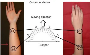
Figure 2, Two sets of two vibration motors; left: attached to the inner side of the right arm; right: attached to the outer side, middle: the points of impact (A,B,C,D) on the bumper and the correspondence with the vibration motors.
When a handler is navigating an environment, certainly when unknown, new data/information about the area in front is the most relevant. Data about the area behind has already been collected in previous steps and up-dates are relatively unimportant. Following this reasoning we focus on representing data about the front half of the robot bumper in the heading direction. Moreover, since we have an alphabet of four signals (the four vibration motors, L1, R1, L2 and R2 in Fig. 2), we can assign four points to the bumper: points A-D in Fig. 3. Where an outstretched arm is used to indicate direction, the hand end symbolises the far end; we thus assume it is most intuitive to associate the front points A and B on the bumper with vibration motors L1 and R1 in Fig. 3. When holding the handle as in Fig. 1, with the right hand stretched naturally with the thumb up, the inside of the forearm is on the left while the outside is on the right, thus motors L1 and L2 are associated with left and R1 and R2 with right. For a left-handed person L1 and L2 sit on the outside of the forearm while R1 and R2 on the inside.
III. SPATIAL COGNITION
How humans represent spatial data in memory is still a subject of discussion within psychology. Central in the discussions is the distinction made by Klatsky [10] between an
egocentric representation (a coordinate system centred on the navigator) and an allocentric representation (a coordinate system located and oriented on the environment), refer to [11] or [12]. For scene recognition, the egocentric system is the most important, whilst for navigation and orientation the allocentric system is dominant [12]. The spatial tasks that are intensely studied in this context are: recognising scenes, reorienting and updating [15]. The discussions focus on whether both types (egocentric and allocentric) are needed for a particular task and whether these different types of representations combine in human memory. Burgess [16] developed a two system model of parallel egocentric and
[image:3.595.57.302.264.384.2]argued that navigation could be a translation between both systems.
However, when the environment is unknown and there is no visual or audible information, the allocentric spatial representation is missing. In order to make prompt navigation decisions, the handler needs some mental representation or mental map of the close surroundings, which is egocentric in nature and gets updated continuously. Wang and Spelke [17] argue that the representation of targets is relative to self and is updated as the navigator moves through a novel environment. In the process, a cognitive map develops which accounts for the locomotion along the path. Studies in cognitive psychology report that humans can form images of unseen environments; the images are egocentric, representing the environment from a particular point of view.
Amorim et al. [17] demonstrate that humans have two different types of processing modes in their memory during non-visual navigation: a task centered and an object centered processing mode. In object centered mode the object's perspective is kept track of at every instance of the navigation thereby making it challenging in terms of cognitive load. The object centered mode involves slower body movements and locomotion. In task centered mode, a human being is mentally tracing the path without worrying about the objects. Thus we distinguish exploration (object centered) from navigation (task centered). The processing modes are a prerequisite for path integration [18] which uses available vestibular and kinesthetic information to maintain self-orientation and position during navigation in the absence of vision.
In [3] an experiment is described with blindfolded participants being guided by a robot along a variety of short trajectories with a sharp (about 70°) or a gentle turn (about 45°). After completing a trajectory, participants were asked which trajectory they believed to have followed by choosing from a set of pictures. The subjects were mostly accurate in determining whether the turn was a left or a right turn; however they were less accurate in distinguishing between a sharp and a gentle turn [3]. This indicates that attempting to show directly that the robot is an effective aid for wayfinding in non-visibility conditions may be over ambitious. The robot device generates haptic directional information. This paper focusses on how well haptic directional information is represented in a person's spatial memory. Positive results will show the potential contribution of a robotic aid to spatial exploration.
IV. SET UP OF THE EXPERIMENT
As discussed above, the object centered processing mode is demanding, it is therefore important to design a simple experiment to see whether on receiving a haptic signal (vibrating motor activation) a handler is able to point out the particular direction in space. Our experiment is an adaptation from the work of Gescheider [20] who compared localisation of a sound based on either acoustic or cutaneous feedback. Another aspect of our experiment is inspired by Haber et al. [21] who stated that pointing methods using body parts (e.g., nose, chest, or index finger) or extensions of body parts (e.g., a hand-held cane) lead to a more accurate response; our handle complies with the experimental prerequisites.
A. Apparatus
As explained in Section II, the reins project used a crutch like the handle; in our experiments a wooden replica is used. Similar to its original, the replica handle has a crutch like design and is strapped to the lower arm of the handler; the replica is 1.2 meters in length, from the point of hold to the tip. The vibrating motors are attached to the forearm of the participants, as shown in Fig. 2. The motors are connected through a National Instrument DAQ card and activated using a software interface developed in NI-Labview 2009. The motors are individually controlled by the operator; all motors are activated for a period of one second and all operate at the same frequency and intensity.
On the activation of a motor, participants will be asked to indicate with the handle the associated impact points on the bumper (points A-D in Fig. 2). To create a spatial presentation, a semi-circle with a radius of 1.7 meters is drawn on the floor within which the target areas (in red) are marked out (refer to Fig. 3). The target areas correspond to the impact points on the bumper as follows:
Target Area 0: perpendicular to the base of the half circle; Target Area A: 67.5°, which is left of the middle;
Target Area B: 112.5°, which is right of the middle; Target Area C: 22.5°, which is further to the left; Target Area D: 157.5°, which is further to the right.
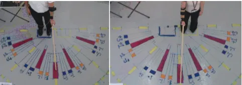
Nine marks were drawn between each of the Target Areas to enable precise scoring of the errors in the participants' performance. Footprints were marked 20 centimeters on the either side of the centre line through Target Area 0 (for left and right handed participants) to ensured that the handle would naturally align with the centre line through Target Area 0, refer to Fig 3, left and right. The participants were asked to stand on the footprints, in order to make sure that their feet position and body orientation remains the same throughout. As discussed above, the images humans have of unseen environments are egocentric; therefore a nearly fixed body orientation is important.
B. Scoring
[image:4.595.318.559.613.698.2]The trials were video recorded with a camera mounted on the ceiling; it provided a view on the experimental area as shown in Figs. 3 and 5. The recordings were used for error scoring; since the camera provided an orthogonal projection of the handle on the floor, distortion was minimal.
Figure 3 The experimental layout, a protractor painted on the floor as well as a marked position for the participant, left: left-handed, right: right-handed participant both at start positions.
an overshoot anticlockwise was coded as negative. Hence, the error scores measure inaccuracies: the higher the absolute error score, the less accurate the subject was.
Participants were asked to move the handle to a particular target area in reaction to signals from the vibration motors; they started from a resting position, tick on the target area and return to the resting position. However, the resting positions would not always coincide with the centre line through Target Area 0, Fig. 5 shows examples. The question arises whether the participants interpret the target areas as being relative to their own body position or to the current resting position. Inspired by [24] two different error scores were given for each trial, the 'original score' as explained above and a 'relative score'. The resting position of the handle - before each particular motor activation - was scored relative to Target Area 0, as before by counting the markings overshot. The relative error score was calculated by subtracting the rest position score from the original error score. Thus we were able to evaluate whether the initial resting position had impact on a participant's performance.
C. Protocol
Nine participants, 4 females and 5 males, aging between 22 and 55 without any medical condition, took part in the study. They were given a briefing about the experiment and asked to sign a consent form and then asked to stand in front of the semi-circle and hold the handle allowing the experimenter to assess left or right handedness. Disposable stockings were provided to wear on the lower arm - if they wanted - for hygiene reasons.
Each participant undertook 6 trials. The trials are carried out in both non-blindfolded and blindfolded states.
[image:5.595.329.536.103.189.2]The first set (referred to as trial 0) was a Pre-Test intended to measure participants' spontaneous interpretation of the notions of small and large movements (without explanations about the target areas). Participants were blind-folded and asked to hold the handle and carry out the following instructions: a small movement of the handle to the near left (given a gentle tap on the left shoulder - to avoid verbal left/right confusions); a small movement of the handle to near right (given a gentle tap on the right shoulder); a large movement of the handle to the far left (given a gentle tap on the left shoulder); a large movement of the handle to the far right (given a gentle tap on the right shoulder)
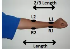
Figure 4, Instruction sheet for positioning the vibrating motors on the arm.
The next set of trials (trials 1 to 5) used the same experimental layout; but participants had to wear the vibration motors. In order to make sure that the vibration motors (L1, L2, R1, R2), were fitted uniformly for all participants, we measured the lengths between wrist (carpus) and elbow (olecranon). L1 and R1 sit on the carpus whereas L2 and R2 sit on the part of the lower arm that corresponds to the two third of the length previously measured (as shown in Fig.4).
Figure 5, In trial 3 and 4, wooden blocks were placed on target areas A-D, while the blindfolded participants held the stick in rest positions.
Each participant was tested with a sequence of eight motor activations: two activations of one second for each motor. To counterbalance the order in which the motors were activated, four different sequences of eight motor activations were arranged in advance. For each of the trials 1 to 4, one of the four sequences was selected randomly. For each participant, the sequence used in trial 5 (Final Test) was the same sequence as used in trial 2 (First Test), thus allowing full comparison of these two trial sets.
[image:5.595.317.564.504.641.2]In trial 1 participants were not blindfolded and asked to carry out the task as described above; its aim was to familiarise participants with associating vibration motor activations with target areas and implicitly to check proper functioning of the equipment. In trial 2 (First Test), participants were blindfolded and asked to carry out the task as described with no help given. This was a trial set where participants performed without significant training. Based on the work of Tan et al. [22], we introduced kinesthetic training cues in Trial 3. Participants remained blindfolded and blocks of wood were placed in the target areas A to D (as shown in Fig. 5), so that they could feel the tip of the handle [23] taping on the blocks. Participants were asked to carry out the trial as described above; the instructor guided the participants to find the right target areas to avoid them hitting the blocks hard.
TABLE I. OVERVIEW OF THE TRIALS.
trial nr
Trial Overview
Aim
Blind-folded Blocks
Samples
Remarks
0 Pre-Test Yes No 4 No vibration
motors
1 Familiarise No No (8) Equipment check
2 First Test Yes No 8 Vibration
sequence as 5
3 Training Yes Yes (8) Instructions
4 Training Yes Yes (8)
5 Final Test Yes No 8 Vibration
sequence as 2
[image:5.595.119.233.585.666.2]V. RESULTS
Only three of the six trials were tests: trial 0, trial 2 and trial 5. In trial 0 (Pre-Test) participants had not yet been told about the target areas and independantly interpreted the notions of 'small' and 'large' movements. Following a familiarisation round in trial 1, trial 2 (First Test) tested participants. Trial 5 (Final Test) took place after participants had gone through two more training rounds, one supervised (trial 3) and the other unsupervised (trial 4).
A. Intuitivety of the target areas
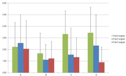
[image:6.595.70.283.297.425.2]The purpose of the experiments was to investigate whether humans can interpret haptic signals as denoting spatial directions. A first question was how 'natural' or intuitive the chosen target areas are. Fig. 6 and Fig. 7 show the average absolute original error scores and relative error scores for all participants across the three trials (0, 2 and 5).
[image:6.595.64.283.468.599.2]Figure 6, Average original error scores in absolute values, target A associates with L1, target B with R1, C with L2 and D with R2 (lines on top of the bars represent average plus standard deviations)
Figure 7, Average relative error scores in absolute values, target A associates with L1, target b with R1, C with L2 and D with R2 (lines on top of the bars represent average plus standard deviations).
Table II shows the standard deviation for each target area and Fig. 8 provides a spatial representation of the error intervals in the Pre-Test; the intervals are the average error plus and minus the standard deviation (covering 68% of error scores). The figure shows that even though there might be a considerable error, the participants' interpretation of target area C (far left) did not overlap with area A (near left), nor did area D (far right) overlap with area B (near right). It can be concluded that the chosen target areas were intuitively distinguishable across different individuals.
B. Associating vibration signals with spatial directions
The next point to investigate was whether subjects can associate the vibration signals on the forearm with spatial
directions; that is, the target areas A to D. None of the subjects made a real error: as the vibration motors were activated, beginning with trial 2 (and also latter on) subjects never pointed to a wrong target area.
TABLE II. STANDARD DEVIATION PER TARGET AREA PER TRIAL
Target area
Standard deviations and Average
SD trial 0
SD trial 2
SD trial 5
Avera-ge all trials
SD all trials
A 2.11 2.44 2.46 2.25 1.78
B 1.73 1.32 1.45 1.16 1.06
C 2.00 2.30 1.68 1.55 1.62
D 2.19 2.66 1.32 2.07 1.72
Figure 8 Spatial presentation of the target positions (green) and from trial 0, the average error scores (green in Fig.6) and in red the plus and minus standard deviation (column 1 in Table II) intervals.
C. Positions of arm versus body in egocentric space representation
We introduced a relative error score in addition to the original error score, presented in Fig. 7. Fig. 9 presents the average absolute original and relative scores for each testing trial. The relative errors are slightly smaller than the original errors: this seems to indicate that the egocentric spatial representation uses the hand position (not the body position) as the point of reference.
D. Left or right oriented
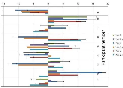
Another aspect we looked into is whether subjects were inclined to deviate to the left or to the right with respect to the position of body. Fig. 10 provides the summation of the error scores of each subject in each trial; negative error scores indicate an inclination to the left, positive error scores show a bias to the right. Some subjects showed a clear left hand side bias (subject 1) and some a right hand side bias (subjects 2 and 8); the other subjects did not evidence a particular bias.
[image:6.595.330.544.620.735.2]E. Effect of training with kinaesthetic cues
[image:7.595.53.295.244.417.2]Following reference [22] in trial 3 and 4 training with kinaesthetic cues was added. The average absolute original and relative error scores for all participants in trial 0, trial 2 and trial 5 are shown in Fig. 9. The average relative error scores are slightly smaller but both show the same slope of decrease. However, looking again at Fig. 10 no definitive conclusions can be drawn. The error scores of subjects 9 and 8 clearly decrease from trial0 to trial 5 (i.e. their performance improved) while the scores of subjects 7 and 5 remain approximately the same over the trials. However, the errors of subject 6 are increasing and swap from left to right.
Figure 10, Summation of error scores of each subject on each trial (lines on top of the bars represent average plus and minus standard deviations).
VI. CONCLUSION
This paper reported an experimental study on whether humans are able to associate haptic signals i.e. motor vibrations on the forearm, with spatial directions. It is known that pointing using a stick or handle leads to more accurate responses [21]. The pointing in the experiments should quite accurately represent a subject's intention and the Pre-Test shows that the four set target areas (A to D) are intuitively distinguishable. Also no major mistakes were recorded in reacting to the haptic signals. On average, accuracy in determining the four specified target areas improved over the sequence of trials. Introducing wooden blocks as training tools was useful, however the sequence of trial does not permit any conclusions as to whether the blocks were a better training tool than instructor's feedback would have been. The slightly smaller relative errors may indicate that the egocentric spatial representation uses the hand position (not the body position) as the point of reference.
Overall we conclude that the combination of a handle with vibration motor feedback has potential to contribute to wayfinding in poor audibility and visibility conditions.
REFERENCES
[1] J. Penders, L. Alboul, U. Witkowski, A. Naghsh, J. Saez-Pons, S. Herrechtsmeier, and M. El-Habbal, A robot swarm assisting a human
firefighter, Advanced Robotics, 25:93-117, 2011.
[2] Jacques Penders, Ayan Ghosh, Human Robot Interaction in the Absence of Visual and Aural Feedback: Exploring the Haptic Sense, Procedia Computer Science, Volume 71, 2015, Pages 185-195, ISSN 1877-0509,https://doi.org/10.1016/j.procs.2015.12.197.
[3] A. Ghosh, J. Penders, P. Jones and H.Reed. Experience of following a Robot using a Haptic Interface without Visual Feedback."IEEE Ro-Man 2014
[4] Haohao Yin, Weiwei Xia, Yueyue Zhang, Lianfeng Shen, "UWB-based indoor high precision localization system with robust unscented Kalman filter", Communication Systems (ICCS) 2016 IEEE International Conference on, pp. 1-6, 2016.
[5] Hull, J. M. (1990), Touching the Rock: An Experience of Blindness (London, SPCK).
[6] C. P. Gharpure, and V. A. Kulyukin, Robot-assisted shopping for the
blind: issues in spatial cognition and product selection, Intelligent
Service Robotics, 2008, Volume 1, Number 3, 237-251, DOI: 10.1007/s11370-008-0020-9.
[7] V. Kulyukin and A. Kutiyanawala, Accessible shopping systems for blind and visually impaired individuals: Design requirements and the state of the art, The Open Rehabilitation Journal, 2010.
[8] Fukasawa, AJ.; Magatani, K., A navigation system for the visually
impaired an intelligent white cane, Engineering in Medicine and
Biology Society (EMBC), 2012 Annual International Conference of the IEEE , vol., no., pp.4760,4763, Aug. 28 2012-Sept. 1 2012.
[9] Adame, M.R.; Jing Yu; Moller, K.; Seemann, E., A wearable navigation aid for blind people using a vibrotactile information transfer
system, Complex Medical Engineering (CME), 2013 ICME
International Conference on , vol., no., pp.13,18, 25-28 May 2013. [10] Bousbia-Salah, M.; Fezari, M., The Development of a pedestrian
navigation aid for the blind, GCC Conference (GCC), 2006 IEEE , vol.,
no., pp.1,5, 20-22 March 2006.
[11] Sadalla E. and D. R. Montello, Remembering changes in direction, Environment and Behaviour, vol 2 no 3, 1989.
[12] Klatzky, R.L (1998). Allocentric and egocentric spatial representations: Definitions, distinctions, and interconnections. In: Freksa, C., Habel, C., Wender, K.F. (eds.) Spatial Cognition 1998. LNCS (LNAI), vol. 1404, pp. 1–17. Springer, Heidelberg.
[13] Elyounnss M., Holloway A., Penders J., Alboul L. (2016) Development of an Intelligent Robotic Rein for Haptic Control and Interaction with Mobile Machines. In: Alboul L., Damian D., Aitken J. (eds) Towards Autonomous Robotic Systems. TAROS 2016. Lecture Notes in Computer Science, vol 9716. Springer, Cham
[14] GHOSH, Ayan, PENDERS, Jacques, JONES, Peter, REED, Heath and SORANZO, Alessandro (2014). Exploring haptic feedback for robot to human communication. In: SHARKEY, Paul, PARETO, Lena, BROEREN, Jurgen and RYDMARK, Martin, (eds.) The 10th International Conference on Disability, Virtual Reality and Associated Technologies, Proceedings. Reading, University of Reading, 309-312. [15] T. Meilinger, and G. Vosgerau, Putting egocentric and allocentric into
perspective, 7th international conference on Spatial cognition, 2010 [16] N. Burgess, Spatial memory: how egocentric and allocentric
combine.Trends in cognitive sciences,10(12), 551-557. 2006
[17] R. Frances Wang, Elizabeth S. Spelke, Updating egocentric
representations in human navigation Journal: Cognition , vol. 77, no. 3,
pp. 215-250, 2000
[18] M. Amorim, S. Glasauer, K. Corpinot, and A. Berthoz Updating an object's orientation and location during non-visual navigation:A comparision between two processing mode, Perception & Psychophysics 1997, 59 (3), 404-418
[19] A. Etienne, and K, Jeffery, Path Integration in Mammals, Hippocampus 14, pp180-192, 2004.
[20] G.A. Gescheider.Cutaneous sound localization. Journal of Experimental Psychology, 70(6), 617-625,1965
[21] L. Haber, R. N. Haber, S. Penningroth, H. Novak, & H. Radgowski,
Comparison of nine methods of indicating the direction to objects: Data
from blind adults. Perception, 22, 35-47, 1993
[22] D. Tan, J. Stefanucci, D, Proffitt, R. Pausch, Kinesthetic Cues Aid
Spatial Memory Proceeding CHI EA '02 CHI '02 Extended Abstracts on
Human Factors in Computing Systems Pages 806-807 Minneapolis, Minnesota, USA — April 20 - 25, 2002