Implementation Of Distributed Mosaic Formation And
Object Detection In Modular Robotic Systems.
AHMED, M Shuja, SAATCHI, Reza <http://orcid.org/0000-0002-2266-0187>
and CAPARRELLI, Fabio
Available from Sheffield Hallam University Research Archive (SHURA) at:
http://shura.shu.ac.uk/13708/
This document is the author deposited version. You are advised to consult the
publisher's version if you wish to cite from it.
Published version
AHMED, M Shuja, SAATCHI, Reza and CAPARRELLI, Fabio (2013). Implementation
Of Distributed Mosaic Formation And Object Detection In Modular Robotic Systems.
In: Proceedings of the 3rd International Conference on Pervasive Embedded
Computing and Communication Systems. Scitepress, 135-138.
Copyright and re-use policy
See
http://shura.shu.ac.uk/information.html
IMPLEMENTATION OF DISTRIBUTED MOSAIC FORMATION
AND OBJECT DETECTION IN MODULAR ROBOTIC SYSTEMS
M Shuja Ahmed, Reza Saatchi and Fabio Caparrelli
Materials and Engineering Research Institute, Sheffield Hallam University, Sheffield, United Kingdom m [email protected], [email protected], [email protected]
Keywords: Distributed vision processing, Modular robotics, Object detection, Image Mosaic
Abstract: In reconfigurable modular robotics, when robot modules joins to form a robotic organism, they create a tributed processing environment in a unified system. This research builds on the efficient use of these dis-tributed processing resources and presents the manner these resources can be utilised to implement disdis-tributed mosaic formation and object detection within the organism. The generation of mosaics provides surrounding awareness to the organism and helps it to localise itself with reference to the objects in the mosaics. Whereas, the detection of objects in the mosaic helps in identifying parts of the mosaic which needed processing.
1
INTRODUCTION
In reconfigurable modular robotics, the robot mod-ules physically join together to form different shapes of organisms which are inspired from the nature (e.g. snake, wheel shape and walking system) as described in (Yim et al., 2007)(Zhang et al., 2003)(Fukuda and Nakagawa, 1988). These systems are also described as “Networked Robotics” in (Kumar et al., 2006), be-cause the individual robot modules establish a munication network between each other. The com-munication network helps the robot modules to share their knowledge. In the recent research (Kernbach et al., 2009), a complicated modular robot is pre-sented in which robot modules share their energy, memory and computing resources in the organism. An example of energy sharing, in terms of physical pull, is described in (Tuci et al., 2006) where mul-tiple robot modules drag heavy objects. The shar-ing of the computshar-ing resources among robot mod-ules introduces the concept of distributed computing in robotics (Defago, 2001) (Brugali and Fayad, 2002). For distributing computing, the presence of a reliable communication medium is essential. The provision of physical communication medium in the organism facilitates the utilisation of distributed processing re-sources within it. In modular robotics, as the indi-vidual robot have limited memory and processing re-sources, so the use of vision sensors is usually avoided because of the computationally demanding nature of the vision algorithms. But in the robotic organism, as a reliable communication medium and rich
process-ing environment is generated, so this facilitates the distributed implementation of vision algorithms.
In this research a distributed modular robotic sys-tem is considered (Replicator, 2008)(Kernbach et al., 2008). Using the high speed communication and computational resources within the organism, the task of distributed vision processing is performed. A sce-nario is considered in which a multi-processor robot (simulating the organism) is used. The master module in the robot becomes responsible for the robot loco-motion and recognition of landmarks. Whereas, the two slave modules gather the surrounding informa-tion of the landmark by collectively generating the image mosaic, and then detecting the objects in the mosaic. The locations of these detected objects in the mosaic, with reference to the landmark, can be help-ful if later on, a robot has to reach a specific object. To achieve this, the robot can relates the object it ob-serves with the objects present in the mosaics. On finding a match, it obtain clues about which direction to proceed to find the object.
2
METHODOLOGY
used, as shown in Figure 1. For distributed process-ing, the entire vision processing task was divided into three sub-tasks, where each sub-task was assigned to an individual processing module as shown in Figure 1. The master module performs the robot locomotion and landmarks recognition. To recognise landmarks, the master module was provided with the SURF fea-tures of the landmarks. On recognising the land-mark, the master module rotated the robot, scanned the environment and passed the stream of images to slaves 1 and 2 robots. Slave 1 robot extract SURF features, computed homographies and passed homo-graphies information to slave 2 robot. Slave 2 re-ceived the stream of images from the master robot and the corresponding homographies from slave 1. Using the homographies, slave 2 robot stitched the images together to generate mosaic and finally detected the presence of the objects in the surrounding of the land-mark.
Figure 1: Allocation of tasks within the organism.
2.1
Homographies Computation
While rotating the robot, the master module streamed the QVGA (320x240 pixels) resolution images to slave 1 module. Originally, the master module grabbed VGA (640x480 pixels) resolution images, but to reduce the load on the communication medium and to reduce the SURF features extraction time on slave 1 module, the images were sent to slave 1 in QVGA format. After extracting the SURF features, slave 1 robot performed matching of features ex-tracted from two consecutive images. These matching features were processed with RANSAC “RANdom SAmple Consensus” algorithm to remove any outlier features. The final matching features were then used to extract homography between the two images. Slave 1 robot forwarded these homographies information to the slave 2 where it was used to generate the image mosaics.
2.2
Mosaic Formation
Slave 2 received VGA resolution images from mas-ter module and homographies from slave 1 to stitch the images together. To form a mosaic, slave 2 com-puted the product of all the received homographies in incremental fashion and at each step of the product, the corresponding image was also re-projected on the mosaic. An example image mosaic is shown in Fig-ure 2a. As it is difficult to process this image mo-saic with computationally expensive recognition ap-proach. So it was decided to identify the parts of im-age containing the objects and consider them for pro-cessing. This makes the approach suitable for imple-mentation on an embedded system. For objects de-tection, first of all the segmentation of the complete image was performed and the region resulting from the ground and the boundary wall was isolated. In this case, the ground region surface and the boundary wall appears to be the same so they will appear in the same segmented region as shown in Figure 2b. This image is further processed and the number of image pixels in each column of a mosaic, contributing to the object presence are determined and the generated profile is shown in Figure 2c. This profile is threshold and the columns where the profile exceeds the threshold, sig-nals the presence of an object. Finally in Figure 2d, the pixels contributing to the object are filled with the Blue colour.
[image:3.595.309.521.465.674.2]3
RESULTS
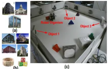
This section presents the experimental results. For experimentation, the multi-processor robot was pro-vided SURF features of the target landmarks, that is the building images shown in Figure 3a. The SURF features of the landmarks were kept in the memory of master module as it was required to detect and recog-nise these landmarks. Some other images of unknown objects, shown in Figure 3b, were also used around the landmarks. These unknown objects help in gener-ating common features between two consecutive im-ages, when the images are processed for producing mosaics. The arena used for experimentation is also shown in Figure 3c.
[image:4.595.314.515.210.345.2]Figure 3: (a)Landmarks.(b)Unknown objects.(c)Test arena.
Figure 4: Trajectory made by the robot organism.
During the experiment, the trajectory followed by the robot, when it searched for landmarks and gen-erated mosaics, is shown in the Red colour in Fig-ure 4. The starting and ending points of the trajectory are also indicated. The locations in the arena where mosaics were generated for landmarks 1, 2 and 3, are shown in Green, Yellow and Blue colour, respectively. The robotic organism first detected object 3 and gen-erated the mosaic for it. After detecting object 3, nine images were transferred by the master module to slave 1 and 2. The mosaic generated by slaves 1 and 2 for object 3, is shown in Figure 5a. The number of
pix-els profile, contributing to detect the presence of ob-ject in the mosaic, is shown in Figure 5b. This profile was obtained when the mosaic in Figure 5a was seg-mented and the ground region was removed from the segmented image, as discussed in the Methodology Section. Finally, after thresholding this pixels profile, the number of objects were detected in the mosaic. The detected objects are identified by the blue pixels and are shown in Figure 5c.
Figure 5: (a) Object 3 mosaic. (b) Pixels contributing to object existence. (c) Object detection in mosaic.
Similarly, the mosaics information generated for target landmarks 1 and 2 is shown in Figures 6a and 6c, respectively. All the objects in the mosaic view are properly detected and isolated from the ground surface as shown in Figures 6b and 6d.
Figure 6: (a) Object 1 mosaic. (b) Objects detected in mo-saic. (c) Object 2 momo-saic. (d) Objects detected in momo-saic.
[image:4.595.92.266.279.390.2] [image:4.595.80.281.431.559.2] [image:4.595.313.515.461.645.2](320x240 pixels) resolution was selected for solving the homographies between the images using slave 1. But for generating the mosaics, the VGA (640x480 pixels) resolution was used by slave 2. To make the homographies information applicable to the VGA res-olution, every element in the homography matrix was required to scale up by a factor of 2. This way, all the objects were presented with their detail information in the mosaics.
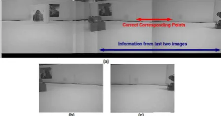
In experiments, it was noticed that, if not enough matching features are found between the consecutive images, then erroneous stitching of the images can occur. An example is shown in Figure 7a. In the beginning, the images were stitched properly. The problem occurred when the last two images shown in Figures 7b and 7c were stitched. The information contributed by these images is identified by the blue arrow. When these two images are compared with the mosaic, it can be noticed that they are stitched at wrong points. The two correct corresponding points where the image stitching should be performed, are identified with red arrow. Although there is sufficient overlap between these images, there are no objects in this overlapping region. This causes reduced match-ing features between these images and false homog-raphy was computed.
Figure 7: (a) Erroneous Stitching in Mosaic. (b) Second Last Image for Mosaic. (c) Last Image for Mosaic.
4
CONCLUSION
In this study, a distributed mosaic formation and ob-ject detection approach in a multi-processor robot was presented. The overall task was distributed among three processing modules. This distributed implemen-tation enables the master processing module to focus on the robot locomotion task as it can process the images at faster rate. At the same time, the master module utilises the processing resources of the slave robots to perform the computationally expensive task, that is mosaic generation and object detection. During
the experiments, it was observed that, if small number of objects are present on the location where a robot tries to generate mosaics, then erroneous stitching of the images is expected. The reason for this was the lack of common features between the two consecu-tive images. To overcome this problem, the use of a compass in the robot can also be made.
ACKNOWLEDGEMENTS
Funded by EU-FP7 research project REPLICATOR.
REFERENCES
Brugali, D. and Fayad, M. (2002). Distributed computing in robotics and automation. InTransactions on Robotics and Automation, Vol. 18, No.4, Pages: 409-420. Defago, X. (2001). Distributed computing on the move:
From mobile computing to cooperative robotics and nano robotics. InIn Proc. 1st ACM Intl Workshop on Principles of Mobile Computing, Pages 49-55. Fukuda, T. and Nakagawa, S. (1988). Dynamically
recon-figurable robotic system. In Proc. of Intl. Conf. On Robotics and Automation, Vol.3, Pages:1581-1586. Kernbach, S., Hamann, H., and Stradner, J. (2009). On
adaptive self-organization in artificial robot organ-isms. In The First International Conference on Adaptive and Self-adaptive Systems and Applications (ADAPTIVE), Pages: 33-43.
Kernbach, S., Szymanski, M., Schmickl, T., and Corradi, P. (2008). Symbiotic robot organisms: Reprlicator and symbrion projects. InPerMIS, Special Session on EU-projects, Pages: 62-69.
Kumar, V., Bekey, G., and Sanderson, A. (2006). Chap-ter 7 networked robots, assessment of inChap-ternational re-search and development in robotics, pages: 73-80. In http://www.wtec.org/robotics/. NASA.
Replicator (2008). Robotic evolutionary self-programming and self-assembling organisms. In 7th Framework Programme Project No FP7-ICT-2007.2.1. European Communities, URL: http://symbrion.org/.
Tuci, E., Gro, R., Trianni, V., Mondada, F., Bonani, M., and Dorigo, M. (2006). Cooperation through self-assembling in multi-robot systems. InACM Trans-actions on Autonomous and Adaptive Systems, Vol.1, No.2, Pages: 115-150.
Yim, M., Shen, W., Salemi, B., Rus, D., Moll, M., Lipson, H., Klavins, E., and Chirikjian, G. (2007). Modular self-reconfigurable robot system. InRobotics and Au-tomation Magazine, Vol.14, No.1, Pages:43-52. Zhang, Y., Yim, M., Eldershaw, C., Duff, D., and Roufas,
[image:5.595.73.299.405.523.2]