A Methodology for Provably Stable Behaviour-based Intelligent
Control
Christopher J. Harper, Alan F.T. Winfield
Intelligent Autonomous Systems Laboratory, University of the West of England, Bristol, UK {[email protected], [email protected]}
Abstract
This paper presents a design methodology for a class of behaviour-based control systems, arguing its potential for application to safety critical systems. We propose a formal basis for subsumption architec-ture design based on two extensions to Lyapunov stability theory, the Second Order Stability Theorems, and interpretations of system safety and liveness in Lyapunov stability terms. The subsumption of the new theorems by the classical stability theorems serves as a model of dynamical subsumption, forming the basis of the design methodology. Behaviour-based control also offers the potential for using simple computational mechanisms, which will simplify the safety assurance process.
Keywords:
Intelligent control; behaviour-based control; Subsumption Architecture; Lyapunov stability; safety critical systems.
1.
I
NTRODUCTIONIntelligent control techniques have not to date found widespread application in systems that demand high levels of dependability, such as safety critical systems. There are two reasons for this. Firstly, intel-ligent control systems, based upon recent techniques from artificial intelligence or mobile robotics are difficult to validate formally using conventional approaches to system analysis and test. Secondly, researchers in artificial intelligence are often content to demonstrate intelligent control in laboratory environments only; their interest is generally in pushing the boundaries of AI, rather than transferring techniques into mainstream engineering practice. In this paper we present an investigation into methods that will allow intelligent control systems to be used in the same manner as conventional control systems are used today.
1.1 Background
A system is safety critical if its failure or malfunction can cause damage, injury, or loss of life [18]. Typical examples include aircraft control systems, nuclear power station controls, or industrial process controls. Safety critical systems are required to undergo a safety certification process prior to their intro-duction into service. Within this process, the safety properties of the system are rigorously validated, to establish that it will be safe within a known range of environmental conditions. The process involves extensive systems analysis, design verification, and testing.
validation methods such as static analysis or testing [37]. Safety is generally demonstrated by various failure analyses (functional and non-functional) and then by more specialised testing processes such as environmental testing, reliability testing, and fault injection testing.
It is beyond the scope of this paper to investigate the definition of ‘intelligence’, but it is possible to provide some characterisation of “intelligent control”, and the general nature of systems of this category. One of the most succinct definitions proposed to date is due to Newell and Simon [27], who state that ‘general intelligent action’ as any behaviour occuring in a real situation that is appropriate to the ends of the system and adaptive to the demands of the environment, within some limits of speed and complexity.
This definition highlights several aspects of intelligent control:
(1) That intelligent control is defined not by the nature of the internal mechanisms of a system, but by the external interactions between that system and its environment.
(2) That intelligent systems adapt to their environment and not vice versa. Many conventional engi-neering systems are made reliable by designing their environments rather than the systems them-selves.
(3) That intelligent control systems can adapt to their environment and still be able to achieve their goals. It should not be assumed that environments are in any way benign, or that they should remain so.
Intelligent control techniques have hitherto been largely ignored, or even actively rejected as unsuit-able for safety critical systems in many industry sectors. Yet intelligent control systems offer the prom-ise of increased levels of autonomy, adaptability or resilience to unexpected input conditions; attributes that will be increasingly required of future complex systems. The aim of this research, therefore, is to consider how intelligent control techniques may be designed so as to be able to predict or prove their operational properties in advance of their use in service. A design methodology answering these ques-tions would form the basis for the use of intelligent control in safety critical applicaques-tions.
The research described in this paper continues a strong thread of work, in the IAS laboratory, in prov-ably stable intelligent control. The work of Jin developed stability proofs for a class of adaptive neural controller [19]. Randall extended this research to systems with closed kinematic chains [31]. In the present work we turn our attention to a class of intelligent controllers based upon the subsumption archi-tecture, also known as behaviour-based control, first proposed by Brooks [7] and revised by Connell [9]. Behaviour-based control has become the approach of choice in mobile robotics research, yet no methods exist for assuring the dependability of such systems. Indeed, in the preamble to the reprinted version of his original paper [8], Brooks states:
“To my mind, there has to date been no decent mathematical analysis of the ideas presented in this paper [...] That is not to say that there should not be or can not be such an analysis. But I think it will require some very deep insights and can not rely on surface level equation generation.” 1.2 Related Work
Current research into design methodologies for behaviour-based systems tends to fall into two general approaches, informal guidelines, and formal techniques based either on discrete logic techniques, or continuous dynamical systems techniques (hybrid control theory [32] is a mix of discrete and continu-ous techniques). Within the latter two approaches, research efforts can also be split into two sub-catego-ries, those which apply formal techniques to characterise what is essentially an ad-hoc system design, and those which attempt to develop a formal theory of behaviour-based systems and then apply that the-ory to real problems.
not go to the point of explicit proof of these specifications, and so we regard it as being an informal (albeit a well-structured) technique.
Other researchers have developed formal methodologies using discrete logic approaches. Many of these techniques have been based on the definition of a formal language, specifying the function and properties of systems as predicates acting on propositions of agent states and actions. The LIKA lan-guage of Lesperance and Levesque [21] is typical of this approach. Of particular interest is the work of Amir and Maynard-Reid [2], who develop a full theory of subsumption architecture in discrete logic, including a model of the principle of subsumption. This is believed to be the only effort other than the one described in this paper that attempts to construct a full theory for behaviour-based systems, rather than providing formal descriptions of an ad-hoc design pattern.
Propositional languages have been successful as a design technique for behaviour-based agents, but suffer from symbol-grounding issues [15] when they are implemented in physical hardware. This tends to result in additional complexity within such systems, where an additional layer converting symbols to physical actions, and sensory patterns to symbols, must be added in order to make hardware work as intended. Techniques based on dynamical systems theory have the advantage that their representations of autonomous control problems can be expressed directly in physical hardware, allowing their imple-mentation in simpler computational mechanisms are required for symbolic techniques. For example, Beer [5] makes use of simple dynamical neural networks to provide gait control of hexapod robots and, as will be discussed later, the techniques defined in this paper can be implemented using programmable array logic. One can exploit the reduced complexity of these schemes to gain advantages in other aspects of system design. In the methodology discussed in this paper, the advantage gained is an improvement in the effectiveness of failure analysis, a key analysis requirement for certification of safety critical sys-tems.
Much research has made use of dynamical systems techniques to define design methodologies for behaviour-based (neuro-)control technologies, often using formal techniques to prove the goal-achiev-ing properties of systems. Particular examples include the work of Steinhage, Bergener et al. [35][36], Sequeira and Robeiro [33], and Low et al. [22]. However, as mentioned before, these approaches tend to involve the formal systematization of a system architecture, for which no theoretical basis has been defined. The research in this paper is believed to be the only dynamical systems methodology, which attempts to develop a mathematical theory of an architecture in a fully deductive manner from the ground up, rather than assuming a technological solution first and then developing a formalisation for it. 1.3 The Research
This paper describes a rational methodology for the design of systems with “Colony-style” architec-ture. This is a variant of Subsumption Architecture, which itself is one of many styles of behaviour-based control. The methodology [16] is intended to provide a formal basis for their design, by deduction of the transfer functions from the general dynamical model of a system and a specification of its required goals, and by deduction of the architectural organisation of a system from general principles for the minimisation of mutual interference between behaviour modules within its subsumption architec-ture.
2.
S
UBSUMPTIONA
RCHITECTUREThe work presented in this paper is a design methodology for Colony-style Subsumption Architecture (CSA), a form of behaviour-based system architecture. This section presents the characteristic features of behaviour-based systems generally, of CSA in particular, and the reasons for adopting this specific architecture type as the preferred technology for the safety critical systems design methodology.
2.1 Behaviour-based Systems
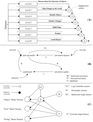
Behaviour-based systems first emerged in the mid-1980s, most notably from work by Brooks [7] but also from Arkin [3], Payton [28] and others. Many variations of behaviour-based system architecture have been developed over the intervening years and Figure 1 illustrates three different types, (A) Sub-sumption Architecture [9], (B) Action Selection Networks [24] and (C) Dynamical Neural Networks [6]. While these three architectures appear to be quite diverse, in general they share some characteristic prin-ciples and features.
(1) Typically, behaviour-based systems contain components that generate global system behaviour directly, rather than some specialised process that only partially contributes to the behaviour. In most behaviour-based systems, the architecture tends to be organised into concurrent arrays of behaviour-producing subsystems, referred to in Subsumption Architecture as ‘behaviour mod-ules’, a term which shall henceforth be used generically to apply to the functional components of any behaviour-based system.
(2) Behaviour-based systems exploit a simplifying principle, originally identified by Brooks [8], that cognition does not need an explicit process within an intelligent control system. Traditional AI theory was based on the idea that intelligent systems required specific processes that implemented cognitive reasoning. Brooks realised that for some types of behaviour (in particular those involv-ing sensorimotor coordination), a system that simply connected sensory perceptions directly to motor actions could still be seen as exhibiting cognition, if the pattern of actions was suitably arranged. This allows a fundamental simplification to be made in the internal design of behaviour modules over their earlier function-oriented counterparts in traditional AI systems. This simplifi-cation permits non-symbolic computational mechanisms to be used in the implementation of behaviour-based systems, which has major implications for their complexity, and hence their dependability assurance (as will be discussed later).
(3) The third feature they have in common is their use of behaviour arbitration. Since the behaviour modules of a system are all active concurrently, and each generates a distinct action command for the system, the specific action to be applied to the system must be selected out of the set of com-mands generated at any single moment. Many different schemes have been proposed, from fixed-priority arbitration (using suppression switches) in Subsumption Architecture to behaviour vector-summation [29] or excitatory/inhibitory signals [6][24].
Figure 1: Behaviour-based System Architectures.
Additionally, consider inductive inference techniques such as learning classifier systems or genetic algorithms. Inductive inference is not logically sound, and the safety properties of systems whose func-tional components have been developed by such techniques are difficult to argue. While techniques such as machine learning and evolutionary computing are important research topics in AI, they are not abso-lutely necessary to intelligent control, and the research presented in this paper has concentrated on developing a design methodology that is based on more conventional ‘manual’ design techniques based on deductive reasoning. This avoids the potential pitfalls of attempting to build a safety argument on inductive logic.
Of the architecture types considered, the most suitable candidate architecture is the Colony-style Sub-sumption Architecture. It employs all the essential functional elements and design principles of the behaviour-based systems concept, while being the technology with the highest degree of the causal properties required for effective safety analysis. Furthermore, while there have been experiments involv-ing the application of inductive learninvolv-ing techniques to the development of CSA systems [10], it is by no means absolutely necessary, as shown by Connell in his original development of the technology [9]. The design methodology presented in this paper has thus been applied preferentially to CSA.
Level 0
S
Avoid Objects Wander Build Maps Monitor Changes Identify Objects Plan Changes to the world Reason about the behaviour of objects
S
ensor
s
Level 1 Level 2 Level 3 Level 4 Level 5 Level 6
S
S
S
S
S
LC
P
B
F
“B”: Backward Angle Sensor
“F”: Forward Angle Sensor “Stance” Motor Neuron
“Foot” Motor Neuron
“Swing” Motor Neuron Excitatory
connection
Inhibitory connection
(A)
(B)
(C)
pick-up-sander
put-down-sander put-down-sprayer
sand-board STATE
GOALS
STATE B
B B
F
“B” : backward activation “F” : forward activation “I”: inhibition
Suppression switch
I
“LC”: Leg Controller neuron
2.2 Colony-style Subsumption Architecture
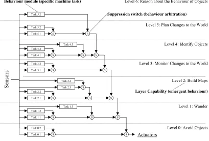
[image:6.595.98.507.213.490.2]Colony-style Subsumption Architecture (CSA) was developed originally by Connell [9], as an improved version of the original Subsumption Architecture of Brooks [7]. The basic functional compo-nent of Colony-style Subsumption Architecture is the behaviour module, which encapsulates all the con-trol activity required for the system to achieve a particular goal. The operational principle of the architecture is based on the notion that the transfer function of behaviour modules are partial functions, whose outputs are not defined for every possible input state. If modules do not generate output signals for all possible input states, their inactivity for some states allows other modules to control actuators if they occupy a lower-priority position within the system architecture. Figure 2, which has been adapted from Brooks’ original paper [7], illustrates the concept.
Figure 2: Colony-style Subsumption Architecture - a Class of Behaviour-based Control.
A complete system comprises many behaviour modules, each satisfying a separate goal, which com-pete with each other for control of the system actuators via an arbitration network. The theory presented in this paper considers only priority-based arbitration, in which modules illustrated as being higher in hierarchy diagrams such as Figure 2 override the signals generated by lower-level modules, hence tak-ing priority in their command of the machine/system. The principal type of arbitration mechanism employed in CSA (and the only one treated in this paper) is the Suppression Switch, for which the semantics are that the module providing the ‘vertical’ input overrides the module providing the ‘hori-zontal’ input, replacing the latter’s output signal with its own. If the higher-priority signal is inactive, then the lower-priority signal passes through to the switch output. Since the convention is that modules on a behaviour diagram such as Figure 2 are typically drawn such that those illustrated higher up in the diagram provide the ‘vertical’ input, then it follows from this convention that higher-level modules (and hence higher layers) take priority over lower level ones, and that the diagram therefore represents a hier-archy of behaviour modules. An arbitration network can therefore be built up, to integrate all the sys-tem’s behaviour modules together wherever they attempt to control the same system actuators. It may be the case, as shown in Connell’s original work on the MIT Herbert robot [9], that several arbitration net-works are needed, one for each actuator.
While suppression-type arbitration mechanisms are the only type considered here, the theory in this paper can readily be extended to the other types of priority-based mechanism, namely Inhibition
Se
nso
rs
Suppression switch (behaviour arbitration)
Behaviourmodule (specific machine task)
Actuators
Level 3: Monitor Changes to the World Level 4: Identify Objects
Level 0: Avoid Objects Level 1: Wander Level 5: Plan Changes to the World Level 6: Reason about the Behaviour of Objects
Level 2: Build Maps
Task 0.1 S
Task 1.3
S
Task 0.2 Task 1.1 S Task 1.2
Task 2.3
S Task 2.1 S
Task 2.2
Task 2.4 S Task 3.1 S
Task 3.2
Task 4.3
S Task 4.1 S
Task 4.2 Task 5.1 S Task 5.2 Task 5.2
Layer Capability (emergent behaviour)
S
S
S
S
S
Switches (where the higher priority input overrides the lower priority one without replacing it) and Release Switches (where the higher-priority input enables the lower-priority input to pass to the switch output).
Within the overall hierarchy of the system, sets of behaviour modules are composed to form layers. The concept of the layer is that it describes a new externally observable capability of the machine, which is achieved collectively by the set of modules it encapsulates. The intention behind identifying layers within a subsumption architecture is that they describe the emergent behaviour produced by a set of modules, when superimposed on the existing lower layers. The layer concept seeks to capture the notion that, by adding new individual behaviour modules that do highly specific tasks, the machine can achieve new behaviour that cannot be achieved by any single module on its own. A formal treatment of layers requires a formal theory of behavioural emergence in systems. A full theory of how layers can be identi-fied within a module hierarchy, or (more usefully) of how a layer description can be used to specify a set of behaviour modules (exploiting any emergence that may be achievable by such a decomposition), is the subject of ongoing research. However, the ideas presented in this paper that show how Lyapunov sta-bility theory (and the extensions developed here) describes the mechanisms of subsumption should form an underlying basis for this work.
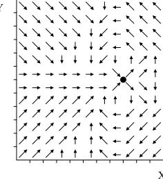
[image:7.595.239.357.383.512.2]Wherever possible, we propose to represent the transfer function of a behaviour module as a motor schema - a tabular representation of the velocity field in the state space that is required for a given behaviour pattern. An example for a ‘docking’ behaviour for a wheeled robot is illustrated in Figure 3. This is motion in which a robot approaches a goal position from one direction. It is intended to allow the robot to connect physically with some other object such as another robot or an electrical charging sta-tion, where an approach from a different direction would not allow such a connection to be made.
Figure 3: Example of a Motor Schema.
While recognising that the motor schema representation would not be applicable to all the behaviour modules in Figure 2, it is nevertheless our aim to represent as many of the layers as possible in this form, because the use of such a simple representation format allows the underlying computational hardware to be simplified, which brings benefits in terms of improved quality and reduced cost of safety assurance. These benefits are further elaborated in Section 8.
The methodology for designing individual behaviour modules is based on a new extension of Lyapunov stability theory, called the Second Order Lyapunov Stability Theorems. These theorems have two useful properties; they can prove the stability of the behaviour of a wider class of systems than is possible with the original Lyapunov Stability theorems (called the First Order Stability Theorems), and more importantly, stability can be achieved when only a partial control law function is defined for the system (if it satisfies the second order stability theorem). The first order stability theorems logically sub-sume the second order theorems whenever the system is behaving stably in the first order sense, and therefore it is not necessary for a function that is stable in the second order sense to be defined for such a condition. This logical subsumption property allows stable behaviour modules to be designed with par-tial functions, allowing them to be integrated into a subsumption architecture system.
3.
T
HES
ECONDO
RDERS
TABILITYT
HEOREMS3.1 The Mathematical Representation of Agent Behaviour
The central theme of our work is the development of a rigorous methodology for constructing CSA systems with provable safety and liveness properties. This requires a sound interpretation for the con-cept of intelligent behaviour, which allows a mathematical representation upon which rigorous methods of design and analysis can be based.
Behaviour-based AI draws extensively on ethology to provide the basic concepts of agent behaviour. Ethology generally proposes models of animal behaviour in terms of instinct patterns, such as Tinber-gen’s Innate Releasing Mechanisms model [38], an early attempt at a theory. Even though this model has subsequently been improved, most theories are still grounded in concepts such as instinct patterns, sen-sory stimuli, motor responses, inhibition, releasing, and so forth. Mathematical representations of these concepts are therefore necessary, and ethologists such as McFarland [26] have identified some key acteristics that permit mathematical or logical formalisation of descriptions of behaviour. Two key char-acteristics are that animal behaviour patterns are rational and purposeful. Animal behaviour is rational in that it is regular and consistent, and as such has one or more describing functions. It is purposeful in that behaviour patterns tend to be organised around goals, particular states or conditions that the animal tries to achieve, or perhaps avoid. This suggests that logically sound mathematical descriptions of behaviour are possible, if an appropriate notation can be found.
A third characteristic is that animal behaviour can be modelled using state spaces. Most ethologists tend to analyse behaviour by selecting some characteristic feature of an animal, or indicator of its condi-tion or that of its environment. Ethological studies often concentrate on measuring the change of these indicators over time, with the pattern of change indicating which mode of behaviour is being displayed. This leads to the idea that behaviour is the change in state of the relevant measures/indicators. For com-plex behaviours that are characterised by several parameters, the range of possible values that can char-acterise the behaviour form a state space. The state of the animal is then defined as a state vector, and the change of state (i.e. behaviour pattern) modelled as a state trajectory. Properties of behaviour patterns can therefore be defined as mathematical properties of state trajectories.
These characteristics, in addition to the general characteristics of intelligent control outlined in Section 1.1, permit behaviour patterns to be specified in terms of the respective goal conditions they must achieve and the nature of the environment in which the system is situated. This is captured in a dynami-cal model of the system to be controlled. A design process for a behaviour module would therefore need to construct a motor schema over a state space representing the behavioural problem to be solved, whose structure had mathematical properties that provided some guarantee that the goals would be achieved under the stated dynamical model. One mathematical property that stands out in its applicability to this type of problem (and is in popular use [14] [26] [36]) is Lyapunov stability.
3.2 Lyapunov Stability
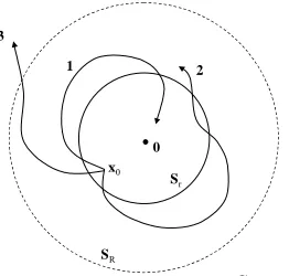
Figure 4: Types of Lyapunov Stability.
Lyapunov stability theory identifies three different categories of behaviour, based on the way in which state trajectories evolve over time. Curve 1 of Figure 4 illustrates Asymptotic Stability. If the state x0 of a system at time t0 (the initial moment of time being considered by the analysis) exists sufficiently close to some equilibrium condition (defined as x = 0), then the state trajectory will eventually converge on the equilibrium condition and remain there. This is formally defined by the following expression:
Asymptotic stability: (1)
The term represents Euclidean Distance, i.e. for an n-dimensional state vector. Equation (1) asserts that if the state vector at time t = 0 is within a ball of radius r around the equilibrium condition x = 0 (it is standard convention to place the equilibrium condition at the origin of the state space axes, thereby removing any constants from the distance terms), and the Euclidean dis-tance vanishes to zero (i.e. the state converges on the equilibrium condition) as time advances, then the system is asymptotically stable.
A second type of stability is Marginal Stability, as shown by Curve 2 in Figure 4. If the state x0 of a system at time t0 exists sufficiently close to the equilibrium condition, then it will always remain within some closed neighbourhood region (not necessarily the same one as the initial region) around the equi-librium condition. Marginal stability is formally defined by the following expression:
Marginal stability: (2)
This equation states that if the Euclidean distance at time t = 0 is within a ball of radius r around the equilibrium condition, then it will remain within a ball of radius R for all future time (where ).
A third type of behaviour is Instability, as represented by Curve 3 of Figure 4. Unstable trajectories are those that do not remain within any sphere around the equilibrium condition. Unstable trajectories do not require any characterising equation; any trajectory that is not asymptotically or marginally stable is unstable by definition.
Lyapunov’s theorems for the proof of marginal and asymptotic stability are based on the identification of scalar functions over a neighbourhood surrounding the equilibrium condition the state, called a Lyapunov function. If a Lyapunov function can be proven to exist for a system, then the system will have been proven to be marginally stable or asymptotically stable, depending on the properties of the Lyapunov function. For marginal or asymptotic stability, a candidate Lyapunov function V(x) must sat-isfy the following properties:
If, in a ball BR, there exists a scalar function V(x) with continuous first partial derivatives such that: (1) V(x) is positive definite (locally inBR)
(2) is negative semi-definite (locally inBR) Sr
SR
1 2
3
Curve 1: Asymptotically Stable
Curve 2: Marginally Stable
Curve 3: Unstable
x0
0
( )
( )
0, 0 , 0
r r t t
∃ > x < ⇒ → ∞ x →
x x =
(
x12+x22+ +K xn2)
( )
( )
0, 0, 0 0,
R r r t t R
∀ > ∃ > x < ⇒ ∀ ≥ x <
r
≤
R( )
then the equilibrium point is marginally stable.
(3) If, in addition, the derivative is locally negative definite in BR then the stability is asymp-totic.
It is assumed that the region of interest surrounds an equilibrium condition and that the origin point for the state variable axes is considered to be chosen so as to place the origin (x = 0) at the equilibrium con-dition. This is usually the case in most practical applications.
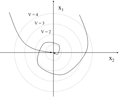
The original first-order Lyapunov stability theorems have been widely used within all branches of con-trol theory. However, there are constraints on what classes of trajectory can be proven stable with these basic theorems. The main issue is that the stability theorems are only sufficiency criteria, not necessity criteria. The theorems state that if a Lyapunov function exists for a system then it is stable. They do not say that a system is not stable if no suitable function can be found. The limitation of the Lyapunov stabil-ity theorems can be seen when one considers the trajectories of the systems whose stabilstabil-ity they can prove. The theorems can only prove that a system is stable if its trajectories always follow paths where the rate of change of the Lyapunov function along the trajectory is zero or negative (and only negative for asymptotic stability). Hence, only systems with trajectories like those shown for the two-dimensional state space in Figure 5 can be proven stable by the theorems.
[image:10.595.195.398.367.533.2]Many physical systems, and many control problems for those systems, cannot be modelled in such a way that the state trajectories are constantly convergent on an equilibrium condition. Inertia-dominated systems cannot be controlled so as to overcome their momentum instantaneously, and hence the direc-tion of their velocity cannot be governed directly.
Figure 5: Trajectories Displaying First Order Asymptotic Stability.
In particular, the behaviour patterns of many intelligent mobile agents are defined as position control problems, and since physical actuators control the forces applied to a system, it is only possible to gov-ern the acceleration (second derivative of position) directly. Hence, for Lyapunov stability techniques to be applied to such agents, we need an extension of the original theory (the Second Order Stability Theo-rems) in which the stability of a system’s position can be proven directly in terms of the forces (second derivative) applied to it.
3.3 Second Order Lyapunov Stability
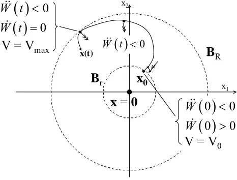
The new theorems are called Second-Order Stability Theorems because they introduce the second derivative of the Lyapunov function V(x), and allow the stability of a system to be proven within a wider set of constraints than is required for the First-Order Theorems. The concept underlying the theo-rems is the intuitive idea that, if V(x) is increasing along the system trajectories, then as long as it is ‘decelerating’ by more than a certain amount, its value will remain bounded, and this implies that the equilibrium condition x = 0 will be stable. This is represented graphically in Figure 6where the ‘decel-eration’ conditions, defining how a trajectory that is initially divergent from the equilibrium condition
( )
V& x
x1
x2
V = 4
V = 3
V = 2
can be made to become convergent again, are shown. Note: the function W(t) represents the change of value of V(x) along the system state trajectories as the system state evolves through time.
Second order stability can be said to be inspired by physical analogy, as was the first-order stability theory. The theory is analogous to the notion of a gravitational field of a point mass, where a particle will find its way towards the centre of such a field, and the trajectory of that particle will stabilise on that central point. However, if its initial velocity within the field of a Lyapunov function is too great (being analogous to the ‘escape velocity’ of a rocket, for example) then the state trajectory may exceed a given boundary neighbourhood of the centre and escape (instability). Figure 6 provides an illustration of this concept.
Theorem 1 - Second Order Marginal Stability:
Let x(t) define the time evolution of an autonomous system and let V(x) define a positive definite scalar function over a neighbourhood of x = 0. Let denote the value of V(x)along the system state trajectories. Hence and denote the rate of change and accelera-tion of the value of V(x) along the system's trajectories. The following theorem defines marginal stabil-ity in the second order:
[image:11.595.172.405.333.510.2](3) Stability is possible in the presence of positive initial conditions for , provided that they are bounded and that has a negative upper bound.
Figure 6: Graphical Representation of Second Order Stability.
The relationship between Vmax and V0 is defined by the equation:
(4)
Theorem 2 - Second Order Asymptotic Stability:
The following theorem defines asymptotic stability in the second order:
(5)
Note that, in this theorem, the first term is required to be negative definite, which is the criterion for asymptotic stability for the First-Order theorem.
Full proofs for these theorems are given in Appendix A and Appendix B respectively. x· = f x( )
W t( )≡V(x,t)
W·( )t ≡V·( , )xt W··( )t ≡V··( , )xt
W·( )t
≤
0∨
[
0<W·( )t <W·max∧
W··( )t <W··max<0]
→
[∀
R,∃
r>0, x( )0 <r→
x( )t <R] W·( )tW··( )t
x1 x2
x = 0 Br
BR
( )
0 0W&& <
x0
x(t)
V = Vmax
V = V0
( )
0W t&& <
( )
0W t&& <
( )
0W t& =
( )
0 0W& >
Vmax V0 W·max2 2 W··max
---+
=
W·( )t <0 [0≤W·( )t <W·max∧W··( )t <W··max<0]
R
∀ , ,∃r 0< <r R, x( )t <r→[ x( )t <R∧ x(t→∞) →0]
[ ]
⇒ ∨
3.4 Expressing Safety Properties Using Lyapunov Stability Theory
Given our aim, as stated in Section 1, to develop a methodology for behaviour-based systems for safety critical applications, it is necessary to define how safety and liveness properties can be specified in terms of Lyapunov stability concepts, so that we can translate a basic specification of a system’s mission, and a description of the hazards involved, into a specification of Lyapunov stability requirements that we can apply in the Direct Lyapunov Design process. We therefore require a model of how safety and liveness can be represented in these terms.
3.4.1 Liveness
Liveness is the easiest property to define in Lyapunov stability terms - it is directly equivalent to asymptotic stability. The definition of liveness given in Section 1 is that a system will achieve its func-tional purpose under all external conditions. Since the funcfunc-tional purpose of a behaviour module (and any instinctive behaviour pattern as defined in an ethological sense) is to achieve some goal condition that characterises the behaviour, the notion of liveness coincides with the notion of asymptotic stability if we define the goal condition to be achieved as the equilibrium condition of an asymptotically stable function, and the external conditions to be the initial conditions of the system and any disturbances imposed during its operation. Since all trajectories within a given region are proven to attain the equilib-rium condition, it follows that under the definition of equivalence proposed here, any asymptotically sta-ble function also possesses the property of liveness.
3.4.2 Safety
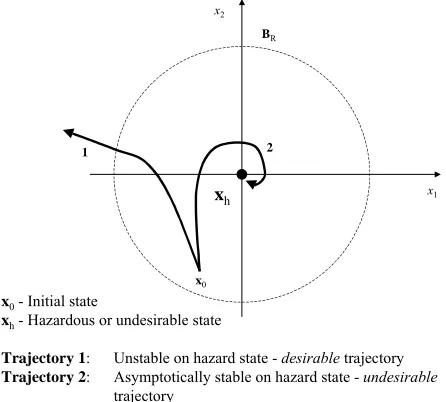
[image:12.595.182.405.441.642.2]The definition of safety as a property, given in Section 1, is that a system will avoid all conditions, which have been identified as hazardous, at all times over the course of its operation. This coincides with the concept of instability in the Lyapunov sense (see trajectory 3 of Figure 4), if we accept the def-inition that hazards can be defined as specific states (or regions of states), and that they are defined as conditions for functions, for which an instability proof exists, as illustrated in Figure 7.
Figure 7: The Expression of Safety Properties Using Lyapunov Stability Concepts.
The trajectories of a system proven to be unstable with respect to a particular condition will always leave a neighbourhood region of the condition for all future time, and hence it can be said that the sys-tem continuously avoids the given condition. Thus it follows that, under the equivalence definition pro-posed, any function that is unstable with respect to a given (hazard) condition (or set of conditions) also possesses the property of safety for that condition.
x0
BR
1 2
xh x1
x2
x0 - Initial state
xh - Hazardous or undesirable state
Trajectory 1: Unstable on hazard state - desirable trajectory Trajectory 2: Asymptotically stable on hazard state - undesirable
3.4.3 Dependability (Safety and Liveness Combined)
[image:13.595.201.407.135.300.2]For a system (or a behaviour module) to be truly dependable, it must possess both safety and liveness properties. Its state trajectories should therefore simultaneously converge on goals, while avoiding haz-ards, as illustrated in Figure 8.
Figure 8: Trajectories Combining Safety and Liveness.
3.4.4 Discussion.
While we have described in this section the criteria for safety properties, as a relevant part of this dis-cussion, a technique for proof-of-safety properties in motor schema will require a second order Lyapunov theorem for instability; this is work in progress. The experiment discussed in Section 7 con-sists only of a proof of the liveness properties of a system, not any safety properties.
The argument that Lyapunov stability properties can serve as expressions of safety and liveness prop-erties is contingent on our assertion of the equivalences between the parameters of safety, liveness, asymptotic stability and instability that we have proposed in this section. We believe that these defini-tions will prove to be useful, and will allow us to demonstrate that any CSA behaviour-based systems we develop will have the properties necessary to pass a safety certification exercise. The evidence for this will lie in experimental demonstrations, the first of which we present in Section 7.
4.
D
IRECTL
YAPUNOVD
ESIGNWe use the Second Order Lyapunov Stability Theorems as the basis for a design procedure for the motor schema of a behaviour module. Typically, the (first order) Lyapunov stability theorems tend to be applied by searching for a candidate Lyapunov function, which proves the stability of a control system transfer function that is already given. Since a motor schema is a piecewise function we adopt the inverse of this procedure, searching (piece by piece) for a motor schema, which ensures that the deriva-tives of a pre-defined positive-definite function are negative along the system state trajectories (thereby proving stability). Since we use the Lyapunov function directly as the basis for designing a motor schema, we have named the method Direct Lyapunov Design. The procedure is performed by the fol-lowing steps:
(1) Obtain a model of the open-loop dynamics of the system to be controlled. This can take the form of equations, explicitly defined maps, or some other model.
(2) Define the Goal State S required for the task, and the neighbourhood of S for which a task control-ler is required.
(3) Define a grid or mesh of points over the neighbourhood (each point is a state). x1
x2
HAZARD REGION
(4) For each point in the grid, select the control action that yields the most stabilising behaviour according to the second-order stability theorems, i.e. the action that yields the most negative value of . Make a record of and .
(5) Define a piecewise map function in which the grid points are the central states of each input-out-put pair, and their associated selected actions are the function outinput-out-puts.
(6) Define the V0 region by using Equation (4) and substituting the value of V(x) at the outer boundary of the neighbourhood for Vmax.
It should be noted that steps 3 and 4 constitute an inductive inference about the stability of a transfer function, because the stability of the function (a universally quantified statement) is inferred from a finite set of points (the mesh-grid of points) at which stability is calculated. Thus, stability is not strictly proven by this procedure. Therefore, as its stands, the procedure is not completely satisfactory for appli-cation to safety critical problems. However, for systems whose trajectories vary smoothly over the rele-vant neighbourhoods, the stability properties of the system should be preserved even where piecewise functions are defined with a finite set of input-output pairs, so for the purposes of our initial experi-ments, it was sufficient to develop some useful demonstrations (see Section 7).
It should be noted that this procedure is sufficient to design a motor schema that possesses liveness properties, but since there is no step for selecting control actions that are unstable with respect to any given condition labelled as hazardous, the procedure will not yield motor schema with provable safety properties.
5.
S
ECONDO
RDERS
TABILITYAS AM
ODELOFD
YNAMICALS
UBSUMPTIONWhile Second Order Stability was originally intended as a technique to assist the design of individual behaviour modules, one of the main breakthrough developments in our research has been the realisation that the theory also models many of the basic principles of Subsumption Architecture. In this section we explain how subsumption operates within subsumption architecture systems, and show how Second Order Stability theory can be used to model those operational principles.
5.1 Subsumption in Behaviour-based Systems
While the term ‘subsumption’ actually defines a specific logical property, it has also been used in a dif-ferent way to describe the operating principle of Subsumption Architecture systems. The term was first coined by Brooks [7] to describe the concurrent operation of layers within a system, and the incremental extension of a system, layer by layer, to achieve new capabilities. Each layer in a subsumption architec-ture (and even each module in CSA) operates entirely independently of any layer that may exist above it, As each new layer is added, it may draw upon behaviour already generated by lower layers if that behav-iour should be advantageous to the goals of the new layer, or it may override the lower layers by means of suppressing their outputs through the arbitration network. Behaviour modules in the new layer only add the minimum of extra behaviour patterns needed to get the new level of capability, and no more. In this way, higher layers are said to ‘subsume’ lower ones.
Since, in a priority-based arbitration network, the presence of any output signal from a behaviour mod-ule will override any other modmod-ule of lower priority, behaviour modmod-ules can only exploit the behaviour of lower-priority modules if they only generate output signals when it is necessary (for their purposes) to override the others. Hence, the transfer function of each behaviour module must be defined as a partial function which is not defined (and hence generates no signal) for the states in which the behaviour mod-ule can exploit the behaviour of the underlying system. If a behaviour modmod-ule had a fully defined func-tion, an output value would be generated for every possible input condifunc-tion, the behaviour module would be constantly active, and it would completely suppress every other module of a lower priority. This would prevent the goals of the lower-priority modules from ever being achieved, and thus the abil-ity of the system as a whole to achieve multiple goals would be destroyed.
For reasons that will be explained later, we refer to the principle of exploiting the behaviour of under-lying layers as “dynamical subsumption”, in order to emphasise the behavioural aspect of the principle and to distinguish between this concept and the notion of subsumption in formal logic.
5.2 Modelling Dynamical Subsumption in CSA Systems using Second Order Stability
The development of the Second Order Stability theorems has offered a formal basis for the description of behaviour modules in Subsumption Architecture (or indeed in any priority-based arbitration scheme), and even offers a formal model of the principle of dynamical subsumption discussed in Section 5.1. We explain the argument in the following sections 5.2.1 to 5.2.3.
5.2.1 Logical Subsumption between the First and Second Order Lyapunov Stability Theorems
A partial logical subsumption relationship exists between the first order and second order Lyapunov stability theorems. The relationship becomes evident when the two asymptotic stability theorems are presented together:
First-order Asymptotic Stability: (6)
Second-order Asymptotic Stability: (7)
Equations (6)and (7)actually express the first order and second order stability parts of Equation (5) respectively. The full theorem as written in Equation (5) hides the subsumption relationship by merging the first and second order parts into one composite formula.
By comparing the first and second order theorems in this way, it can be seen that the first-order theo-rem subsumes the second-order theotheo-rem whenever is negative. The two theorems have the same conclusions. But the antecedent of the first-order theorem is expressed only in terms of while the second order theorem requires an additional term. Therefore, the first order theorem subsumes the second order one. However, the subsumption is not valid over every value of , only where it is neg-ative. Hence, the subsumption relationship is only a partial one, but it is this partial logical subsumption relationship that allows us to develop a formal model of subsumption in a Subsumption Architecture. 5.2.2 How Partial Functions Can Be Defined Using the Second Order Stability Theorem.
As we already mentioned in Section 3.3, the original reason for developing the Second Order Lyapunov Stability theorems was to provide a theory that could enable the proof of stability of behav-iour module whose transfer functions generated actuator commands directly as a function of position states. Since physical actuators generate forces, which govern the second derivative of a system’s posi-tion, the effect of actuators can only govern second derivatives in the Lyapunov functions we use to con-struct motor schema. Therefore, the transfer function of a behaviour module need only be defined for those states where the value of must be constrained in order to guarantee stability in the system state trajectory. For those states where the stability requires only a condition on the first derivative there is no second order term to determine, and hence no actuator command need be defined. Hence, only a partial function satisfying (7) is required, and a behaviour module designed using the Second Order Stability theorems can still guarantee the stability of a system even if there is no output defined where the state trajectory satisfies (6). Since we have established previously that priority-based arbitra-tion requires the use of partial funcarbitra-tions, it becomes clear that if a motor schema is designed using the second order stability theorems in the manner described, it can serve as a behaviour module in a sub-sumption architecture. The Direct Lyapunov Design procedure described in Section 4 achieves this objective.
5.2.3 How Logical Subsumption between the Stability Theorems Corresponds to Dynamical Subsumption between Subsumption Architecture Layers and Modules
W·( )t <0 →[∀R, ,∃r 0< <r R, x( )0 <r→[ x( )t <R∧[ x(t→∞) →0]]]
W·( )t <W·max∧W·max≥0∧W··( )t <W··max<0 →[∀R, ,∃r 0< <r R, x( )0 <r→[ x( )t <R∧[ x(t→∞) →0]]]
W·( )t
W·( )t W··( )t
W·( )t
W··( )t
In addition to enabling the construction of partial functions for behaviour modules, the Second Order Stability theorems also describe the principle of dynamical subsumption itself, the way in which higher priority modules exploit the activity of lower priority ones.
The key to this idea lies in the interpretation of the first-order stability terms, and what they represent about the behaviour of underlying layers relative to a given module. As we discussed in Section 5.2.3, a behaviour module transfer function need only be defined where the second derivative of the Lyapunov function requires constraint, as defined by (7). However, where the state trajectory satisfies (6), then no actuator function is necessary, and the transfer function need not be defined (and indeed, it should not, if the module is to be usable in a priority-based arbitration scheme).
Formula (6) identifies those conditions where the behaviour of a system satisfies the first order stabil-ity theorem for the goals of a behaviour module. For most practical control problems this describes the velocity motion of a system. The behaviour described by (6) specifies the ungoverned stable behaviour of the system, i.e. where the natural motion of the system is already convergent on the goals of a behav-iour module, and hence requires no overriding correction. Since the action of behavbehav-iour modules is to override any lower priority layer or module, the ungoverned behaviour described by (6) must represent the behaviour produced by lower layers that nonetheless satisfies the goals of the higher priority module, which the higher priority module exploits in order to achieve its goals. This is exactly the principle of subsumption set out by Brooks in his initial proposal of subsumption architecture [7], and reviewed in Section 5.1.
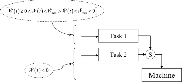
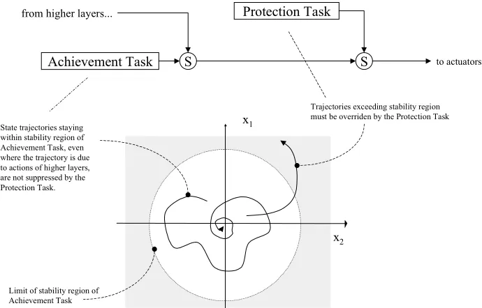
[image:16.595.143.450.362.502.2]This subsumption relationship relates to the elements of a Subsumption Architecture as illustrated by Figure 9.
Figure 9: Correspondence between the logical subsumption in the Second Order Stability Theorems and dynamical subsumption in a Subsumption Architecture.
At any given layer in the architecture, the behaviour modules of that layer need not take action if the behaviour generated by the underlying layers is naturally convergent on their goals (i.e. where formula (6)is satisfied). The underlying layers may include behaviour modules performing other tasks, or may just be the machine under control. Only when the state trajectories of the underlying system stop con-verging on the goal state(s) of the top level, i.e. where (6) ceases to be valid and actions that ensure the validity of (7) must be defined, is there a need for the behaviour module to select a control action with which to drive the system. This is done by means of the suppression switch, as shown in Figure 9, and the action taken by the top layer must satisfy the second-order stability theorems if the stability of its goal(s) is to be maintained.
As we discussed earlier, it is standard practice in behaviour-based control to state that higher-level behaviour modules subsume the activity of lower-level ones. However, from the argument presented in this section it can be seen that, in the logical sense at least, it is the lower levels of a system that partially subsume the upper levels, in that they may partially achieve the goals of the higher levels without requir-ing any explicit control module to do so. So, from a logical perspective, lower levels partially subsume higher ones. This reversal of precedence in the concepts of logical and dynamical subsumption is the reason why the term dynamical subsumption was introduced in Section 5.1, in order to avoid confusion
( ) 0 ( ) max ( ) max 0
W t W t W W t W
⎡ ≥ ∧ < ∧ < < ⎤
⎣& & & && && ⎦
S Task 2
Task 1
Machine ( ) 0
between the two. It is important to note that the great majority of papers and references on the subject (as typified by [7],[9],[25]and [28]) refer to dynamical subsumption, not logical subsumption.
6.
T
HED
ESIGNM
ETHODOLOGYThe methodology for integrating behaviour modules into a wider subsumption architecture is based on the concept of managing the interference between modules. When a higher-priority module suppresses or inhibits the output of a lower-priority module it isolates the lower-priority module from the actuators of the system. Therefore, the lower module cannot take any action to control the system, and the state of the system departs from the trajectory that was being generated by the lower-priority module. When the higher-priority module ceases activity, the lower-priority module can control the system once again, but it must do so from an initial state condition that could be a large distance from the goal state it must achieve. Hence, higher-priority modules impose disturbances upon the behaviour of lower-priority ones. The possibility exists that the higher-priority module could drive the system to such a departure from the goals of the lower-priority module that those goals are destabilised, and its activity will fail. There-fore, behaviour modules must be organised within a subsumption architecture to ensure that this does not happen.
The design methodology does this by two distinct measures.
(1) First, behaviour modules are organised in such a way as to minimise the mutual interference that higher-priority modules might impose on lower-priority ones. If a behaviour module is uniformly asymptotically stable, then it is totally stable, i.e. it remains at least marginally stable in the pres-ence of bounded disturbances. Therefore, as long as the relative interferpres-ence of one module upon another is minimised, then the modules can be arranged within a subsumption architecture without any further modification. The interference is minimised if the architecture obeys a constraint we have named the Diminishing Activity Principle:
The higher the priority of a module within an architecture, the lower the average mark-space ratio of its output activity should be.
A theorem is proposed, and proved, in Appendix C stating that the Diminishing Activity Principle yields the architecture with the minimum relative interference between the behaviour modules of a system.
sys-tem state remains within limits that ensure the function of its associated achievement module is valid.
Figure 10: Protection Modules.
The incorporation of these two measures into the structure of a subsumption architecture produces a standard model whose form and activity properties are illustrated in Figure 11:
Figure 11: Standard Model for Behaviour Module Activity and Organisation within a Subsumption Architecture.
In keeping with existing Subsumption Architecture concepts [7][9] the model is layered, each layer forming a new global capability of the machine being controlled. Each layer consists of achievement modules that perform the tasks required for the new global capability, and protection modules, which ensure that the operating limits required for stable operation of the achievement modules are maintained.
S Achievement Task
from higher layers...
to actuators
S Protection Task
x1
x2
Limit of stability region of Achievement Task
Trajectories exceeding stability region must be overriden by the Protection Task State trajectories staying
within stability region of Achievement Task, even where the trajectory is due to actions of higher layers, are not suppressed by the Protection Task.
A1 A2 A3
S
S
P2
P1
S S
Layer 1 Layer 2 Layer 4
An denotes an Achievement Module Pn denotes a Protection Module
S
A4
P3
S
Layer 3
Task 1 Activity
t Mark-space Ratio = 75%
Achievement Module Activity t
t Task 2 Activity
Mark-space Ratio = 50% Task 4 Activity
Mark-space Ratio = 12.5% t
Task 3 Activity
Mark-space Ratio = 25% t
[image:18.595.125.477.419.665.2]By following the arbitration rules established in the earlier discussion on design methodology the architecture model forms two internal hierarchies, an Achievement Hierarchy and a Protection Hierar-chy. The Achievement Hierarchy consists of all the behaviour modules (called achievement modules) that perform the required tasks of the system, and are organised with higher layers suppressing lower layers, according to the Diminishing Activity Principle (indicated by the activity profile graphs). The Protection Hierarchy consists of all the protection modules for the achievement modules in the other hierarchy. However, in accordance with the definition of protection modules, the arbitration network for the protection hierarchy is organised in the reverse sense to the achievement hierarchy, with lower-layer protection modules suppressing higher-layer ones. In this way, global capabilities can be added to a sys-tem without compromising the operation of lower layers through inter-module interaction.
7.
E
XPERIMENTS ANDD
EMONSTRATIONSAs a demonstration of the design methodology, we present a simulation of an aircraft flight control system that performs a simple ‘cruise control’ function. The purpose of the system is to control a simu-lated aircraft so as to achieve a steady ‘straight and level’ condition at a constant airspeed. In this exper-iment, we attempt only to establish liveness properties for the system, leaving the full demonstration of techniques for safety properties for future work.
7.1 Simulation Model
[image:19.595.132.472.404.643.2]The dynamical model of the aircraft is derived from the Body-Axes Model described by Etkin [13], making the ‘flat Earth’ assumption. Appendix D lists the equations of motion and the aerodynamic parameters used in the simulation.
Figure 12: Experimental Subsumption Architecture for a Flight Control System Simulation.
Figure 12 contains a schematic of the actual Subsumption Architecture that was developed. It shows how the experimental architecture follows the standard model of achievement and protection hierarchies as illustrated in Figure 11.
The architecture has two layers, the bottom layer performing velocity control behaviours and the top layer performing attitude control behaviour. The reason for this is that the dynamics governing aircraft velocities (see the Force Equations in the Body Axes in Appendix D) can be stabilised in the first order, using the classical Lyapunov stability theorems. Since functions that are stable in the first order are not partial functions, their activity ratio is 100% by definition. Therefore, they are required to occupy the
S
Velocity Control Layer Attitude Control Layer
Aileron demand δa
Elevator demand δe
Rudder demand δr S Level Out ψ θ φ p q r
Throttle demand δp
u v w Cruising Airspeed Cancel Sideslip θ φ p r u v w S S u v w Minimum Airspeed Velocity-based Rotation Control p r u v w Attitude-based Rotation Control ψ θ φ p q r S Velocity-based Bank Control φ u v w
lowest layer. The dynamics of the aircraft’s attitude (see the aircraft attitude kinematics equations in Appendix D) can only be stabilised in the second order, and hence the behaviour module is a partial function whose activity ratio is by definition less than 100%. Therefore, the attitude control layer must take the higher priority.
The structure of the architecture in Figure 12 follows the general pattern defined in Figure 11. The architecture contains an Achievement Hierarchy and a Protection Hierarchy, and the order of priority in the protection hierarchy is the reverse of that in the achievement hierarchy. The protection modules are designed to prevent the state of the system exceeding limits that prevent their respective achievement modules from achieving their stated goals. These limits are derived from the flight dynamics equations of the aircraft, as presented in Appendix D.
7.2 Results
[image:20.595.156.459.373.607.2]The aircraft simulation was run for a variety of different initial conditions. The goal condition of straight and level flight is defined as zero deflection in any attitude, zero velocity in the downwards and sideslip direction, and a steady forward velocity of 67 ms-1. The state trajectories of the system were plotted in two state trajectory portraits, for attitude and velocity. These portraits are shown in Figure 13 and Figure 14. The first diagram is a portrait of the three attitude variables (azimuth, elevation, and bank). The second diagram is a portrait of the velocities in the three axes of symmetry of the aircraft (forwards, downwards, and sideslip velocities).
Figure 13: Airframe Attitude Trajectories.
shown in the foreground in the lower half of Figure 13. The motion of this trajectoryinitially diverges from the goal state before ‘turning a corner’ and becoming convergent, similar in structure to the trajec-tory illustrated in Figure 6.
From the nature of the state trajectories on display in Figure 13, we draw the following conclusions: (1) One can readily apply the second order stability theorems to obtain a proof of Lyapunov stability
for systems. Furthermore, the second order theorems can be used to prove the stability of systems with trajectories that are initially divergent, a result that cannot be achieved using the first order theorems.
[image:21.595.123.462.252.452.2](2) The fact that the trajectories cover an extended region surrounding the specified ‘straight and level’ goal condition and that they all converge on a much smaller region, demonstrates the live-ness of the “Level Out” module, which is the achievement module in the attitude control layer.
Figure 14: Airframe Velocity Trajectories.
The velocity variables whose trajectories are illustrated in Figure 14 are characterised by two features, an initial relatively smooth part, followed by the onset of a highly noisy part, with many high-frequency disturbances as the trajectory closes in on the goal condition. This is in contrast to the attitude trajecto-ries in Figure 13, which remain relatively smooth until they reach their region of marginal stability around the equilibrium condition.
It should be noted that all the behaviour modules governing aircraft velocity in the three axes are defined by complete functions, which were actually designed by the application of first order stability theorems. It may be that this makes their operation much more sensitive to disturbances, because they are defined for every possible condition of their respective state spaces. Any disturbance at all will be met with a corresponding control action, yielding a trajectory that picks up all the interference between modules. In contrast, the attitude control modules, which were designed using the second order stability theorems, are partial functions which do not always generate control actions. Only where a disturbance produces a motion that requires action to restore the conditions of the second order theorem, as per Equation (5), will such a module generate an action. This has the effect of reducing the amount of activ-ity generated in response to inter-module interference. In the velocactiv-ity control modules, this phenomenon does not arise, and the trajectories are consequently more noisy.
7.3 Conclusions of the Experiment
We consider these results to demonstrate that the methodology described in this paper can produce via-ble behaviour-based systems with Colony-style Subsumption Architecture, in which the behaviour
ules have been proven to be stable, which implies that liveness has been established. The results presented in Figure 13 and Figure 14 present an initial confirmation of the methodology and its underly-ing theories.
However, there are some limitations to what has been demonstrated. One significant limitation was the lack of smoothness in the state trajectories, which is brought about by conflicting interactions between behaviour modules, especially when the state trajectories are close to the goal conditions of the behav-iour modules. Future work is aimed at improving the smoothness of behavbehav-iour generated by this type of subsumption architecture, by use of stability theorems of a higher order than the second. We are confi-dent that the proofs for the second order theorems can be extended to the third order or higher.
Another set of limitations were the ideal assumptions made about the performance capabilities of sys-tem components. For example, it was assumed that actuators can change state instantaneously, which is not possible in real physical mechanisms. Therefore, the motor schema produced for the simulation may not have the same liveness properties if they were applied directly to a real aircraft. We believe, how-ever, that the use of higher order stability theorems (possibly a third order stability theorem) will over-come this limitation. We aim to develop and apply this idea in future experiments (see Section 8).
Nonetheless, in spite of the limitations discussed above, we believe that the results of the experiment do validate the argument that safety and liveness properties can be specified in terms of Lyapunov stabil-ity and that these properties can be established formally within the motor schema of a CSA system.
8.
C
ONCLUSIONSANDF
UTUREW
ORKThere are a number of conclusions to be drawn from the work presented in this paper, which have implications for future studies in this direction. Section 8.1 reviews the main conclusions to date, and sections 8.2 and 8.3 discuss some of the major directions in which we intend to pursue this research. 8.1 Conclusions of the Work to Date
The body of work presented in this paper forms the core of a design methodology aimed at the devel-opment of intelligent systems for safety critical application. The methodology includes a procedure for designing a behaviour-based system with a Colony-style Subsumption Architecture and proving the sta-bility of the resulting design.
Since it is our intention that the methodology be suitable for developing behaviour-based systems for safety critical applications, we have developed a formal mathematical basis for their design, to provide the same level of rigour to the methodology that is achieved with conventional systems engineering technologies. We have developed a methodology from first principles, so that every concept in use had a mathematical representation derived from the basic concepts of behaviour. Some definitions, for exam-ple the definitions of how safety and liveness can be expressed in Lyapunov stability terms, have been asserted as a priori arguments. However, we believe that the experimental work done so far validates the approach.
While the methodology is primarily intended for application to systems [9], the basic theorems of sta-bility, and their association to safety properties, makes no specific assumption at that level about the type of technology to be used. Therefore, this methodology may be adaptable to architecture types other than CSA. In particular, if the proposed models of different arbitration schemes (in Section 8.2) are success-fully added, then we believe there to be significant scope for widening the applicability of the methodol-ogy.
8.2 Further Developments to the Design Methodology
While this work provides the core of a methodology, it is not complete. Further work will include: (1) A Second Order Stability theorem for instability, which is the necessary basis for defining safety
implies that the state of a system would never come closer (in Euclidean distance terms) than some determinable value. We believe such a theorem should be derivable in a similar manner to the proofs given in Appendix A and Appendix B, but applied in the inverse sense. We aim to develop this theorem and apply it in new experiments to demonstrate the achievement of safety properties as well as liveness.
(2) A Layer Theory for CSA to account for how the behaviour of modules can combine to form an emergent capability that is referred to as the Layer in subsumption architecture terms. We believe this will require elements of environmental analysis, where we derive the specification of individ-ual behaviour modules by studying the features of the environment in which the system is intended to be situated.
(3) An extension to the modelling of subsumption principles into non-priority based arbitration schemes. One possible mathematical basis for doing so might be based on the Passivity Theorems of Lyapunov stability theory [34]. These theorems prove that the outputs of certain classes of con-troller, independently proven to be stable, can be summed together and the composite system will still remain stable. We consider this to be a possible basis for proving the stability of ‘command-fusion’ styles of behaviour arbitration. If this development can be achieved, then we may be able to apply our methodology to many types of system architecture other than CSA.
8.3 Further Developments - Computational Hardware
A significant area for further exploration is how to exploit the potential benefits of the simplifying principle of behaviour-based systems (discussed in Section 2.1) for reducing the complexity of the hard-ware required to support such a system (compared to conventional microprocessor hardhard-ware). Since the experiment presented in Section 7 was a simulation, we have not yet investigated this potential.
The use of motor schema as the basis for implementing behaviour modules in CSA systems, as described in Section 2.2 has, we believe, an inherent advantage over conventional (symbolic) computers for the development and certification of safety critical systems. It may be possible to implement these systems using simpler computational mechanisms than microprocessors, with the potential for improved fault detection and tolerance over conventional microprocessors.
Motor schema are memory-less functions, and without the need for local internal memory behaviour modules can be constructed from pure combinational logic rather than synchronous circuitry. It is possi-ble to implement these behaviour modules using Programmapossi-ble Array Logic (PAL/PLA) devices, as shown in Figure 15.
Figure 15: Implementation of Motor Schema in Programmable Array Logic.
The ability to use simpler implementations of functions leads to direct benefits in terms of the achiev-able diagnostic coverage and the improved possibilities for fault tolerant systems. The advantage of using relatively simple circuitry, such as programmable array logic, to implement motor schema means that the number of possible failure modes affecting the elements of the function are greatly reduced.
Further work will investigate this potential. We aim to move from simulation problems to physical machines (robots), with the subsumption architecture implemented using logic array devices, such as CPLD’s or FPGA’s. This will allow us to determine whether the arguments advanced in this paper can be exploite