doi:10.4236/eng.2010.27069 Published Online July 2010 (http://www.SciRP.org/journal/eng)
Dissimilar Welding of Superduplex Stainless Steel/HSLA
Steel for Offshore Applications Joined by GTAW
Bravo Ivan Mendoza1, Zepeda Cuauhtemoc Maldonado1, Hernandez Apolinar Albiter2, Piedras Eduardo Robles3
1
Instituto de Investigaciones Metalúrgicas-UMSNH, Morelia Michoacán, México 2
Instituto Mexicano del Petróleo, México, D. F., México 3
Instituto Nacional de Investigaciones Nucleares, La Marquesa, Ocoyoacac, México E-mail: ivanmendozabravo@gmail.com
Received January 15,2010; revised March 2, 2010; accepted March 13, 2010
Abstract
The dissimilar metal weld is demanding as well as the similar weld, however, dissimilar weld is more com-plex than similar weld due to the necessity of being applied in zones where a requirement is to improve some properties. In this work the main purpose is to know the mechanical behavior of a dissimilar weld between HSLA Steel and Superduplex Stainless Steel (SDSS) to establish if the joint is feasible or not. The alloys were welded with GTAW process using a 60-deg and 90-deg single-V groove test specimens in order to ob-serve the effect of the weld pass. The filler metal was chosen with the aid of Schaeffler diagram. It was found that the ER 25.10.4L filler metal provided the best equilibrium between ferrite and austenite phase in the Superduplex Stainless Steel final microstructure and a band of martensite in the HSLA steel final micro-structure. The dissimilar joint presented acceptable mechanical properties which are superior to the HSLA in the as-received condition, but lower than the SDSS in the as-received condition, proving that the filler metal was the adequate.
Keywords: Superduplex Stainless Steel, API X-52, GTAW, Dissimilar Welding, Pipeline
1. Introduction
The oil, gas and petrochemical industries have been us-ing API X52 pipes and other similar materials for off-shore and onoff-shore applications [1,2]. An important ap-plication of the API X-52 pipe is the exploitation and transportation of the hydrocarbons by Risers. However, the Riser has shown corrosion problems in the splash zone, especially three meters above and three meters below of the sea level. Sea water and tides cause cycles of wetting and drying on the Riser, promoting corrosion and therefore the failure of the pipeline. Currently, the Mexican Petroleum Industry has been using two solu-tions for this problem: 1) cathodic protection and 2) a carbon steel sleeve; however, both of them need perma-nent inspection and maintenance [3]. SDSS has an ex-cellent combination of mechanical properties and corro-sion resistance [4,5], making it suitable for applications with possibility of corrosion promoted by sea water [6-8], thus, other possible solution for this problem could be substituting the API X-52 pipe of the splash zone with
this superduplex stainless steels (SDSS).
Conventional arc welding process can be used to weld SDSS very easily when the parameters are the adequate to maintain the austenite/ferrite balance in the welding metal. However, the most important weldability prob-lems of SDSS are the changes in the austenite/ferrite balance that can affect the ductility if the ferrite percent-age is bigger than austenite, and promote the precipita-tion of intermetallic phases such as sigma phase which affect the corrosion resistance and toughness in the du-plex stainless steels [9,10]. On the other hand the API X-52 is also affected by the welding process but less than SDSS. To minimize these effects, is important to make a careful selection of welding materials and welding vari-ables [9,11,12]. Barnhouse et al., studied dissimilar
Keeping in mind those results, the purpose of this inves-tigation was established, therefore the first goal was to select the filler metal to maintain the microstructure bal-ance in SDSS and second, to study the effects of the welding designs and the filler metal to determine the mechanical properties and microstructural changes of dissimilar SDSS 2507/API X52 weld joints.
2. Experimental Procedure
To select the filler metal to employ in the dissimilar met-al welding (DMW), two filler metmet-als were considered ER 25.10.4L and ER 2209, with the aim of analyzing their effects on the microstructure using the WRC-1998 dia-gram developed by Kotecki which considers the marten-site boundary in the dissimilar metal joining and pro-vides more accurate information [14]. The application of this analysis was done considering the dilution at 50% on both filler metals. The chemical compositions of the al-loys are shown in Table 1 and were determined by opti-cal emission spectrometry (OES) and the nitrogen con-tent was determined by gas analysis.
The base materials employed API X-52 steel and SAF 2507 SDSS were supplied in pipe shape seamless with internal diameter of 101.6 mm (4 in) and nominal thick-ness of 6.35 mm (0.25 in). The pipes were cut into pieces of 100 mm-length and each section was machined with a 30-deg bevel to result in a 60-deg angle in the single V groove butt joint. Other pipe sections were prepared with a 45-deg bevel to produce a 90-deg groove angle.
The GTAW process was chose because of the flexibil-ity to be used in field applications which are one neces-sity in the petrochemical industry. Table 2 shows the welding parameters. The welding was performed by a qualified welder.
The samples for the base metal microstructural char-acterization were cut from the pipes in sizes of 25.4 mm2. The cross sections of each combination of both dissimi-lar metal welding were removed. All the samples were polished using progressively diamond pastes of 6, 3 and 1 μm. The etching of API X-52 was carried out with Ni-tal (100 mL of ethyl alcohol and 2 mL of nitric acid) and SAF 2507 SDSS was etched with Beraha reagent (0.7 g
K2S2O5, 20 mL HCl, 80 mL H2O). The optical examina-tions were done through a Nikon Epiphot 300 micro-scope. Figure 1 shows the microstructure of the base materials.
3. Results and Discussions
3.1. Filler Metal Selection
Figure 1 shows the API X-52 and SAF 2507 SDSS mi-crostructures in the as-received condition. The base met-al SAF 2507 SDSS contains 53% ferrite and 49% aus-tenite with a standard deviation of +/– 2.5%; the API X-52 presents 84.47% ferrite and 14.37% pearlite with a standard deviation of +/– 2%.
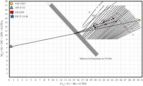
The filler metals ER 2209 DSS and ER 25.10.4L SDSS both were selected due to their chemical compositions which promote ferrite/austenite transformation. There-fore the filler metal has to keep the equilibrium between those phases during the fast cooling typical of the weld-ing process. For this work, WRC-1992 diagram modified was selected due to accuracy to predict the microstruc-ture of the dissimilar metal welding, specially the transi-tion region between the weld metal and API X-52 [15]. This diagram was developed by Kotecki for alloys with 1% Mn as is shown in Figure 2. The analysis started with the calculus of the Creq and Nieq for each alloy using the chemical composition in Table 1 and the equations proposed on this diagram.
Once this was done, the first step was to localize the coordinates corresponding to the parent metals in the diagram which are intersected by a line.
The middle point of this line could represent the join of both parent metals in equal quantities, such as in the practice, where the filler metal should be added to these alloys, which is represented by a tie line between each filler metal and the middle point. The prediction of the microstructure for the dissimilar metal welding with the filler metal ER 2209 is expected to have an 8 and 13 FN with 50% and 25% of dilution respectively, both having a primary ferrite solidification.
[image:2.595.60.537.609.721.2]The prediction of the microstructure for the dissimilar metal weld using ER 25.10.4L, showed an 18 and 10 FN
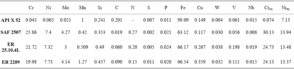
Table 1. Chemical composition of the base metal and filler metals (wt.%).
Cr Ni Mo Mn Si C N S P Fe Cu W V Nb Creq Nieq
API X 52 0.043 0.065 0.021 1 0.241 0.201 - 0.007 0.011 98.09 0.149 0.004 0.061 0.015 0.074 7.13
SAF 2507 25.86 7.4 4.27 0.42 0.353 0.019 0.27 0.002 0.021 63.12 0.117 0.030 0.056 0.008 30.13 13.94
ER
25.10.4L 21.72 7.32 3 0.509 0.49 0.060 0.20 0.005 0.024 66.17 0.267 0.038 0.198 0.019 24.73 13.48
ER 2209 19.98 7.73 4.14 1.27 0.457 0.090 0.15 0.011 0.020 66.54 0.359 0.032 0.111 0.015 24.13 13.37
Table 2. GTAW parameters.
GTAW PARAMETERS
Polarity DCEN
Welding current 110 A
Voltage 10 V
Welding speed 1.16 mm/sec
Shielding/Backing Gas Argon 100%
Interpass temperature 85°C max.
Heat input 0.75 kJ/mm
Filler metal diameter 2.4 mm
Figure 1. Microstructure of SAF 2507 and API X 52 in the as-received condition (magnification 40X).
for 50% and 25% of dilution ratio respectively, but be-low values of 42% of dilution the solidification mode is changed from ferrite plus austenite to ferrite, for that reason it could be said that ER 25.10.4L filler metal showed a better microstructural equilibrium than ER 2209 filler metal and will present a low quantity of
mar-tensite phase because of its lower percentage of manga-nese.
3.2. Dissimilar Metal Welding
To join the pipes of SAF 2507 /API X-52 was designed the single V groove preparation varying the bevel angle (60 and 90 degrees) and using the filler metal ER 25.10.4L with the aim of observing the effect of the thermal cycle promoted by the subsequent pass over the parent metals and previous passes.
To fill out the 60-deg dissimilar welding join, three welding passes were needed and five welding passes to fill out the DMW with 90-deg, as is shown in Figure 3. For each single pass the same heat input of 0.75kJ/mm was maintained. In Figure 3 is possible to observe the difference on the microstructures in function of the thermal cycles promoted by the welding passes, such effect could be noticed in the heat affected zone (HAZ) of the API X-52, where the phase transformation can be observed in function of the contrast, as well as the weld metal.
3.3. Microstructural Characterization
The microstructures in the DMW could be divided in three sections; HAZ API X-52, weld metal and HAZ SAF 2507 to observe the microstructural changes pre-sented in each zone during the root, filler and cover pass. The HAZ-API X-52 in both welds presents solid phase transformations as observed in Figure 4, being those in the 60-deg weld, more notable, where can be distinguish the upper bainite (UB) which has a characteristic of fea-thery appearance as is shown in the cover and filler pass; widmanstätten ferrite (WF) and grain boundary ferrite (GF) are present in the root pass.
On the other hand, the microstructure on the 90-deg weld shows polygonal ferrite (PF) in the root pass and the filler passes but in the cover pass shows acicular fer-rite (AF) and grain boundary ferfer-rite.
The microstructural differences between both welds are in function of the weld pass number, due to each pass submitted the parent metals to different thermal cycles, or sometimes, the parent metal is reheated [16]. This is possible to observe if both root passes are compared.
In the 60-deg weld is possible to observe the WF and PF microstructures while in the weld with 90-deg only PF is observed.
[image:4.595.59.539.404.506.2]
Figure 2. WRC-1992 diagram employed to select the filler metal.
Figure 3. DMW with different number of welding passes.
The cover pass in both welds and filler pass in the weld with 60-deg showed the effect of the fast cooling which promotes the formation of upper bainite typical of cooling rates too fast for pearlite to form, yet not rapid enough to produce martensite [17].
It is important to denote the dramatic change in the microstructure where the narrow martensite band is pre-sent in the fusion boundary between the API X-52 and the weld metal which had been predicted by the WRC-1992 diagram modified by Kotecki to accurate the prediction of martensite phase in function of the manga-nese.
These microstructural changes in the dissimilar metal welds have been studied by Nelson and Lippold who established that dissimilar weld joints present solidifica-tion pattern type II, similar to the one present in Figure 5,
where is clearly observed the suppression of normal epi-taxial growth resulting in the formation of what are called boundaries type II, which run roughly parallel to the fusion boundary formed in the solid state during weld cooling when both the weld metal and HAZ are austen-itic, allowing austenite grain growth in the fusion bound-ary. These boundaries may become sites for carbide pre-cipitation, particularly if significant carbon migration from the base metal has occurred [15].
60-DEG
FILLER
ROOT
90-DEG
[image:5.595.98.499.69.499.2]COVER
Figure 4. Transformations of solid phases in the HAZ APIX-52.
TYPE II BOUNDARIES
Figure 5. Martensite band in the fusion boundary.
The first of them could be solved if the filler metal is selected correctly in function of the chemical composi-tion which stabilizes the austenite phase with elements such as nickel and nitrogen, employing diagrams to pre-dict the microstructure resulting of the mix of parent metals and filler metal. The thermal cycles promoted by the multipass welding can origin slow cooling rates, causing a diffusional transformation of ferrite to austen-ite where can be reached a favorable equilibrium be-tween those phases. However, if the cooling is too slow in the reheated areas it could be found the precipitation of intermetallic phases [18].
[image:5.595.60.280.527.705.2]
FILLER
ROOT COVER
[image:6.595.98.499.65.504.2]60-DEG 90-DEG
Figure 6. Austenite reformation in the weld metal.
above the temperature ferrite solvus, ferrite grain growth occurs since there is no second phase (austenite) or pre-cipitates to inhibit such growth.
The multipass welding could maintain the parent metal above the ferrite solvus promoting the growth of the fer-rite grains. During the cooling, when the temperature is below the ferrite solvus temperature, austenite will nu-cleate and grow and the precipitates will reform.
The ferrite-to-austenite transformation for a given al-loy is controlled by the cooling rate. With higher cooling rates as is shown in the 60-deg weld where is possible to observe that the austenite reformation is suppressed and resulting in higher ferrite contents in the HAZ. The de-gree of precipitation is also a function of the cooling rate [15].
3.4. Mechanical Properties
The dissimilar welding joints were subjected to tensile test with the aim of knowing the ultimate strength and the behavior of the joint. Two tensile samples with stan-dard dimensions were performed for each joint, obtain-ing values of ultimate strength of 541 and 533 MPa for the 60-deg DMW and 531 and 556 MPa for the 90-deg DMW.
FILLER
ROOT COVER
[image:7.595.93.497.71.500.2]60-DEG 90-DEG
Figure 7. Heat affected zone in the SAF 2507.
of phases was adequate for that reason all the samples showed good performance in the root and face bends.
The microhardness Vickers was performed with the aim of knowing the effect of each phase in the dissimilar joint, as is shown in Figure 8.
In Figure 8 is possible to notice the effect of the mar-tensite band on the increase of the hardness in the fusion boundaries followed by a hardness decreasing in the ad-jacent zone in both dissimilar welds which could be at-tributed to the phase transformations in that zone. Al-though the decrease of the hardness in that zone, the hardness values are higher than the hardness in the base metal API X-52.
4. Conclusions
The selection of the filler metal employing the WRC-1992
modified by Kotecki demonstrated to be accurate for dissimilar metal welding due to it can predict the mart-ensite boundary and the microstructural balance between ferrite and austenite using the ER 25.10.4L filler metal which the chemical composition has low percentage of manganese and molybdenum but high percentage of ni-trogen. The effect of the filler metal is clearly observed in the microstructure of the weld metal and HAZ where high austenite phase was obtained, but is important to consider the effect of the thermal cycles of the multipass weld which promotes the austenite reformation.
The HAZ of the API X 52 shows different transforma-tion typical of that alloy when they are submitted to thermal cycles evolved a rapid cooling, which is the case of upper bainite phase.
Figure 8. Microhardness profiles of the dissimilar metal welding.
the HAZ. The martensite showed in the fusion bounda-ries is formed when both alloys at high temperature pre-sent austenite phase and some atoms of carbon starts to diffuse from the API X-52 (with high concentration) to the weld metal (with lower concentration). Nevertheless some atoms during the cooling find the preferential place in the interface, which promotes the transformation to martensite phase. On the other hand the HAZ of the SAF 2507 SDSS is represented by the reformation of austenite phase in the zones where ferrite solvus temperature was reached, showing again the effect of the filler metal composition and thermal cycles of multipass welding.
The dissimilar welding joint showed higher resistance than the API X-52 base metal in the tensile test and good performance in the bend test, showing the soundness of the joint. The results demonstrated that the filler metal
contributes to the austenite formation which gives those characteristics of behavior. The microhardness showed not only the clear difference between the alloys but also the effect of the phases, as the martensite phase.
6. References
[1] PEMEX, “Tubería de acero para recolección y transporte de hidrocarburos,” NRF-001-PEMEX-2007 México, 2007.
[2] J. J. Perdomo, J. J. Gonzalez and A. Viloria, “Corrosion of API 5L and X52 in Crude Oil/Water/Gas Mixtures,”
Materials Performance, Vol. 39, No. 2, 2000, pp. 76-79.
[3] PEMEX, “Sistema de protección del ducto ascendente en la zona de mareas y oleaje,” NRF-177-PEMEX-2007, México, 2007.
[4] O. Smuk, H. Hanninen and J. Liimatainen, “Mechanical and Corrosion Properties of P/M-HIP Super Duplex Stainless Steel after Different Industrial Heat Treatments as Used for Large Components,” Materials Science and Technology, Vol. 20, No. 5, 2004, pp. 641-644.
[5] F. Elshawesh, N. Elahresh and A. Elhoud, “Effect of Sigma Phase on Pitting Corrosion 22-5 Duplex Stainless Steel,” British Corrosion Journal, Vol. 33, No. 4, 1998,
pp. 285-287.
[6] Y. H. Lee, K. T. Kim, Y. D. Lee and K. Y. Kim, “Effect of W Substitution on Sigma and Chi Phase Precipitation and Toughness in Duplex Stainless Steels,” Material Science and Technology, Vol. 14, No. 8, 1998, pp. 757-
764.
[7] R. Francis, “Coupling of Super Duplex Stainless Steel and Cast Nickel-aluminium Bronze in Sea Water,” Brit-ish Corrosion Journal, Vol. 34, No. 2, 1999, pp. 139-145.
[8] A. A. El-Yazgi and D. Hardie, “Effect of Heat Treatment on Susceptibility of Duplex Stainless Steel to Embrittle-ment by Hydrogen,” Materials Science and Technology,
Vol. 16, No. 5, 2000, pp. 506-510.
[9] V. Amigo, V. Bonache, L. Teruel and A. Vicente, “Me-chanical Properties of Duplex Stainless Steel Laser Joints,” Welding International, Vol. 20, No. 5, 2006, pp.
361-366.
[10] V. V. D. Mee, H. Meelker and R. V. D. Schelde, “How to Control Hydrogen Level in (Super) Duplex Stainless Steel Weldments Using the GTAW or GMAW Process,”
Welding Journal, Vol. 78, 1999, pp. s7-s14.
[11] E. J. Barnhouse and J. C. Lippold, “Microestruc- ture/Property Relationships in Dissimilar Welds Between Duplex Stainless Steels and Carbon Steels,” Welding Journal, Vol. 77, No. 12, 1998, pp. s477-487.
[12] H. Hemmer and O. Grong, “A Process Model for the Heat-affected Zone Microstructure Evolution in Duplex Stainless Steel Weldments: Part I. The Model,” Metallur-gical and Materials Transaction A, Vol. 30A, No. 11,
1999, pp. 2915-2929.
Dissimilar Weld Metals, Part 1-Nucleation and Growth,”
Welding Journal, Vol. 78, No. 10, 1999, pp. s329-s337.
[14] D. J. Kotecki, “A Martensite Boundary on the WRC 1992 Diagram Part 2: the Effect of Manganese,” Welding Journal, Vol. 79, No. 12, 2000, pp. s346-s354.
[15] J. C. Lippold and D. J. Kotecki, “Welding Metallurgy and Weldability of Stainless Steels,” Jhon Wiley & Sons, New Jersey, 2005.
[16] H. Granjon, “Fundamentals of Welding Metallurgy,” Abington Publishing, Cambridge, 1991.
[17] H. K. D. H. Badeshia and R. W. K. Honeycombe, “Steels,” 3rd Edition, Butterworth-Heinemann, Oxford, 2006.
[18] S. Henrik and R. Sandström, “Austenite Reformation in the Heat-affected Zone of Duplex Stainless Steel 2205,”
Materials Science and Engineering A, Vol. 418, No. 1-2,
2006, pp. 250-256.
[19] K. Bekker, “Practice in Welding Duplex and Super Du-plex Stainless Steel Worldwide,” Welding in the World,