iBusiness, 2010, 1: 29-41
doi:10.4236/ib.2010.21003 Published Online March 2010 (http://www.SciRP.org/journal/ib)
A Systematic Framework of Equipment
Maintenance and Service with Application to Wire
Bonder
Ren-Jung Chang1, Yu-Tsang Hsieh2, Eric Chang3
1Department of Mechanical Engineering, National Cheng Kung University, Taiwan, China; 2Customer Operations, Kulicke and Soffa
Asiapac Inc., Taiwan, China; 3Narmo International Inc., Alberta, Canada. Email:rjchang@mail.ncku.edu.tw, ahsieh@kns.com, eric@narmo.com
Received August 11th, 2009; revised October 2nd, 2009; accepted November 17th, 2009.
ABSTRACT
A systematic framework for the maintenance and service of equipment is developed and proposed. The framework con-sists of a system of equipment failure analysis, methods, process, and activities, and a procedure in maintenance and service. With axiomatic design mapping, the maintenance procedure is constructed by integrating value engineering, quality function deployment, mechatronics engineering, technique from R&D and supplier, and Taguchi method. The maintenance and service of a wire bonder machine, K&S (Kulicke and Soffa) Maxμm Plus, in the first bond failure is employed for illustration.
Keywords: Systematic Framework, Maintenance, Service, Wire Bonder, Failure Modes, Mechatronics, Axiomatic De-sign, Taguchi Method
1. Introduction
Since the first development of ball bonding technique by the Bell Laboratories, more than five trillion wires have been bonded onto various semiconductor devices rou-tinely every year [1]. Today, with the increasing equip-ment and workload in a semiconductor business, cus-tomers are relying on suppliers to provide efficient and effective maintenance and service. The importance of maintenance function and its management has grown rapidly. As a matter of fact, some research efforts have been undertaken on the maintenance related issues in the semiconductor business through out the years [2,3]. For example, integration of failure analysis in microelectron-ics manufacturing process was proposed for cost reduc-tion [2]. In the research area, many research efforts have been undertaken on the field of maintenance manage-ment. The objectives cover the fields ranging from opti-mization models, maintenance techniques, scheduling, performance measurement, information systems to poli-cies [4]. In the literature review [4], most of the resear- ches have been established on developing general meth-ods for the development and operation of maintenance system. However, methods for the maintenance and ser-vice of equipment in the troubleshooting of system fail-ure and assuring production quality to satisfy customer’s
needs are seldom published.
Maintenance engineering and service operation allow customers to have on-going and routine access with ex-perienced engineering experts for minimizing the effort of maintenance management. In addition, it allows customers to focus on their core competencies and areas of individual specialty. Maintenance is an engineering decision and as-sociated actions for the optimization of specified capabili-ties [5]. A service is to perform an action for customer to keep a product in good operating condition. The benefits of maintenance procedures in manufacturing environment will not only optimize machine reliability to reduce pro-duction costs but also improve product quality to increase yield. The service operation enhances the technical over-sight of specialized engineering operations at a fraction of the required cost to maintain the performance in-house. Development of a systematic engineering method for effi-cient and effective maintenance and service of semicon-ductor equipment should provide large returns in produc-tivity for a semiconductor fabrication business.
A Systematic Framework of Equipment Maintenance and Service with Application to Wire Bonder
30
ledge of equipment. Then, the framework is employed for troubleshooting the first bond failure and mainte-nance service. Finally, the contribution by the present approach on the maintenance and service of equipment is concluded.
2. Systematic Framework of Maintenance
and Service
Maintenance activities in engineering service will in-crease machine utilization and improve productivity. There are several activities such as Failure Mode and Effects Analysis (FMEA), troubleshooting, and process optimization involved in the maintenance and service of equipment. In this section, a systematic framework is developed for providing an efficient and effective main-tenance and service.
2.1 Engineering System of Failure Analysis
Engineering maintenance and service usually involve a complex combination of resources. A system engineering method is required to manage engineering resources to fulfill customer’s needs [6]. For providing maintenance service to customers, qualified engineers are to be trained through laboratory and field practice. Engineer training usually includes practicing technical skill, writing reports, and studying ethics. Engineering measuring and testing techniques regarding semiconductor equipment are re-quired and built on the knowledge among a production field. All related information in maintenance practice is to be documented to improve engineer skill and attitude. In failure diagnosis, failure criteria are required a priori to classify operating status. For providing an optimal solution in reducing the failure probability over time, the analysis of the value in industrial environment for the operation of equipments will be tracked and controlled for every aspect of routine and non-routine equipment maintenance.
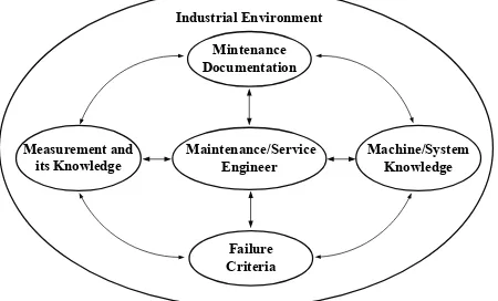
For the system involved in failure analysis and main-tenance, the objective is to optimize maintenance func-tion and servicing cost to satisfy customer’s needs. For system engineering management, the system environ-ment and components are to be identified. The activities of equipment failure analysis and maintenance are deemed to be operated in an industrial environment. The industrial environment may include human and material resources, industrial standards and technologies, political, economic and social factors, and international involve-ment [6]. For the system components involved in the activities, five components can be identified as Mainte-nance/Service Engineer, Machine/System Knowledge, Measurement and its Knowledge, Failure Criteria, and Maintenance Documentation. In order to operate main-tenance system, all activities are to be relied on mainte-nance/service engineer. Therefore, the component of
Maintenance/Service Engineer will interact with all the other four components. From the above analysis, a sys-tem model of equipment failure analysis and mainte-nance for engineering service is constructed and pro-posed as depicted in Figure 1.
2.2 Methods, Process, and Activities
A scheme to integrate various methods in maintenance process is constructed for machine diagnostics and proc-ess optimization of semiconductor equipment. Several related techniques and methods to be integrated for real-izing the system of equipment failure analysis and main-tenance in Figure 1 will be briefly introduced.
Value engineering provides a measure of value for the purpose of maintenance and service of semiconductor equipment. Value can be defined as function over cost [6]. The value of maintenance and service for different failure modes needs to be evaluated. The ultimate goal of the maintenance and service support in the fabrication industries is to increase the net value by reducing the cost, and increasing customer’s acceptance during the equip-ment’s life cycle.
The conversion from customer’s needs to functional requirements in equipment development is an essential issue in a semiconductor business. A systematic method of Quality Function Deployment (QFD) can be applied quantitatively to solve the conversion problem. In realiz-ing QFD, a central element called House of Quality is usually employed. The success of QFD relies on the de-tailed investigation of the customer’s needs and the evaluation of the markets. The initial tasks in QFD are to acquire market needs by listening to the voice of cus-tomer, sorting the needs, and prioritizing the needs nu-merically. In reliability engineering, the attempt of in-troducing an integrated usage of QFD and FMEA has been undertaken by several researchers [7].
A machine as a system can be decomposed into many sub-systems for engineering operation and testing. In the
Maintenance/Service Engineer Measurement and
its Knowledge
Machine/System Knowledge Mintenance
Documentation
[image:2.595.309.534.550.686.2]Failure Criteria Industrial Environment
A Systematic Framework of Equipment Maintenance and Service with Application to Wire Bonder 31
decomposition of semiconductor equipment, it is essen-tial to understand the equipment’s principle and mecha-nism in operation. The design and implementation of the semiconductor equipment relies on the integration of precision mechanical engineering, electrical control, and system thinking. According to the definition of mecha-tronics by EEC [8], the technique and the knowledge of semiconductor equipment is classified as a discipline of mechatronics. With the knowledge of mechatronics in semiconductor equipment, failure analysis and mainte-nance can be undertaken by engineers in service.
Semiconductor equipment is designed and imple-mented through precision engineering. In the field of precision design, Suh [9] identified two design axioms from abstracting common mapping domains of a body of precision designs, including products, processes, and systems. The foundation of axiomatic design is to con-struct design mappings in the forward engineering. The design mappings are from Customer Attributes (CAs) to Functional Requirements (FRs), then from FRs to Design Parameters (DPs) and finally from DPs to Process Vari-ables (PVs). Recently, the design method has been inte-grated with other methods for different applications. For example, a design method to integrate the axiomatic de-sign and robust dede-sign was developed for assuring six-sigma quality in product [10]. In addition, some thoughts were proposed on potential integration of axio-matic design with quality tools to enhance product de-velopment process [11].
For a semiconductor fabrication process, minimizing the process variations is the fundamental objective in achieving the optimal machine operation. There has long been a desire to increase the yield by utilizing an electri-cal or mechanielectri-cal in-process quality control system. En-gineers working on designing quality into products and processes should be provided with a tool available for the experimental design in the field tests. Taguchi has de-veloped a robust method for improving the quality of Japanese products with great success [12]. Taguchi’s method is a robust method for improving productivity so that high-quality products can be produced at low cost
[13]. The robust method, in essence, is to utilize a Sig-nal-to-Noise (S/N) ratio to estimate and assure the mini-mum variability in product quality.
Maintenance engineers need to have full knowledge about machine failure in maintenance service. In fabrica-tion industry, a method of FMEA provides a structured approach to analyze the root causes of failure, and as-sesses the potential failure modes of a process and their causes in risk prevention measures [6,14]. In utilizing FMEA, an integral part is to calculate Risk Priority Number (RPN) for ranking and assessing risk of failure modes [14]. The RPN is used to prioritize items of causes that require additional quality planning or action. The items with the highest RPN and severity ratings usually will be given first consideration. However, the priorities ranking by RPN may not always reflect the true concerns in maintenance management [15].
In the operation of semiconductor equipment, the op-erational process and equipment setting in production are usually relied on the techniques from R&D and supplier. The operational techniques usually are to be trained through laboratory and field practice.
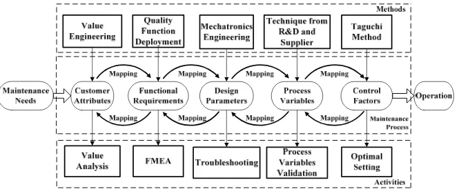
In the applications of precision engineering to the semiconductor industry, there should also be an efficient and effective maintenance system for providing high performance and quality operations at a reasonable cost. In considering that axiomatic design can be used as the foundation in designing semiconductor equipment, a systematic method through axiomatic design mapping is proposed for engineers to solve the maintenance prob-lems. By integrating the engineering methods mentioned in the previous paragraphs along with the forward and inverse mappings in axiomatic design, a scheme to inte-grate various methods in maintenance process for ma-chine diagnostics and process optimization of semicon-ductor equipment is constructed and depicted in Figure 2.
[image:3.595.134.468.568.705.2]In Figure 2, the maintenance needs are initially raised by the customer. In proceeding maintenance process, the value and worth of maintenance will be analyzed and evaluated. The value analysis requires the mapping be-tween the CAs and FRs. The FRs can be deployed and
Study of Green Behavior with a Focus on Mexican Individuals 32
defined based on the analysis of quality function. By analyzing and evaluating the maintenance needs and FRs, CAs are determined by using the method of value engi-neering. In proceeding the analysis of FRs in mainte-nance, FMEA is undertaken to obtain causes and effects of failure modes. For semiconductor equipment, various components are mutually affected regarding the behav-iors of machine and its performance. By utilizing mecha-tronic engineering, the forward mapping from the FRs to DPs is analyzed to give the reverse mapping of DPs that affect the FRs. With the mapping from the FRs to DPs, the DPs which affect FRs can be verified in trouble-shooting during maintenance. With the DPs, a mapping from the DPs to PVs for semiconductor equipment can be constructed. The PVs will affect the variations of DPs in equipment during the life cycle of equipment opera-tion. For the PVs, some PVs related to fabrication proc-esses which are sensitive to disturbances will be involved in quality problems. By assuming a set of PVs which may affect the quality specifications, laboratory experi-ments can be carried out by supplier or through R&D for identifying the key PVs. The key PVs which are defined as Control Factors (CFs) are employed for assuring pro-duction quality. In propro-duction, an important aspect of quality in setting CFs is to achieve robustness. Since the issue of robustness cannot be addressed until noise fac-tors are given in an environment, designed experiments by Taguchi method are utilized to find out the optimal setting of CFs for minimizing product variance during equipment operation.
2.3 Procedure
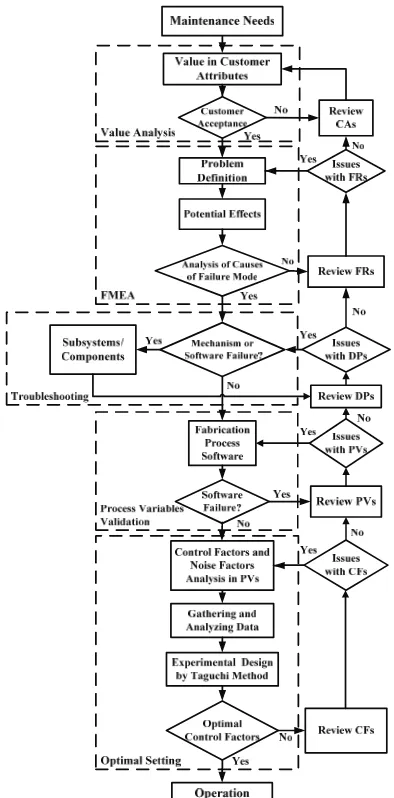
Under the diagram constructed in Figure 2, a procedure for realizing maintenance and service will be developed. In the maintenance procedure starting from Maintenance Needs to Operation, there are five activities associated with the mapping domains, respectively. The five activi-ties including Value Analysis, FMEA, Troubleshooting, Process Variables Validation, and Optimal Setting will proceed with the following steps.
1) Value Analysis
At first, maintenance needs are initiated by the customer. Therefore, from the initiation of maintenance needs, CAs will be reviewed and revised and the value in CAs will be evaluated iteratively. If the maintenance service is valuable for proceeding the troubleshooting and/or proc-ess optimization, the FMEA will be undertaken to ana-lyze the root causes of failure modes.
2) FMEA
In proceeding with the FMEA, the failure problem will be defined in operation environment. In addition, infor-mation of potential effects of failure and risk factor rating are analyzed and documented. The analysis of failure modes and their causes can be inferred by identifying the failure problem, reviewing FRs, and the corresponding
DPs iteratively. 3) Troubleshooting
After FMEA, field tests are undertaken for troubleshoot-ing. The failure due to mechanism or system software in semiconductor equipment will be tested first. The trou-bleshooting is undertaken by iterating test and check in order to resolve any issues of DPs in the subsystems or components.
4) Process Variables Validation
If the equipment is functionally correct, the equipment will be controlled and tested by setting PVs in fabrication process software. The operation of equipment will be validated iteratively by reviewing and revising PVs to make sure that PVs are correct and no failures occur in the fabrication process software.
5) Optimal Setting
If the equipment operates correctly under the control of fabrication process software, then experimental tests will be applied for process optimization. By analyzing the CFs and noise factors in PVs and testing the CFs in fabrication process software, Taguchi method is applied through re-viewing CFs iteratively for obtaining optimal CFs.
The maintenance and service procedure is completed after setting the optimal CFs. The implementation of the maintenance and service procedure will indicate that the failure has been resolved and the machine performance is robust in operation. From the above analysis and referring to Figure 2, a procedure of maintenance and service is proposed and complied as shown in Figure3. From Fig-ure3, it is observed that optimal and robust operational quality can be obtained by adjusting CFs as long as there are no issues with PVs. However, if better performance improvement is required, further maintenance service can be undertaken through reviewing PVs, returning PVs to DPs, from DPs to FRs, or even from FRs to CAs for ana-lyzing service value to satisfy customer’s needs.
3. Wire Bonder System
3.1 Mechatronics Structure
Mate-A Systematic Framework of Equipment Maintenance and Service with Mate-Application to Wire Bonder 33
rial Handling System includes driving components, motion executing components, and sensing components. XY-Ta-ble Assembly includes driving components, motion exe-cuting components, and sensing components. Equipment Network and Software includes the network communica-tion components, operating system components and also the application software components. The Equipment Network which is constructed by employing Semiconduc-tor Equipment Communication Standard (SECS), General Equipment Model (GEM), and High Speed Message Se-ries (HSMS) follows the Semiconductor Equipment Ma-terials International (SEMI) standards. From the analysis, a three levels structure diagram is depicted as shown in
Figure 4. The first level is functional subsystems. The second level is components of the corresponding subsys-tems. The third level is functional elements correspond-ing to each component. By utilizcorrespond-ing the diagram of Fig-ure4, the mapping of a wire bonder from FRs to DPs
can be analyzed and documented as machine knowledge in Figure1.
3.2 Knowledge Structure
A wire bonder with five modules of subsystem is re-quired to satisfy functional requirements. The mapping between FRs and DPs which satisfies a decoupled mod- ule design is given by (1) with weighting Aij as
11 21 22 31 32 33 41 42 44
51 52 55
0 0 0 0
1 1
0 0 0
2 2
0 0
3 3
0 0
4 4
0 0
5 5
A
FR DP
A A
FR DP
A A A
FR DP
A A A
FR DP
A A A
FR DP
(1)
The FRs in (1) are listed as
FR1: Provides command control and electronic control of equipment
FR2: Affords bonding motion for each recipe selected FR3: Recognizes the image of materials by operator and machine
FR4: Provides material transportation capabilities FR5: Maintains bonding table movement over the working area
The DPs for the subsystems in (1) are listed as
DP1: Signal, motion, and power control in Console System
DP2: Wire bonding is accomplished by mechanisms and controls of Bond Head Assembly
DP3: Targeting of devices is accomplished by Vision System
DP4: Move the materials for bonding demands as Ma-terial Handling System
DP5: XY-Table Assembly moves bonding mecha-nisms over the working space
3.3 Knowledge Representation
The knowledge representation constructed by axiomatic mapping can be derived from decomposition and zigzag mapping [9]. Only two levels in the representation of equipment knowledge are given in the following list. The lower levels of FRs and DPs will be given in the appendix.
1) Console System
FR1-1: All subsystems to be under control DP1-1: Monitor and control system FR1-2: Supply energy resources DP1-2: Power system
FR1-3: Control the operation of machine DP1-3: Human/machine interface
FR1-4: Software operations and data storage DP1-4: Storage system
FR1-5: Air supply and control DP1-5: Pneumatic system
[image:5.595.73.270.301.700.2]FR1-6: Feed wire for automatic bonding DP1-6: Wire feed system
Study of Green Behavior with a Focus on Mexican Individuals 34
Wire Bond Machine Assembly
Hum an/ M achi n e In terf ace Bond Head Assembly Material Handling System
Vision System XY-Table
Assembly Equipment Network El ectr oni c C on so le P n eu m ati c Sy ste m E le vat or Me ch an is m D et ecti on Se ns or Z-A xi s Serv o Sy stem Wi re C la m p U lt ras on ic G en er at or O p tome ch an ic al Me ch an is m Imag e Pr oc essi n g Sy stem Li ghti ng Sy st em X -A xi s S erv o Sy stem Y -A xi s S erv o Sy stem T abl e M echa n is m Ph ys ic al Ne two rk Mo us e Ke yb oa rd P owe r Su ppl y Bac kpl ane PC B Co ol in g F ans F eed ing M ec han ism T ens io ne r W ork hol der Vac uum C oolin g S yste m Pu ller A ss em b ly In dexe r/Ej ecto r ass em b ly He at Bl oc k H eater s/T herm oco upl es R ails A ss em b ly In pu t Ele vato r Ou tpu t El ev at or O pti cal M ete r Tab le B ase L imi t Se nso r El ect ro ni c F la m e Off Software Console System Tran sdu cer EF O W an d El ec tr od e E F O Elec tron ic C ircu it P iezo elect ric B im orph Arm B ase Z S erv o Mo to r Z L in k/ Ba se Z En cod er/A m p lifier X S erv o Mo to r X En cod er/A m p lifie r Y S erv o Mo to r Y En cod er/A m p lifie r Wo rk L ig h t Il lum ina tive Asse m b ly CC D C ame ra s Opt ic al Bas e SE C S/G E M /H S M S Ne twor k A dap ter Mo ni to r Opera ti ng S ys tem A ppl ic at io n So ftw ar e B on d S ite D iffu ser Bo nd I nt eg ri ty Tes t Sy stem F lex ure Bea ri n g El ec tr on ic S yst em F le xu re B ear in g A ss emb ly P ow er Sy ste m S tor ag e S yst em Em erg enc y sto p Pow er f use Ha rd D is k/ F lo pp y/ CD M obi le S tora ge D evic es Dr iv er K ern el W ire Bo nd S oft ware Da ta ba se R esou rce M an age m en t G raph ical Use r In terfa ce Ca bl es Ca bl e SEMI St anda rds G en era tor
Equipment Network and Software
Wi re F eed Sy stem Tr ans po rti ng Me ch an is m Hea ter A ss em bl y C lam pi n g As se mb ly Cl am p/ H ol d Do wn Me ch an is m Equipment Hardware
Figure 4. Structure diagram of a wire bonder
The following components are decomposed to be unique and independent and will be used as the basis for formu-lating DPs which are corresponding to FRs, respectively. The decomposition is undertaken for the Bond Head As-sembly.
2.1 Electronic Flame Off (EFO)
FR2-1: Discharge for wire ball formation DP2-1: EFO assembly
2.2 Wire Clamp
FR2-2: Feed and hold wire DP2-2: Wire clamp assembly 2.3 Ultrasonic Generator (USG)
FR2-3: Generate and transmit ultrasonic energy DP2-3: USG system
2.4 Z-axis Servo System
FR2-4: Bond head positioning and force control DP2-4: Z-axis servo system
2.5 Bond Integrity Test System (BITS) FR2-5: Detection of bonding outcome DP2-5: Bond integrity test system 2.6 Flexure Bearing Assembly FR2-6: Provide rotational movement DP2-6: Flexure bearing
3) Vision System
The decomposition is undertaken for the Vision Sys-tem with DP3 corresponding to FR3.
FR3-1: Clear image
FR3-2: Image acquisition with high speed FR3-3: Focus range and field of view extension DP3-1: Illumination and image acquisition system DP3-2: Image processing system
DP3-3: Optomechanical extension mechanisms 4) Material Handling System
The decomposition is undertaken for the Material Han-dling System with DP4 corresponding to FR4.
FR4-1: Carry the materials in the bonding cycle FR4-2: Fix the materials on the bond site FR4-3: Provide the working temperature
FR4-4: Prevent materials damaged during transporta-tion
FR4-5: Handle magazines during the bonding opera-tion
DP4-1: Transporting mechanism DP4-2: Clamping assembly DP4-3: Heater assembly DP4-4: Detection sensor DP4-5: Elevator mechanism 5) XY-Table Assembly
The decomposition is undertaken for the XY-Table Assembly with DP5 corresponding to FR5.
FR5-1: I/O density of IC chip become higher
FR5-2: Chip dimension and the bond pad pitch be-come smaller
DP5-1: High speed and steady XY-servo system DP5-2: XY-Table mechanism
4. First Bond Failure and Maintenance
Study of Green Behavior with a Focus on Mexican Individuals 35
Figure 5. First bond failure analysis
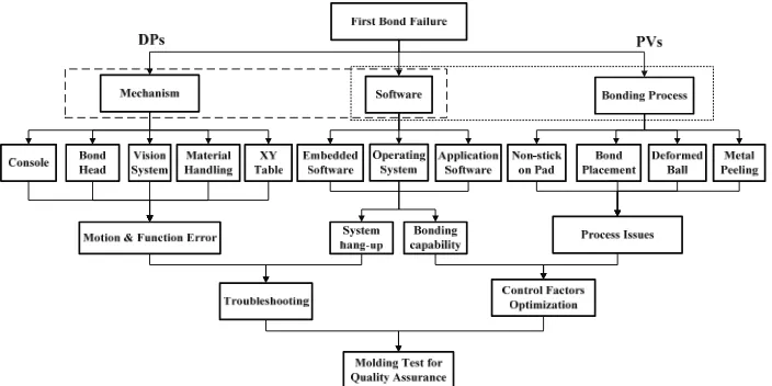
The analysis of the first bond failure through DPs and PVs by the present approach is shown in Figure5. By utilizing both engineering experience and documented equipment knowledge, the results of wire bonder failure modes corresponding to DPs are analyzed and obtained. In addition to these information and knowledge, the im-plementation results still rely on experience of measure-ments, tests, record of FRs, and customer feedback.
4.1 Value Analysis
Value is the first consideration by customers in needing maintenance as shown in Figure 3. In considering the CAs in needing maintenance service, a maintenance task [6] including task description, elapsed time, estimated cost for achieving specified functional performance will be proposed. With the proposed maintenance task analy-sis, the maintenance value can be justified and managed by customers. By assuming that the proposed service can satisfy CAs, the maintenance on the first bond failure will be undertaken by following Figure3 through FMEA, Troubleshooting, Process Variables Validation, and Op-timal Setting.
4.2 FMEA
In wire bonder industry, the performance of first bond operation can be qualified by employing the tests of ball size, ball shear, intermetallic compound, and etching. For the first bond operation, four common failure modes as Non-stick on Pad, Bond Placement, Deformed Ball, and Metal Peeling are identified as shown in Figure5.
1) First Bond Failure Modes
1.1 Failure mode Ⅰ: Non-Stick on Pad
Ball shear stress calculated with the apparent bonded area will provide a conservative underestimation of the quality of the gold-to-aluminum intermetallic bond line. This failure mode means a bond ball lift out of pad.
1.2 Failure mode Ⅱ: Bond Placement
The accuracy of bond position must be controlled for the bond placement under the bond pad size.
1.3. Failure mode Ⅲ: Deformed Ball
An ideal bond ball should have the best bond line quality with ball size proper for the bond pad.
1.4. Failure mode Ⅳ: Metal Peeling
Bond pad metal peeling is recognized as a serious problem of bonding ability and ball bond reliability in electronic packaging industry.
2) RPN Analysis
By analyzing the RPN value of the first bond failure, a decision making on the priority in maintenance can be justified and managed. The RPN for four failure modes is evaluated. The RPN is calculated as a mathematical product of the numerical ratings of severity, probability of occurrence, and detection likelihood given by
, , ,
i j k k i j k k i j k k i j k,
A s r m e n f (2) In (2), the indices i, j, k represent the sub-system, the component of the sub-system, and the failure mode, re-spectively. The Ai-j,k is the RPN for each DPs of the
fail-ure mode k. The sk is a severity rating for failure mode k
and the ri-j,k is a severity rating for each DPs of the failure
mode k. The mk is a probability rating for failure mode k
and the ei-j,k is a probability rating for each DPs of the
failure mode k. The nk is a detection rating for failure
mode k and the fi-j,k is a detection rating for each DPs of
A Systematic Framework of Equipment Maintenance and Service with Application to Wire Bonder
36
,
, ,
,
/
i j k i j k i j k i j
B A
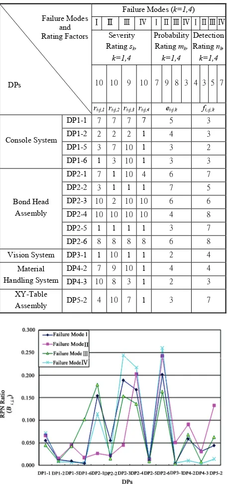
A (3) [image:8.595.59.287.221.708.2]The results of RPN ratio for the four kinds of failure modes of the first bond process are to be computed by utilizing (2) and (3) with data from Table 1.The results of RPN ratio with respect to DPs for the four failure modes are calculated and obtained as shown in Figure 6. From Figure6, the optimal decision and associated ac-tions can be inferred. In Figure6, DPs with higher RPN Table 1. Rating factors for evaluation of RPN in the first bond failure modes
Failure Modes (k=1,4)
Ⅰ Ⅱ Ⅲ Ⅳ ⅠⅡ Ⅲ ⅣⅠⅡⅢⅣ Severity
Rating sk,
k=1,4
Probability Rating mk,
k=1,4
Detection Rating nk,
k=1,4
10 10 9 10 7 9 8 3 4 3 5 7 Failure Modes
and Rating Factors
DPs
ri-j,1 ri-j,2ri-j,3 ri-j,4 ei-j.k fi,-j,k DP1-1 7 7 7 7 5 3 DP1-2 2 2 2 1 4 3 DP1-5 3 7 10 1 3 2 Console System
DP1-6 1 3 10 1 3 3 DP2-1 7 1 10 4 6 7 DP2-2 3 1 1 1 7 5 DP2-3 10 2 10 10 6 6 DP2-4 10 10 10 10 4 8 DP2-5 1 1 1 1 3 7 Bond Head
Assembly
DP2-6 8 8 8 8 6 8 Vision System DP3-1 1 10 1 1 2 4 DP4-2 7 9 10 1 4 4 Material
Handling System DP4-3 10 8 3 1 2 3 XY-Table
Assembly DP5-2 4 10 7 1 3 7
Figure 6. RPN ratio of maintenance for first bond process
ratio for each failure mode are assumed to be more im-portant and given higher maintenance priority than those having a lower RPN ratio. From Figure 6, it is observed that the highest priority for failure mode Ⅰ, Ⅱ, and Ⅳ is DP2-6. The DP2-6 is a flexure bearing. For failure mode
Ⅲ, the highest priority is DP2-1. The DP2-1 is an EFO assembly. The priority distribution of RPN ratio for the components of wire bonder provides enough information for maintenance engineers to realize the effects of failure modes.
4.3 Troubleshooting
If there is no failure in the Software of Figure 5, the causes for the failure of DPs in the mechanism of the wire bonder are obtained by utilizing the knowledge rep-resentation and engineering experience in Figure 5 to give the following list.
1) Console System: failure related to mode Ⅰ, Ⅱ, and Ⅲ
DP1-1: Monitor and control system DP1-2: Power system
DP1-5: Pneumatic system DP1-6: Wire feed system
2) Bond Head Assembly: failure related to mode Ⅰ,
Ⅱ, Ⅲ, and Ⅳ
DP2-1: EFO assembly DP2-2: Wire clamp assembly DP2-3: USG system
DP2-4: Z-axis servo system DP2-5: Bond integrity test system DP2-6: Flexure bearing
3) Vision System: failure related to mode Ⅱ
DP3-1: Illumination and image acquisition system 4) Material Handling System: failure related to mode
Ⅰ, Ⅱ, and Ⅲ
DP4-2: Clamping assembly DP4-3: Heater assembly
5) XY-Table Assembly: failure related to mode Ⅱ and
Ⅲ
DP5-2: XY-Table mechanism
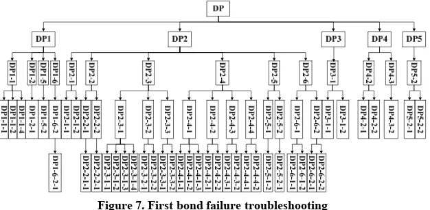
From the analysis of DPs in the knowledge representa-tion, causes analysis, and utilizing engineering experi-ence for the first bond failure, the detail troubleshooting result of DPs is obtained as shown in Figure 7. The lower levels of DPs in Figure7 are referred to Appendix. In Figure7, the DPs are employed as DP1 for Console System, DP2 for Bond Head Assembly, DP3 for Vision System, DP4 for Material Handling System, and DP5 for XY-Table Assembly.
4.4 Process Variables Validation
Study of Green Behavior with a Focus on Mexican Individuals 37
Figure 7. First bond failure troubleshooting
is met by the production standard. Bonding material and bonding temperature are fixed. A gold wire of 20μm is used. The temperature of bond-site area is 150 . Sui℃ t-able capillary is chosen on K&S Maxμm Plus wire bonder. From the results obtained for the process study, the feedback of quality analysis responds the relation-ships between PVs and DPs. The PVs related to the process of the first bond failure are validated to give
PV1-1: Signal to electronic devices PV1-2: Different rating of supply voltages PV1-3: Different input commands
PV1-4: Different program storage selections PV1-5: System flow rate adjustments PV1-6: Wire feed flow rate adjustments
PV2-1: Adjustment of EFO firing time and control current
PV2-2: Adjust wire pullout
PV2-3: Setting ultrasonic power utilization
PV2-3-1: Setting USG applied amplitude and fre-quency
PV2-3-2: Capillary tube and transducer installation adjustment
PV2-3-3: Setting USG in bonding process PV2-3-3-1: Setting pre-bleed USG PV2-3-3-2: Setting bonding USG
PV2-4: Variables in Z-axis motion on bonding time and force
PV2-4-1: Bonding force PV2-4-2: Z-axis position PV2-4-3: Bonding time
PV2-4-4: Capillary searching speed PV2-5: Signal of bonding processes
PV3-1: Adjust optical limit and select image setting PV3-2: Set parameters of image processing
PV3-3: Select different cameras and magnifications PV4-1: Material transportation variables
PV4-2: Clamping compensation adjustments PV4-3: Variables of bonding temperature PV4-4: Set up sensor sensitivity
PV4-5: Adjust elevator parameters PV5-1: Adjust XY-axes motion and speed
PV5-2: Adjust XY-motion accuracy
4.5 Optimal Setting
Minimization of the variation of the bonding process is to achieve high yield in production. The specifications of bond ball can be set according to customer’s require-ments. Optimization of CFs for assuring bond ball qual-ity is undertaken by employing Taguchi method [12,13]. In the Taguchi’s experimental tests, the quality target is called signal and the variation in the target is called noise.
1) Quality Characteristics
For the first bond process, the quality requirements of ball size and ball shear are specified. The quality target of ball size, as tri-axial appearances, is given as Nomi-nal-the-Best. The quality target of ball shear force is given as The-Larger-the-Better. The shear force is ob-tained by utilizing shear strength, as shear force per unit area, multiplied by the estimated area. The quality speci-fications for the first bond in the experiment are given as
1.1. Quality Targets:
a. Ball size: Nominal-the-Best
Ball X & Ball Y (Plane of bond pad)-40μm +/-2μm
Ball Z (Plane orthogonal to bond pad)-10μm
+/-2μm
b. Ball shear: The-Larger-the-Better Ball shear force-Above 12 grams 1.2. Portability of Quality:
For the requirement of portability of quality, experi-mental tests need large sample size, different machine bonding, and high productive yield.
2) Control Factors Analysis
The function of a wire bonder is assumed correct. The CFs influencing the quality of bond ball forming are se-lected. For the first bond, the experimental CFs use Con-stant Velocity in Capillary Searching Speed (PV2-4-4), Bonding USG (PV2-3-3-2), Bonding Time (PV2-4-3), Bonding Force (PV2-4-1), and Pre-Bleed USG (PV2- 3-3-1) to verify failure modes Ⅰand Ⅲ.
A Systematic Framework of Equipment Maintenance and Service with Application to Wire Bonder
38
The experimental tests are undertaken in laboratory by the combination of five CFs and different levels as shown in Table 2. For portability tests, three devices are separately bonded on two machines. For one factor with two levels and four factors with three levels in combina-tion, the experimental results are based on L18 orthogo-nal arrays and listed in Table 3.
By following the procedure of Taguchi method [13], the tables and graphs of factor response are obtained and employed to show S/N ratio for different combinations of parameters. The S/N ratio for the Nominal-the-Best is calculated by (4) with the mean and standard deviation of data yi, as
2
2
/ 10log(
S N
y )
(4)
The S/N ratio for The-Larger-the-Better is calculated by (5) as
2 1
1
/ 10log n
i yi S N
n
[image:10.595.328.515.86.221.2]
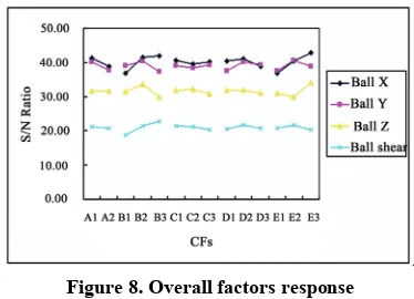
(5) From Figure8, it is observed that the variations of bond-ing time for the quality targets are small. Thus, the bonding time is considered as an adjustable factor and selected as C1. From the S/N ratio obtained in Figure 8, the final optimal combinations are inferred by four sets of parameters in sequence as [A1 B2 C1 D2 E2], [A1 B3 C1 D2 E2], [A1 B2 C1 D2 E3], [A1 B3 C1 D2 E3]. Al-Table 2. Control factors and levels for first bond process.
Factor Variables Description Level 1 Level 2 Level 3
1 A: Capillary Searching Speed (mil/ms) 0.1 0.14 —
[image:10.595.306.542.249.354.2]2 B: Bonding USG (mA) 80 90 100 3 C: Bond Time (ms) 8 14 20 4 D: Bond Force (grams) 15 25 35 5 E: Pre-Bleed USG (%) 25 45 65
[image:10.595.54.290.430.501.2]Figure 8. Overall factors response
Table 4. Comparisons of S/N ratio for four sets of optimal combination
S/N Ratio
Optimal Set Ball X Ball Y Ball Z Ball Shear Prediction 44.53 44.47 32.41 23.83 Set 1
Experiment 42.74 45.12 38.33 30.48 Prediction 45.11 41.29 28.65 25.01 Set 2
Experiment 41.4 43.15 32.33 29.84 Prediction 46.92 42.74 36.67 22.42 Set 3
Experiment 44.25 42.03 32.02 28.31 Prediction 47.5 39.56 32.91 23.6 Set 4
Experiment 46.77 43.47 31.53 30.1
though there are four sets of optimal parameters in solu-tion, a set of optimal parameters will be selected by con- firmation experiments. The confirmation test is under-taken by the fabrication of ten devices under four sets of optimal combinations respectively. Four sets of confir- mation for the experimental and predicted S/N are ob-tained as given in Table 4. In Table 4, the experimental result is calculated from the mean S/N ratio of testing results and the prediction of S/N ratio is obtained by util-izing a linear additive predictive model. The confirma-tion test reveals that the quality targets are satisfied by all the four sets of optimal combination. By comparing the
[image:10.595.112.486.532.722.2]Study of Green Behavior with a Focus on Mexican Individuals 39
closeness of S/N ratio of each set of prediction and ex-perimental result in Table 4, it is realized that the inter-actions of CFs are insensitive for Ball X and Ball Y, but the interactions for Ball Z and Ball Shear are sensitive.
With the interactions in laboratory tests, the optimal result obtained cannot be directly applied for customer service. In order to achieve optimal bonding performance and robustness in field operation, further experimental designs and tests are required [13]. For the present results obtained in laboratory, the results of ball size are accept-able by the quality target. The experimental S/N ratio of Ball Shear for Set 1 is higher than the other three sets of experimental results. With the higher S/N ratio in Set 1, the wire bonding process will be more robust. From the experimental confirmation tests, the final optimal pa-rameters for K&S Maxμm Plus are [A1 B2 C1 D2 E2], i.e. Capillary Searching Speed: 0.1 mil/ms, Bonding USG: 90 mAmp, Bonding Time: 8 ms, Bonding Force: 25 grams, and Pre-bleed USG: 45 %.
5. Conclusions
A systematic framework which consists of a system of equipment failure analysis, methods, process, and activi-ties, and a procedure is proposed for the maintenance and service of semiconductor equipment. The maintenance procedure in sequence starting from Maintenance Needs, Value Analysis, FMEA, Troubleshooting, Manufacturing Process Validation, and Optimal Setting to Operation is developed. By employing axiomatic design mapping integrated with Value Engineering, Quality Function De- ployment, Mechatronics Engineering, Techniques from R&D and Supplier, and Taguchi Method, the framework is highly effective in translating Maintenance Needs into Design Parameters for troubleshooting, and into Control Factors for process optimization. In the troubleshooting and process optimization of a wire bonder, the frame-work is applied to assure robust production quality in the first bond process by K&S Maxμm Plus. The systematic framework provides an effective and efficient scheme to provide maintenance and service for the acceptance or worth by customers.
Appendix
The lower levels of FRs and DPs are listed as follows. 1) Console System
FR1-1-1: Mechanism motion control FR1-1-2: Signal transmission FR1-1-3: Image processing
FR1-1-4: Communication relationship DP1-1-1: Electronic mechanism control DP1-1-2: Sensor interfaces
DP1-1-3: Image processing system DP1-1-4: Circuit connection and cabling FR1-2-1: Provide power for all components FR1-2-2: Circuit and mechanism protection
DP1-2-1: Power supply assembly
DP1-2-2: Electronic fuse and emergency stop
FR1-3-1: Motion movement, including function and message selections in the GUI
FR1-3-2: Command typing and entry of data DP1-3-1: Mouse device
DP1-3-2: Keyboard
FR1-4-1: Bonder software and applications FR1-4-2: Portable bond programs and applications DP1-4-1: Hard disk
DP1-4-2: Mobile storage device (Floppy, USB storage device, CD ROM, etc.)
FR1-5-1: Mechanism protection FR1-5-2: Fabrication process demand FR1-5-3: Auxiliary machinery DP1-5-1: Cooling air
DP1-5-2: Vacuum system and compressed air DP1-5-3: Air pressure with mechanisms
FR1-6-1: Precise wire feed for bonding continuously FR1-6-1-1: Control wire feed motion and timing FR1-6-1-2: Feed wire automatically
FR1-6-2: Optimal bonding quality FR1-6-2-1: Maintain the bond ball quality FR1-6-2-2: Looping performance
DP1-6-1: Feeding mechanism
DP1-6-1-1: Motorized spool assembly with sensor de-tection
DP1-6-1-2: Air guide and wire detect sensor
DP1-6-2: Optimal wire feed path in pneumatic system DP1-6-2-1: Tension the wire and hold the ball in the center of capillary
DP1-6-2-2: Optimizing air guide to reduce wire whip-ping
2) Bond Head Assembly
FR2-1-1: Required wire bonding quality by EFO FR2-1-1-1: Fine Pitch bonding
FR2-1-1-2: High yield and bond ability DP2-1-1: Three-phase controller of EFO.
DP2-1-1-1: Control of discharge energy of the EFO DP2-1-1-2: Control the wear and lifetime of electrode FR2-2-1: Proven reliability in operation
FR2-2-1-1: Eliminate motion wear FR2-2-1-2: High operational times FR2-2-2: Clamp performance
FR2-2-2-1: Active damping of clamping mechanical resonance
FR2-2-2-2: Shorter opening and closing time DP2-2-1: Wire contact in handling and mounting DP2-2-1-1: Compliant motion mechanism DP2-2-1-2: Fixed arm and bimorph arm
DP2-2-2: Wire clamp driver with voltage profiling for open-loop control
DP2-2-2-1: Bimorph clamp actuator DP2-2-2-2: Piezoelectric actuation
A Systematic Framework of Equipment Maintenance and Service with Application to Wire Bonder
40
FR2-3-1-1: Ball roundness
FR2-3-1-2: Fine pitch wire bonding capabilities FR2-3-1-3: High speed wire bonding
FR2-3-1-4: Minimize the loss of ultrasonic energy FR2-3-2: Good placement accuracy
FR2-3-2-1: Higher bonding accuracy
FR2-3-2-2: Good stability and reproducibility of cap-illary tip motion
FR2-3-3: Good bonding capability
FR2-3-3-1: USG applied before capillary contact sub-strate
FR2-3-3-2: USG applied during contact and bonding operation
DP2-3-1: Generation, transmission and focusing me- chanism of ultrasonic energy
DP2-3-1-1: Accurate ultrasonic amplitude and fre-quency
DP2-3-1-2: High frequency vibration of PZT
DP2-3-1-3: Increase system stiffness by using titanium DP2-3-1-4: Holder and horn mechanism
DP2-3-2: Vibration of transducer tip
DP2-3-2-1: Transducer material and structure DP2-3-2-2: Capillary clamping system of the trans-ducer
DP2-3-3: Ultrasonic energy by USG in bonding proc-ess
DP2-3-3-1: Capillary tube and ultrasonic profile DP2-3-3-2: Bonding ultrasonic control circuitry FR2-4-1: Precise motion and force control on bond head
FR2-4-1-1: Capable of high acceleration FR2-4-1-2: High motion repeatability FR2-4-1-3: Bonding accuracy
FR2-4-2: Monitor Z-axis position for force control FR2-4-2-1: Monitor bonding tool position precisely FR2-4-2-2: Real-time signals response
FR2-4-3: Speed control of bond head FR2-4-3-1: Higher acceleration
FR2-4-3-2: High performance of control system FR2-4-4: Capillary and wire motion control
FR2-4-4-1: Detecting and switching the approaching to substrate
FR2-4-4-2: Searching speed requirement DP2-4-1: Voice coil actuating control system
DP2-4-1-1: Minimize the mass of the motor and bal-ance the centre of gravity of the rotational inertia.
DP2-4-1-2: Electromagnetic and mechanical subsys-tems
DP2-4-1-3: Accurate servo mechanism DP2-4-2: Encoder assembly
DP2-4-2-1: High resolution optical grid DP2-4-2-2: Electronic encoder system DP2-4-3: Speed control system DP2-4-3-1: Low inertia mechanism DP2-4-3-2: High bandwidth in control loop
DP2-4-4: Capillary and wire motion control system DP2-4-4-1: Detection and switching control mecha-nism
DP2-4-4-2: Searching speed control circuitry FR2-5-1: Capable of detection
FR2-5-1-1: Enhance detection signal FR2-5-1-2: Avoid false detection
FR2-5-2: Test for the outcome of the bonding process FR2-5-2-1: Detect non-stick on pad
FR2-5-2-2: Detect non-stick on lead
FR2-5-2-3: Detect the tail left on the capillary after wire-cycle bonding
FR2-5-2-4: Detect ball formation by electronic firing DP2-5-1: Effective detector
DP2-5-1-1: High-impedance devices DP2-5-1-2: Noise eliminator
DP2-5-2: Electrically detectable interface system DP2-5-2-1: Current from bond pad to machine chassis ground
DP2-5-2-2: Current from lead to machine chassis ground
DP2-5-2-3: Current from wire tail to machine chassis ground
DP2-5-2-4: Current from wire tail to wand
FR2-6-1: Support precision machine components with rotational motion
FR2-6-1-1: Robust bearing
FR2-6-1-2: Infinite lifetime/service time FR2-6-2: Provide motion accuracy of bond head FR2-6-2-1: Minimize the restoring force
FR2-6-2-2: Increase bonding speed and line pitches DP2-6-1: Robust linkage with flexure pivot
DP2-6-1-1: Stainless steel cross-flexure pivot bearings DP2-6-1-2: Zero wear and friction operation
DP2-6-2: Bond head inertia and stiffness in assembly DP2-6-2-1: Flexure bearing pivots in loading angle DP2-6-2-2: High stiffness in assembly
3) Vision system
FR3-1-1: Sufficient illumination FR3-1-2: Clear image features
FR3-2-1: High accuracy and robustness FR3-2-2: Faster image processing
FR3-3-1: Show bond height difference and capture wider image of bonds
FR3-3-2: Image features requirements
DP3-1-1: Illumination assembly and work light DP3-1-2: Image acquisition system
DP3-2-1: Pattern matching by image processing tools DP3-2-2: High-speed processor
DP3-3-1: Mechanism for different magnifications DP3-3-2: Installation and calibration
4) Material Handling System
FR4-1-1: Pull the materials from input magazine into work holder
A Systematic Framework of Equipment Maintenance and Service with Application to Wire Bonder 41
FR4-1-3: Index the materials into bond site and index motion
FR4-1-4: Eject the materials into output magazine FR4-2-1: Mechanism secures the carrier during bond-ing operation
FR4-2-2: Hold the fine-pitch and specific materials bonding more stable
FR4-3-1: Raise temperature before entering the bond site FR4-3-2: Maintain the bonding temperature
FR4-3-3: Prevent damage to devices after bonding by rapid heating and cooling
FR4-4: Prevent materials damaged during transportation FR4-4-1: Prevent devices damaged during transporta-tion from input magazine or into output magazine
FR4-4-2: Prevent devices damaged during injection FR4-4-3: Prevent devices damaged during ejection FR4-5-1: Inject/eject the magazine
FR4-5-2: Jog/reverse magazine DP4-1-1: Injector assembly
DP4-1-2: Front and real rails assembly DP4-1-3: Indexer assembly
DP4-1-4: Ejector assembly DP4-2-1: Clamp mechanism DP4-2-2: Hold down mechanism DP4-3-1: Pre-heat plate
DP4-3-2: Bond-site heat plate DP4-3-3: Post-heat plates
DP4-4-1: Wall sensors on both sides of input and output DP4-4-2: Inject Y-axis sensor detection
DP4-4-3: Jam detection sensor during ejection DP4-5-1: Gripper motor injects and ejects magazines DP4-5-2: Z-axis motor drives the jog/reverse motion 5) XY-Table Mechanism
FR5-1-2: Less structural vibration FR5-2-1: High motion precision FR5-2-2: High precision in fabrication DP5-1-1: High acceleration
DP5-1-2: High damping in material and servo loop DP5-2-1: Decrease joint clearance
DP5-2-2: Decrease the wear of motion joint
REFERENCES
[1] G. G. Harman, “Wire bonding in microelectronics, material, processes, reliability, and yield,” 2nd edition, McGraw Hill, New York, 1997.
[2] C. Boit, R. Weiland, A. Olbrich, U. Muehle, and B. Sim- mnacher, “Failure analysis concepts for microelectronics technologies and manufacturing of the future,” Proceedings of SPIE, Vol. 4406, pp. 1–12, 2001.
[3] D. T. Rooney, D. Nager, D. Geiger, and D. Shanguan, “Evaluation of wire bonding performance, process conditions, and metallurgical integrity of chip on board wire bonds,” Microelectronics Reliability, Vol. 45, No. 2, pp. 379–390, 2005.
[4] A. Garg and S. G. Deshmukh, “Maintenance management: Literature review and directions,” Journal of Quality Maintenance Engineerings, Vol. 12, No. 3, pp. 205–238, 2006.
[5] M. Murray, K. Fletcher, J. Kennedy, P. Kohler, J. Chambers, and T. Ledwidge, “Capability assurance: A generic model of maintenance,” ICOMS-96, Maintenance Engineerings Society of Australia Capability Assurance, paper 72, 1996.
[6] B. S. Blanchard, “System engineering management,” John Wiley & Sons, New York, 1991.
[7] M. Braglia, G. Fantoni, and M. Frosolini, “The house of reliability,” International Journal of Quality and Relia- bility Management, Vol. 24, No. 4, pp. 420–440, 2007. [8] D. A. Bradley, D. Dawson, N. C. Burd, and A. J. Loader,
“Mechatronics: Electronics in products and processes,” Chapman & Hall, London, 1993.
[9] N. P. Suh, “Axiomatic design: Advances and appli- cations,” Oxford Press, New York, 2001.
[10] B. S. El-Haik, “Axiomatic quality: Integrating axiomatic design with six-sigma, reliability, and quality Enginee ring,” John Wiley & Sons, New York, 2005.
[11] H. A. Mohsen and E. Cekecek, “Thoughts on the use of axiomatic designs within the product development process,” Proceedings of 1st International Conference of Axiomatic Design, Cambridge, Massachusetts, USA, 2000.
[12] G. Taguchi, “Taguchi methods: Signal-to-noise ratio for quality evaluation,” Michigan: American Suppliers Institute Press, Vol. 3, 1991.
[13] M. S. Phadke, “Quality engineering using robust design,” Prentice Hall, London, 1989.
[14] R. Whitcomb and M. Rioux, “Failure modes and effects analysis (FMEA) system deployment in a semiconductor manufacturing environment,” Proceedings IEEE/SEMI Advanced Semiconductor Manufacturing Conference Works, pp. 136–139, 1994.