dimensional rimming flow in a horizontal cylinder
J. Williams, S. Hibberd, H. Power, and D. S. Riley
Citation: Physics of Fluids (1994-present) 24, 053103 (2012); doi: 10.1063/1.4718653 View online: http://dx.doi.org/10.1063/1.4718653
On the effects of mass and momentum transfer from
droplets impacting on steady two-dimensional rimming
flow in a horizontal cylinder
J. Williams,1S. Hibberd,1H. Power,2and D. S. Riley1
1School of Mathematical Sciences, University of Nottingham, University Park,
Nottingham NG7 2RD, United Kingdom
2Department of Mechanical, Materials and Manufacturing, University of Nottingham,
University Park, Nottingham NG7 2RD, United Kingdom
(Received 8 June 2011; accepted 6 April 2012; published online 30 May 2012)
Motivated by applications in aero-engines, steady two-dimensional thin-film flow on the inside of a circular cylinder is studied when the film surface is subject to mass and momentum transfer from impacting droplets. Asymptotic analysis is used systematically to identify distinguished limits that incorporate these transfer effects at leading order and to provide a new mathematical model. Applying both analytical and numerical approaches to the model, a set of stable steady, two-dimensional solutions that fit within the rational framework is determined. A number of these solutions feature steep fronts and associated recirculating pools, which are undesirable in an aeroengine since oil may be stripped away from the steep fronts when there is a core flow external to the film, and recirculation may lead to oil degradation. The model, however, provides a means of investigating whether the formation of the steep fronts on the film surface and of internal recirculation pools can be delayed, or inhibited altogether, by designing jets to deliver prescribed distributions of oil droplets or by the judicious siting of oil sinks. Moreover, by studying pathlines, oil-residence times can be predicted and systems optimized.C2012 American Institute of Physics. [http://dx.doi.org/10.1063/1.4718653]
I. INTRODUCTION
This study concerns rimming flow in a thin liquid film lining the inside of a horizontal circular cylinder forming the outer part of a cylindrical annulus. Rimming flow models are relevant to applications as diverse as cream separation, Rushak and Scriven,1and the ceramic coating of pipes, Menekseet al.2The particular motivation for the current study is an application to high-speed gas turbines, where rimming flows feature in the processes of the cooling and lubrication of aero-engine bearing chambers. In this application the motion of thin oil films is affected or effected, depending on whether the substrate is moving or not, by the impact of oil droplets. The cylindrical walls of the chamber comprise two moving shafts – the HP (high pressure) and IP (intermediate pressure) shafts, which may co-rotate or contra-rotate – and stationary sections. The fluid in the body of the chamber is a mixture of air and oil, driven round by the rotation of the central IP shaft: oil enters the chamber from an injector, forms a mist in the core air, and eventually impacts as small droplets on the film lining the outer wall. The oil then flows around the film and leaves the chamber through sinks located on the outer cylindrical wall and collects in external sumps. The function of the oil is to act as a lubricant for the bearings, and also as a coolant of the hot metal surfaces. It is important that a constant flow of oil is maintained around the wall, since stagnant or dry patches may lead to overheating and, in extreme cases, to coking.
It is the behaviour of the oil film that forms on the inside of the outer shaft of an aero-engine bearing chamber that is the primary concern in this study, which aims to develop a self-consistent model of droplet impact in rimming flow, and hence to derive and analyze expressions for film thickness. Thus the problem posed is to investigate the flow of a thin film of oil on the inside of
a smooth rigid cylinder, which may be rotating or stationary, under the influences of gravity and a core flow consisting of a rotating mixture of air and oil droplets; thermal effects are not considered in the current study.
In an aero-engine, there will be a start-up phase where droplets impact on an initially dry surface and spread; as more droplets impact the surface will become coated with a continuous film and ultimately will reach a steady-state operating condition. The problem of the formation of films via droplet impact has received recent attention by Driscoll et al.3 In the “steady state,” droplets interact with the film in a complex manner, rebounding, splashing, and breaking up, as well as being absorbed, Farrall,4 Farrallet al.,5Farrallet al.6 Such impact problems are extremely challenging, but theoretical progress has been made in the case of an isolated droplet, see, for example, Hicks and Purvis7and references cited therein. Therefore, it is both reasonable and pragmatic to consider a continuous distribution obtained by averaging the droplet and air core flows spatially, rather than a discrete one. A similar approach was adopted previously in two limiting models of droplet impact at the surface of rimming film flow. In earlier investigations of draining and filling flows, Noakes,8 Noakeset al.9ignored momentum, and regarded mass as being added continuously at the film surface and removed continuously at a sink. In contrast, Villegas-D´ıaz,10 Villegas-D´ıazet al.,11 Villegas-D´ıazet al.12 model the two-phase core flow as a fluid of low density which imparts momentum to the film via a constant surface shear along the film interface and droplet mass transfer is neglected.
Anad hocmodelling approach would simply be to combine the independent contributions of mass
and momentum. This approach, however, is not adopted, instead continuity of mass and momentum is sought across the interface between the film and a prescribed core flow. The equation governing the film height h is determined by identifying distinguished asymptotic limits and the resulting equations’ relationship to previous models established.
It is well established that a complex variety of fluid-dynamical behaviour arises in rimming flow, see, for example, Thoroddsen and Mahadevan.13There is correspondingly an ever-growing literature on the mathematical analysis of this problem: in particular, Moffatt,14Pukhnachev,15Johnson16and O’Brien and Gath17focus on a simple lubrication model; Ashmoreet al.,18Hosoi and Mahadevan,19 Noakes,8Tirumkudulu and Acrivos,20Wilsonet al.,21and Acrivos and Jin22consider various higher order theories; some in addition investigate surface-tension effects. More recent studies, Benilov and O’Brien,23Noakeset al.,24and Kelmanson25have focussed on inertial effects, while others, Hinch and Kelmanson,26Hinchet al.,27and Noakeset al.28have used intricate multiple-timescale analysis to describe the evolution of instabilities in rimming flow. (Some of the papers cited here in turn cite many more papers, many of which are concerned with coating flow, the flow on the exterior of a cylinder. For our purposes this brief list of references is sufficient.)
In the simplest model of rimming flow a balance between viscosity and gravity is assumed and the effects of inertia and surface tension are neglected. Applying the ideas of lubrication theory to this situation, Moffatt14studied the maximum load of liquid that can be supported on the outside of a cylinder (his analysis applies to both coating and rimming flows with appropriate modifications in interpretation). The problem of rimming flow was revisited by Johnson16and by Benjamin, Pritchard and Tavener in unpublished work, with both studies addressing the question of the existence of weak solutions containing shocks (where the free-surface height changes rapidly in a very narrow region of the domain). It was Johnson16 who first recognized the relevance of discontinuous solutions of the equation determining the steady-state film profile as a function of the azimuthal angle. Benjaminet al.made a deeper study and,inter alia, considered the stability of the solutions that Johnson16 had identified and the influence of surface tension, the latter effect being investigated in more detail by Ashmore et al.18 A more recent, comprehensive study of the effects of surface tension and higher order gravitational effects has been undertaken by Villegas-D´ıaz et al.12 in a study of rimming flow subject to constant surface shear with the aim of resolving issues regarding existence, uniqueness, and stability of such weak solutions. (For a review of experimental work, see Evanset al.29)
There is a long-standing issue of correctly embedding shock structures in thin films within rational asymptotic schemes. Some progress has been made, see, for example, Noakes,8 Benilov
problem. In brief, while promising progress is being made on developing sophisticated packages to compute flow in aero-engine bearing chambers (see Luet al.,32for example), the authors know of no code that has satisfactorily resolved the interface between the liquid film and core two-phase flow and details of the film flow itself. Thus detailed analysis, such as that presented in this study, is currently the best means of gaining physical insight into this complex flow.
The structure of the paper is as follows. In Sec. II(and AppendixA), the governing system of equations is described. In Sec.III(and AppendixB), a systematic asymptotic analysis of the equations is developed and the key generic film evolution equation,(21), together with its relationship to previous studies, TableII, presented. In Sec.IV, the primary validation of the numerical code is undertaken. This numerical code together with theoretical analysis is applied in Sec.Vto the case of a film on a stationary cylinder with significant droplet momentum but negligible mass transfer at the film surface, while in Sec.VInumerical solutions and their stability when droplet momentum is dominant are discussed. In Sec.VII, the case of significant mass and momentum transfer and the effects of varying mass flux, the film mass and sink position are considered. Finally in Sec.VIII, conclusions are summarized.
II. MODEL FORMULATION
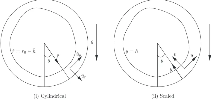
In the idealized model, the outer shaft of the aero-engine bearing chamber is represented as a cylinder of radius r0 with a thin film of liquid on its inner surface. Define cylindrical polar coordinates ˆr, with origin at the centre of the horizontal cylinder, andθ, measured anti-clockwise from the downward vertical, see Figure1(a). The cylinder wall is described by ˆr=r0, and the film surface by ˆr=r0−hˆ(θ,tˆ) where ˆh ≥0.
The effects of liquid droplets on the film are modelled as contributions to the surface forces and to the mass flux across the film surface. The droplets are assumed to be of the same constant densityρ and viscosityμ as the liquid film. The flow is assumed two-dimensional and the fluid incompressible and Newtonian.
In this study, we are not concerned with the detail of the two-phase core flow, so the behaviour “far” (on the scale of the film thickness) from the cylinder wall is not included in the model. For simplicity, the two-phase core fluid is modelled as an inviscid mixture (in an average sense) and the flow is assumed to have a constant local pressure ˆpE outside the film and an average droplet velocity near the film surfaceˆuEat a constant angle relative to the cylinder wall and at a constant speed such
that the film may be driven against gravity; no rebounding, splashing, or breaking up of droplets is considered. Consistent with the core-flow averaging, mass, and momentum transfer are considered across a smoothed film surface. SubscriptsEandIare used to refer to the two-phase gas-droplet mix
θ ˆr ˆ
r=r0−ˆh
ˆ ur ˆ uθ
g
θ y
y=h v
u
[image:4.612.128.484.546.713.2](i) Cylindrical (ii) Scaled
external to the film and the liquid in the film, respectively; when there is no ambiguity, the subscripts will be dropped in what follows.
In the film, the fluid has kinematic viscosityν=μ/ρand the flow is subject to a gravitational fieldg= −gj, wherejis a unit vector pointing vertically upwards andgis the acceleration due to gravity, thus the velocity,ˆuI=( ˆuI r,uˆIθ), and pressure, ˆpI, satisfy the continuity and Navier–Stokes equations
∇ ·ˆuI=0, (1)
∂ˆuI
∂t +ˆuI· ∇ˆuI= −ρ
−1∇pˆ
I +ν∇2ˆuI+g; (2)
2π-periodic solutions will be sought to(1)and(2).
The core two-phase flow comprises air with density ρg and a volume fraction α of liquid droplets with densityρ(andρI ≡ρ).ρE =αρ +(1−α)ρgis the average density of the mixture; given that (1−α)ρgαρ, the two-phase fluid is modelled as continuous and of constant density ρE=αρ.
Droplets impacting on the film surface, which is modelled as a single interfaceS(t), described byχ(x,t)=0, transfer mass as well as momentum into the film. This interface is a surface at which density and velocity are discontinuous (see AppendixAfor further details).
The velocity of the interface ˆUjfollows from conservation of mass (cf. Sec. 1 in AppendixA):
ρ(α−1) ˆUjnj =ρ(αuˆE j−uˆI j)nj. (3)
The normal and tangential components of the stress boundary conditions on the interface are obtained from the conservation of momentum (see Sec. 2 in AppendixA) as
−σκ= αρ
1−α[ ˆui][ ˆuj]njni−[ ˆTi j]njni, (4)
0= αρ
1−α[ ˆui][ ˆuj]njti−[ ˆTi j]njti; (5) [.] denotes the jump of quantities across the boundary between the two-phase flow and the film, so, for example, [u]=uE−uI;σ is an effective surface tension coefficient,tiis the unit tangent vector at the interface such thatniti=0, and ˆTi j are the fluids’ stress tensors.
In the current case, the film surface is χ≡ −rˆ+r0−hˆ(θ,tˆ)=0. Correspondingly,
n=(nr,nθ), the unit normal pointing towards the centre of the cylinder has components
nr = −N, nθ= −
N
ˆ
r
∂hˆ
∂θ, (6)
where
N =
⎛ ⎝1+
1 ˆ
r
∂hˆ ∂θ
2⎞
⎠
−1/2
, (7)
and the surface curvature is given byκ = ∇ ·n|rˆ=r0−hˆ, i.e.,
κ= ∇ ·n= −N
3
ˆ
r
⎛ ⎝1+ 2
ˆ
r2
∂hˆ ∂θ
2
+1
ˆ
r
∂2hˆ
∂θ2
⎞
⎠. (8)
The final expressions of the stress matching conditions (A19)and(A20) are given in Sec. 2 in AppendixA.
The interface positionχ=0 is a material surface, hence ∂χ
∂t +Uˆj
∂χ ∂xj
which, using(3), yields the kinematic condition
(1−α)∂hˆ ∂tˆ +
ˆ
uIθ 1 ˆ
r
∂hˆ ∂θ −uˆI r
=α
ˆ
uEθ 1 ˆ
r
∂hˆ ∂θ −uˆEr
, on rˆ=r0−hˆ. (10)
Finally, mass leaves a bearing chamber through one or more outlets, which are modelled as sinks distributed on the chamber wall. The sinks are described mathematically by specifying the normal velocity at the wall
ˆ
uI r =vˆcyl. (11)
Here, ˆvcyl is uniform across the sinks such that at steady state the total influx at the film surface is balanced by the total outflux at the sinks, while ˆvcyl =0 elsewhere on the cylinder. For simplicity, the azimuthal velocity is taken to match the motion of the cylinder wall everywhere around the boundary (i.e., sinks are ignored), so that ˆuIθ =uˆcyl where ˆucyl =r0 for a cylinder rotating anticlockwise with angular velocity; for a film driven purely by the impacting droplets’ momentum, the cylinder is stationary=0.
III. MODEL DERIVATION
The study concentrates on thin film flows for which a typical film thickness such that ˆh0r0 can conveniently be defined by
ˆ
h0= 1 2π
2π
0 ˆ
h(θ,0)dθ. (12)
It is natural to employ a local coordinate system using a non-dimensional radial coordinate,y
measuring distance inwards from the cylinder’s surface, see Figure1(ii). The scalings for the film variables are quite standard in rimming-flow analysis (Uis a characteristic film speed); the scalings of the impact velocity have been chosen to ensure a balance between the radial flux of azimuthal droplet momentum∼uˆEθ(αρuˆEr) and the surface viscous shear∼μ∂uˆIθ/∂rˆ,
ˆ
t=r0t/U, rˆ=r0(1−y), hˆ =hˆ0h, α=ka, =hˆ0/r0,
( ˆpI,pˆE)=ρU2−1(p,pE −−1Wef−1), ( ˆuI r,uˆIθ)=U(−v,u),
( ˆuEr,uˆEθ)=U−(k+β)/2(−βvE,uE), ( ˆvcyl,uˆcyl)=U(vcyl,ucyl); (13)
Wef =U2ρr03/σhˆ20, Ref =Uhˆ0/ν, Fr=U2/ghˆ0,
where it is assumed thata=O(1), Ref=O(1), Wef=O(1), and Fr=O(1) as→0. The timescale for motion in the film is that of a particle of fluid moving around the cylinder.
Note thatkcontrols the strength ofα, the volume fraction of droplets in the two-phase flow; βcontrols the impact angle of the droplets since ˆuEr/uˆEθ =O(β); the pressure in the two-phase flow is measured relative to (Wef)−1 for later convenience; Wef, Ref, Fr, and denote reduced Weber number, reduced Reynolds number, Froude number, and aspect ratio, respectively. It should be emphasized that Wef may in practice be quite large, but surface tension provides an important smoothing mechanism and is thus retained in the analysis, cf. Benilovet al.33
The dimensional film area is
ˆ
A=
π
−π r0
r0−hˆ ˆ
rdˆrdθ=hˆ0r0
π
−πh+ h2
2 dθ, (14)
which naturally leads to a leading-order non-dimensional measure
A=
π
−πhdθ. (15)
A. Distinguished limits: The effect of droplet impact
The details of the derivation of the asymptotic form of the film-evolution equation are relegated to AppendixB. To leading order, the dimensionless profilehis
∂h0
∂t −
∂
∂θ Ref ∂N0
∂θ +Fr−1sinθ
h3 0 3
+ ∂
∂θ T0 h2
0 2
+ ∂
∂θ
ucylh0
−vcyl−M0=0,
(16)
where the effects of droplet impact are embedded inN0,T0, andM0, the leading-order terms in the small-expansions ofN,T, andM. Analysis of(B7)–(B9)reveals that contributions arise from these terms atO(1) as→0 provided that
|β| ≤1 k≥2−β (17)
in which case
N ∼ −Wef−1 h0+
∂2h 0
∂θ2
+a1+βv2E +. . . , (18)
T ∼ −Refa uEvE−1−βu2E ∂h0
∂θ +1+βv2E ∂h0
∂θ − k+β
2 uvE
+k−β+2
2 2uuE∂h0 ∂θ −vuE
+. . .
, (19)
M∼a k∂h0
∂t +
k−β
2 uE∂h0 ∂θ −
k+β−2
2 vE +. . .
. (20)
Note that the first three terms on the right-hand side of (19) arise from the flux across the surface of the droplets’ momentum in the direction tangential to that surface, namely,
a(vE−uE∂h/∂θ)(vE∂h/∂θ+uE). The exact form of the evolution equation(16)depends on the droplet fraction in the core flow (k) and droplets’ inclination angle (β). In view of (17), it follows thatk≥1 and hence the model is restricted to dilute droplet volume fractions (consistent with the assumption that the two-phase flow may be treated as inviscid).
Droplets approach the film at a prescribed angleφto the local tangent to the cylindrical wall, where tanφ=βvE/uE. Physically, as illustrated in Figure2,β =1, 0,−1 correspond to impacts at shallow, moderate, and steep angles, respectively.
u
Ev
Eβ
= 1
[image:7.612.218.392.519.713.2]β
= 0
β
=
−
1
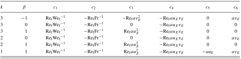
TABLE I. Coefficients appearing in(21)for typical admissible values ofβandk.
k β c1 c2 c3 c4 c5 c6
3 −1 RefWef−1 −RefFr−1 −Refav2E −RefauEvE 0 avE
3 0 RefWef−1 −RefFr−1 0 −RefauEvE 0 0
3 1 RefWef−1 −RefFr−1 Refau2E −RefauEvE 0 0
2 0 RefWef−1 −RefFr−1 0 −RefauEvE 0 avE
2 1 RefWef−1 −RefFr−1 Refau2E −RefauEvE 0 0
1 1 RefWef−1 −RefFr−1 Refau2E −RefauEvE −auE avE
Substituting(18)–(20)into(16), and omitting straightforward details, it is possible to write the generic film evolution equation corresponding to all possible cases that can exist on the parameter space defined in(17)as
∂h
∂t +
∂ ∂θ
⎛ ⎜ ⎜ ⎜ ⎝
Surface Tension
c1
∂h
∂θ + ∂3h
∂θ3
h3 3 +
Gravity
c2sinθ h3
3 +
Droplet Momentum
c3(θ)
∂h
∂θ +c4(θ)
h2 2
⎞ ⎟ ⎟ ⎟ ⎠
+ c5(θ)
∂h
∂θ +c6(θ)
Droplet Mass
+∂θ∂ ucylh
Wall Rotation
−vcyl
Sink
=0. (21)
The coefficients appearing in(21)are given in TableIfor a selection of admissible values ofβ and
ksatisfying(17); note thatβandkneed not be integer, but that the selected integer values illustrate the full range of interesting qualitative behaviours. At a shallow inclination (β=1), momentum is dominant for lower droplet fraction (k=3), asc5 andc6 are negligible, while for higher droplet fraction (k=1) both momentum and mass transfer are significant, and so on.
In Eq.(21), the term proportional toc5 corresponds to the azimuthal component of the mass flux andc6to the radial component. In contrast, the whole term involvingc3andc4is a contribution from droplet momentum, but the individual terms proportional toc3andc4do not lend themselves to a simple physical interpretation.
The nature of the constant-shear model of Villegas-D´ıazet al.12(hereafter referenced simply as VPR) in the context of the current generalized model is clear from(17)–(20): it is for|β|<1 and
k>2−βthat droplets impart momentum equivalent to the effect of a constant surface shear force (i.e., thec4term alone). If|β| =1 andk>2−β, thec3term in the droplet momentum is significant but is absent in the model of VPR. Finally, we note that if−1≤β <1 andk=2−β, a constant mass flux term (i.e., thec6term) of the form modelled in Noakeset al.9features, but, in contrast to Noakes’s model,8momentum is not negligible. TableIIsummarizes the terms that arise in previous studies that lead to an equation of similar form to(21).
In Secs.IV–VI, we consider cases where the flow field is driven solely by the transfer of droplet momentum, with a stationary cylinder wall, i.e.,ucyl=0, and the mass flux into the film is negligibly small (c5=c6=0). This implies that|β| =1 andk>2−β; specifically we considerβ =1 andk
=2 and 3. Later in Sec.VII, we study the case of significant droplet momentum transfer and mass flux at the film surface, i.e.,|β| ≤1 andk=2−β, in order to complete the exploration of the whole of the parameter space defined in(17).
IV. FILM PROFILE ON A STATIONARY CYLINDER WITH SIGNIFICANT DROPLET MOMENTUM BUT NEGLIGIBLE MASS TRANSFER AT THE FILM SURFACE
To simplify the governing equation in the case of negligible mass transfer ∂h
∂t +Ref
∂
∂θ Wef−1 ∂ h
∂θ + ∂3h
∂θ3
h3 3 +Fr
−1sinθh3
3 +auE uE ∂h
∂θ −vE
h2 2
TABLE II. Coefficients appearing in ∂∂ht +∂θ∂ c1
∂h
∂θ+∂
3h
∂θ3
h3
3 +c2sinθh 3 3 +
c3∂∂θh+c4h 2 2
+c5∂∂θh+c6
+ ∂
∂θucylh−vcyl=0 and the corresponding coefficients featured in other studies;×not consideredconsidered.
Higher order
c1 c2 c3 c4 c5/ucyl c6/vcyl terms
Leading-order cubic × × ×
Momentum only (see Sec.IV) ζ −1 αu 1 0 0
Mass and momentum RefWef−1 −RefFr−1 Refau2E RefauE−vE −auE avE
Noakeset al.(Ref.9) (rotation and mass) −1 0 0 1 λI
Villegas-D´ıaz (Ref.10) (rotation and shear) B−1 − 0 γ 1 0
Moffatt (Ref.14) × × × ×
Black (Ref.34) Smoothing by
surface tension × × × ×
Black (Ref.34) Smoothing by gravity × × × ×
Black (Ref.34) Rotating × × × ×
Benjaminet al.(unpublished) × ×
Acrivos and Jin (Ref.22),
Tirumkudulu and Acrivos (Ref.20) × × ×
Hinch and Kelmanson (Ref.26),
Hinchet al.(Ref.27) × × × ×
in cases in parameter space where|β| =1 andk>2−β, i.e., dominant droplet momentum withc5
=c6=0, we define the characteristic film thickness as ˆh0=(Uν/g)
1
2 so that RefFr−1=1, and the characteristic velocity asU =(νg/a2u2
Ev2E)1/3. The final term in(22)which represents azimuthal momentum becomes
RefauE uE∂
h
∂θ −vE
=RefauE|vE|
uE
|vE| ∂h
∂θ +1
=sgn(uE) αu∂
h
∂θ +1
(23)
with sgn(uE) = uE/|uE| and αu =uE/|vE|; note that vE is always negative. On introducing ζ =RefWef−1=σ3/μU,(22)becomes
∂h
∂t +
∂q
∂θ =0, q =ζ
h3
3 ∂h
∂θ + ∂3h
∂θ3
−sinθh
3
3 +sgn(uE) αu ∂h
∂θ +1
h2
2 . (24)
To summarize, on choosing ˆh0andUas above, the parameter values in(21)arec1≡ζ,c2≡ −1, c3≡αu, andc4≡1.
Steady-state solutions are first sought for a dominant balance between surface shear and gravity (ζ,αu=0) as the problem is purely algebraic and an explicit solution exists. The solutions for small non-zeroζ,αuare expected to be close to these, except where derivatives ofhare large, causing the terms involvingζ,αuto have a leading-order effect.
For definiteness, we take the azimuthal velocity to be positive, i.e., sgn(uE)= +1, and so
q = −sinθh 3
3 +
h2
2 . (25)
Black34was the first to present in-depth analysis of this particular flow. When 0<q<1/6, there is a single, bounded, neutrally stable film profile which is smooth and completely wets the cylinder’s surface. This profile has vertical symmetry, its thickness being a maximum atθ=π/2, i.e., at the equator on the “rising side” of the flow, and a minimum at the point diagonally opposite. There are two other profiles: a C∞-profile which is totally negative and physically infeasible, and an unbounded profile consisting of two disconnected positive and negative branches. When A=Ac
by introducing a shock on the side of the cylinder where the fluid flows upwards (i.e., by jumping between the two branches).
To leading order, withq=1/6 and a shock atθ=θK, we have
A= 3
2ln
2 cos (θK/3−π/6)+
√
3 2 cos (θK/3−π/6)−
√
3
; (26)
whenθK→0,A→ ∞according to
A= 3
2ln
6√3 θK
+ θK
√
3+O(θ 2
K). (27)
As highlighted by Black,34the result thatA→ ∞as the shock position approaches the lowest point of the cylinder (θ =0) contrasts with that for the problem of flow around a rotating cylinder with zero surface stress whenAasymptotes to a finite value.
Whenq>1/6, there is no completely wetting solution, but so-called curtain solutions which become unbounded at the north and south poles of the cylinder may exist – these solutions are outside the scope of the present study. (Such solutions are briefly discussed in Black,34 who also gives explicit expressions for the real solutions of the cubic equation.)
In the case of negative azimuthal velocity, sgn(uE)= −1, the governing equation is
q = −sinθh 3
3 −
h2
2 , (28)
solutions to which are obtained by taking the mirror image of the solutions (i.e.,θ → −θ) to(25)
withq<0. Without loss of generality, the analysis hereafter is restricted touE>0.
A. Shock solutions
Of key physical interest is the study of bounded, completely-wetting, steady-state film profiles. There are many such profiles, including, in principle, infinitely many featuring multiple shocks. If shocks are present, then forq<1/6 there must be an even number of them. Forq=1/6 there must be an odd number. Whether such profiles are physically realisable, however, will depend on their stability.
In a physical system, surface tension and the droplet momentum locally smooth the shock profiles. Even when 0< ζ,αu 1, the termsαu∂h/∂θ andζ ∂3h/∂θ3in(24)can be significant in the region of a shock and can determine whether such shock solutions are feasible in the context of a mathematically rational asymptotic structure. By looking at inner steady-state solutions of(24)in a region around a shock atθ=θK, and considering the possibility of matching them asymptotically with the outer solutions defined by the cubic polynomial(25), which in 0< θ < πhas two positive real rootsh=hjsay, wherej=1, 2 on the upper and lower branches, respectively, and a negative rooth3, it is possible to analyze which shock structures are feasible (for more details about this type of analysis see Black,34Villegas-D´ıazet al.12and Benilovet al.33).
Omitting all the detail, the results on smoothing can be summarized as follows. WhenAexceeds
Ac=3.9509, then for
r αu=O(ζ1/3) asζ →0 (surface tension and droplet momentum both significant): smoothed backward- (forward-) facing shocks located in 0< θ < πare feasible – the inner solution has an oscillatory (monotonic) match with the outer. This also holds if surface tension is dominant (i.e.,α3u ζ 1 asζ →0);
r ζ α3
u1 as αu → 0 (droplet momentum dominant): a smoothed forward-facing shock located inπ/2< θ < πis feasible – the inner solution has a monotonic match with the outer.
−2 0 2 0
1 2 3
(a)
h
θ 0 −2 0 2
1 2 3
(b)
h
θ 0−1 0 1 2 3
1 2 3
(c)
h
θ
−1 0 1 2 3
0 1 2 3
(d)
h
θ 0−1 0 1 2 3
1 2 3
(e)
h
θ 0−1 0 1 2 3
1 2 3
(f)
h
θ
FIG. 3. Profiles ofhagainstθillustrating various possible shock combinations when surface tension and droplet momentum are both insignificant. (a) stable; (b)–(d) unstable; (e) and (f) stable according to kinematic wave theory, but not seen in numerical solutions (see later). The arrows indicate the direction of travel of infinitesimal perturbations.
By looking at the evolution of an infinitesimally small perturbation ξ(θ,t) to a steady state solutionhsof (24), cf.(32)withζ,αu=0, as suggested by Moffatt14and by Benjaminet al.(see also Villegas-D´ıaz et al.12 and Benilovet al.33), it is possible to show that three of the solutions reported in Figure3are unstable. The motion of a small perturbation is described by the kinematic wave equation with wave velocitywgiven by
w=(dq/dh)h=hs(θ)= −h
2
ssinθ+hs =h3scosθ/3(dhs/dθ), (29)
provided the derivative is non-zero in the final identity. Noww <0 on the upper solution branch of cubic equation(25)andw >0 on the lower, hence disturbances travel towards a backward-facing shock and away from a forward-facing shock.
Significant progress can be made directly by noting that waves are unable to travel through a point where w=0 and, if waves travel towards that point, energy is focussed and the amplitude of the disturbance grows unboundedly. Thus, in terms of linear theory, such unbounded growth might lead to interface rupture or blow up and the interface is unstable. Furthermore, if waves travel towards a shock, then that shock can adjust slightly and absorb the disturbance, leaving a stable structure.
[image:11.612.127.484.83.342.2]V. NUMERICAL SOLUTIONS FOR CASES OF DOMINANT DROPLET MOMENTUM
To study the shock structures described above in more depth, steady-state solutions to(24)were found using a transient solver with values ofA,αu, andζ for which shock structures are expected to exist. In the present study, the results were determined by solving the film-evolution equation numerically using a fully implicit backward-time finite-difference scheme, with the resulting fourth-order differential equation in space, subject to a periodicity condition atθ=πand−π, being solved by theMATLABboundary-value routinebvp4c.
In principle, the initial film profile may be arbitrarily specified. An initial profile having uniform height is the easiest way to impose a specific value ofA, but a “Moffatt” solution (i.e., one arising from the algebraic equation) with a shock imposed near the expected location was occasionally used. Continuation from a smooth solution found for a neighbouring parameter set was also employed to reduce the time to compute the steady-state solution from that initiated from a uniform or from a shock solution. The condition thatAis conserved through time was checked using the trapezoidal rule.
A timestep of 0.1 provided sufficient accuracy in most cases. The simulation was terminated and a steady solution assumed when the maximum change inhbetween one timestep and the next was less than 0.001.
To validate the numerical scheme, the cases of constant surface traction in a rotating cylinder reported by VPR, i.e., whenc3,c5,c6, andvcylin(21)are set to zero, were calculated and excellent agreement with VPR obtained. Having validated the scheme, the effect of the parameterc3 in the droplet momentum neglected by VPR was investigated for the particular parameter setc1 =10−3, c4= −2.149, andA=3.739. The results obtained show very little change whenc3increases from 0 to 10−3|c
4|, but whenc3is increased to 0.215=10−2|c4|the film profile peak sharpens, and for largerc3 a steady-state film profile cannot be found. These results suggest that the effect of the c3 contribution in the droplet momentum on the evolution of the film profile is destabilizing. The analysis of this destabilizing effect is one of the significant contributions of the current study and will be considered in more detail in Sec.VI.
To study further the effects of the droplet momentum transfer and surface tension, i.e., the effect of the terms proportional toαu andζ in(24), we take the cylinder wall to be stationary,
ucyl =0, and look for film profiles driven only by interaction with the external multiphase flow. Steady smooth shock solutions have been found for parameter values indicated in Figure4when
A = 4.382, the film volume per unit axial length equivalent to that for a profile with a single (forward-) backward-facing shock at (3π/4)π/4 whenζ,αu =0, herec1 =ζ andc3 =αu. The computed profiles agree well with the forms indicated by the asymptotic smoothing analysis, ex-cept for the cases corresponding to droplet momentum being dominant, i.e., ζ < α3
u. Solutions close to theζ =α3
u boundary are difficult to compute and require continuation from nearby so-lutions. Forζ < α3
u the asymptotic analysis indicates forward-facing shocks are feasible in π/2 < θ < π, but kinematic wave theory suggested these will be unstable due to focusing of dis-turbance energy at θ = π/2; it is unsurprising therefore that the numerical code failed to find them.
Similar results to those reported in Figure4were obtained for other film volumes, corresponding to different shock profiles.
As expected, the effect of the surface tension parameterζ is to smooth the film profiles. For small surface tension, the resulting profile is close to that of the cubic-shock solution, with a small capillary wave at the foot of the shock, as predicted by the asymptotic analysis of the smoothed shock. Asζ increases, the peak decreases and flattens, with the excess mass being spread around the cylinder, mostly in 0< θ < π.
On the other hand, on increasingAbeyond the critical valueA=3.9509, and keeping all the other parameters fixed, the shock amplitude increases and its shape tends to the shock solutions of
(25), apart from a slight overshoot at the top of the peak and a capillary wave at the foot.
10−6 10−4 10−2 100 10−6
10−4 10−2 100
αu
ζ
[image:13.612.172.444.90.320.2]Area = 4.382
FIG. 4. ζ,αuparameter space where steady solutions have been sought forA=4.382 using the transient solver.◦converged
steady solutions,×no steady solution found. Solid line — isζ =α3
u, the boundary suggested by asymptotic analysis.
profile; qualitatively, there is a slight steepening of the shock, until the parameter passes through the boundaryα3
u =ζ, after which no steady solutions have been obtained. Although theαucomponent of the droplet momentum, i.e., the term proportional toc3 in(21), does not have a major effect on the film profile, it has a significant effect on its stability, as previously commented and is considered further in Sec.VI.
−3 −2 −1 0 1 2 3
0 0.5 1 1.5 2 2.5
θ
h
αu=1e−05 αu=0.0001 αu=0.001 αu=0.01
[image:13.612.173.441.493.709.2]−3 −2 −1 0 1 2 3 0
0.5 1 1.5 2 2.5 3 3.5 4
θ
h
[image:14.612.165.451.92.322.2]t=0 t=2.5 t=6 t=8.5 t=11
FIG. 6. Evolution of a perturbation to a steady-state solution (A=4.382) which adds mass, moving it to a new steady state (A=5.302). Parametersζ=10−4,α
u=10−3.
VI. STABILITY OF SOLUTIONS FOR CASES WITH DOMINANT DROPLET MOMENTUM
In Sec.Vvarious steady solutions to(24)governing the evolution of a film driven by droplet momentum were found using a transient solver. It may be anticipated that such steady-state solutions are stable, as the method inevitably involves numerical errors that effectively simulate disturbances. In order to confirm this stability, further analysis, which highlights some interesting features, was undertaken. The transient solver is used to follow the evolution of a prescribed perturbation to one of the calculated steady solutions. In the case of perturbations that do not add mass to, or subtract from, the original total mass of the film, it was found that the perturbation decays and the film profile returns to its initial condition, i.e., the solution returns to its original stable form. If a perturbation to the film adds or subtracts mass, however, the film profile generally evolves to a new steady solution that is a close neighbour to the original. Figure6shows the effect of adding a substantial mass to a steady-state solution, using a perturbation of the form
ξ(θ,0)=
Asin2πθW+π, −π < θ <−π+W2
0, otherwise. (30)
The original profile hasA=4.382, and therefore features a smoothed shock centred onθ=π/4. The perturbation is in the form of half-sine wave withA=1.45 andW=2. As the profile evolves with time, the extra mass flows down the falling film and joins the existing shock. In this case, the shock accommodates the additional mass by growing in size and moving down the cylinder towards θ=0, creating a new profile withA=5.302.
A. Linear stability analysis
To prove that a steady solutionhs(θ) of(24)is linearly stable,allsmall perturbations must be shown to decay. Substituting
in(24)and neglecting nonlinear terms inξ gives
∂ξ ∂t +
∂ ∂θ (wξ)
convection
= ∂
∂θ D
∂ξ ∂θ
diffusion
− ∂
∂θ ζ
h3 s 3
∂3ξ
∂θ3
higher order diffusion
, (32)
a convection-diffusion equation with
w= ∂
∂hs
qs hs, dhs
dθ, d3h
s dθ3
=ζh2s
d3h s dθ3 +
dhs dθ
−h2ssinθ+ 1+αu
dhs dθ
hs, (33)
D= − αu
h2 s 2 +ζ
h3 s 3
<0, (34)
and
qs=ζ
h3 s 3
d3h s
dθ3 + dhs
dθ
−h3s
3 sinθ+ 1+αu dhs
dθ
h2 s
2. (35)
In(32),Dis a negative diffusion and always has a destabilizing effect: here both theαucontribution from the droplet momentum and the surface tensionζact as destabilizing agents. The surface tension, however, can also be stabilizing, acting through the higher order diffusivity termζh3
s/3. Without higher order diffusivity,(32)is an ill-posed problem and is unstable for all possible wavenumbers, but with it, (32)is an almost ill-posed problem, which may be stable for some wavelengths and unstable for some others, as discussed by Hsieh and Ho.35
B. Numerical method for assessing stability,ζ,αu>0
Taking a perturbation of the formξ =η(θ)eσt, where the initial amplitudeηis 2π-periodic and the exponentσ is complex, the stability problem was reduced to a discrete eigenvalue problem of the formση=Bη, by using a spectral collocation method, Trefethen.36
All the eigenvalues ofBwere found by usingMATLABroutineeig.m, or a few eigenvalues by using eigs.m; the routine also returns the corresponding eigenmodes. If the eigenvaluesσ have positive real part, then the perturbations grow in time and the corresponding eigenmodes are unstable. If there are no eigenvalues with positive real part, then the solutionhsis stable. Note that if there is only one eigenvalue with positive real part and the integral of the corresponding eigenmode is non-zero, then the solution is linearly stable to perturbationsthat conserve the mass of the film. This is the situation in all the cases that we have investigated.
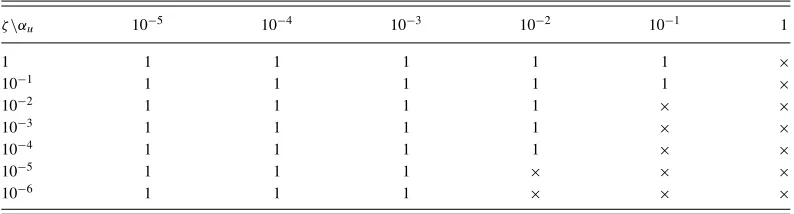
For example, for the case withαu=10−3,ζ =10−3, andA=4.382, there is a real eigenvalue, 4.543; the corresponding unstable eigenmode has non-zero total mass, in strong contrast to all the stable eigenmodes which have zero total mass. This result is typical for the stable solutions from the parameter rangeα3u < ζwithA>Acrit– the film volume is supercritical and, asα3u < ζ, this case lies in the parameter range where a surface-tension-smoothed-shock solution is feasible by the matching argument. We conjecture that all steady solutions found using the transient code are linearly stable to perturbations with zero total mass. To explore further, a series of tests was conducted, including increasing the number of grid points, comparing results from transient and steady-state numerical solvers, and comparing results across a range of values ofαuandζ. All eigenmodes with zero total mass were found to be stable: the region ofζ,αuparameter space for which solutions are stable with
TABLE III. Parameter map ofζandαuindicating number of eigenvalues with positive real part, forA=4.382.
ζ\αu 10−5 10−4 10−3 10−2 10−1 1
1 1 1 1 1 1 ×
10−1 1 1 1 1 1 ×
10−2 1 1 1 1 × ×
10−3 1 1 1 1 × ×
10−4 1 1 1 1 × ×
10−5 1 1 1 × × ×
10−6 1 1 1 × × ×
VII. FILM PROFILES WITH SIGNIFICANT MASS AND MOMENTUM TRANSFER AT THE SURFACE
With the c5 andc6 terms of (21) different from zero, the droplets transfer mass as well as momentum to the film flow. As before, the focus is on cases where the film is driven solely by the impacting droplets, i.e., the wall is stationary.
The parameter valuesc1 toc4, and the film volumeA, that have been shown previously (in Sec.V) to produce a stable steady solution whenc5,c6=0, are all fixed. Solutions with values of c5≤0 andc6≤0, corresponding to mass addition to the film from droplets travelling in the azimuthal and radial directions, respectively, are explored. Recall that, according to the distinguished-limit analysis, mass transfer can become as significant as momentum transfer by increasing the average density or increasing the inclination angle of the incoming droplets.
Whereas, in the steady model studied, there is no net mass flux into the film and the emphasis has been on the flow into the film through the surface and out of the film through the wall sink, there is nothing in principle to prevent mass leaving the film through its surface as well. On a backslope of the interface, the termauE∂h0/∂θis negative which might suggest that mass leaves the surface of the film. This flux should, however, be considered in conjunction with the positive term−avE, which, in the model, always adds mass to the film. Even when the gradient ofhis negative, mass will not leave if∂h0/∂θ > vE/uE, although the net flux into the film will be lower than when the gradient ofhis positive. For all of the cases considered herein the net local flux into the film is everywhere positive.
As previously, the evolution equation is solved numerically by a fully implicit backward-time-difference scheme, using theMATLABfunctionbvp4c. The code incorporates a single sink modelled numerically as a small finite section of the cylinder wall, across which there is a constant outflow of fluid. The outflow function used is
vcyl =
⎧ ⎪ ⎪ ⎨ ⎪ ⎪ ⎩
0 θ < θs, vout θs< θ < θe, 0 θe< θ,
(36)
where for the cases of a single sink located atθ=0,θs= −π/100, andθe=π/100 are used; in all casesucyl=0.
To study steady solutions, the total mass outflow is required to match the total mass inflow. The total mass entering the system is given by
2π
0 (c5
∂h
∂θ +c6) dθ=2πc6, (37)
sincehis 2π-periodic andc5andc6are constants, and the outflow velocity at the sink is
vout = 2π θe−θs
c6. (38)
θ
y
K
L
M
L’
M’
N
G
H
−3 −2 −1 0 1 2 3
[image:17.612.168.444.87.299.2]0 0.2 0.4 0.6 0.8 1 1.2 1.4 1.6
FIG. 7. Streamlines: sink atθ=0,a=10−6,u
E=102,vE= −104,A=4.382,ζ=10−3,αu=10−2,k=1, andβ=1.
In order to calculate residence times and to visualize the flow field, to check, for example, whether there is any recirculation, information on the streamlines is required. From(B21)and(B23), the leading-order streamfunctionψis
ψ= − c1
∂h0
∂θ + ∂3h
0
∂θ3
+c2sinθ
y3
6
+
c1 ∂
h0
∂θ + ∂3h
0
∂θ3
+c2sinθ
h0+c3∂ h0
∂θ +c4
y2 2 −
vcyl(θ)dθ. (39)
Figure 7 illustrates the steady-state streamlines when mass is extracted at a sink at θ =0,
a=10−6,u
E=102,vE = −104,A=4.382,ζ =10−3,αu=10−2,k=1, andβ=1. The surface profile for the corresponding dominant-droplet-momentum case (without a sink) withk=2 is shown in Figure5. By settingk=1, the droplet volume fraction in the core flow is increased and with all the other parameters fixed, the mass transfer is made as significant as momentum (see TableI) and results in the flow field shown in Figure7. The dip in the surface elevation as the film passes over the sink is similar to that found by Momoniatet al.37in the radial spreading under gravity and surface tension of a thin film under the influence of slot suction. By following a streamline, the path of a given fluid particle from its entry into the film surface until it exits at the sink can be traced – the path is shown by the thick black line in Figure7. The fluid entering the surface nearKgoes around the cylinder between 2 and 3 times before leaving at the sink atN. There is recirculation, in a small region betweenGandHat the cylinder wall aroundθ=1.
A. The effect of increasing droplet mass contribution
[image:17.612.147.502.393.452.2]−3 −2 −1 0 1 2 3 0
0.5 1 1.5 2 2.5
θ
h
c
5=0, c6=0 c
5=1e−05, c6=0.01 c
5=2e−05, c6=0.02 c
5=3e−05, c6=0.03 c
5=4e−05, c6=0.04 c
5=5e−05, c6=0.05 c
5=6e−05, c6=0.06 c
[image:18.612.167.451.89.322.2]5=7e−05, c6=0.07
FIG. 8. Film profileshwhenA=4.382, variousc5=10−3×c6. Other parameters arec1=10−4,c2= −1,c3=10−3,
c4=1,ucyl=0.
For fixedA=4.382 and increasing mass flow into and out of the film, the mass of fluid ahead of the sink increases to provide the required pressure head for the given outflow, and correspondingly the mass behind the sink decreases, see Figure8. For|c6| ≥4×10⁻²a backward-facing shock no longer features.
Figure9(a)shows the streamlines for a case with small droplet mass transfer whenA=4.382 andc6= −0.01. As in the case of dominant droplet momentum, there is a broad recirculation region, and stagnation points on the boundary. The injected fluid is resident for 3.5–4.5 cycles. Figure9(b)
illustrates streamlines for a film with the same film volume but much greater droplet mass input –c6= −0.07, the minimum for which a solution can be found – with a maximum residence of just over one cycle. In this case, so much fluid is built up on the upstream of the sink (θ <0) that there is no shock inθ >0.
−3 −2 −1 0 1 2 3
0 0.5 1 1.5 2 2.5
θ
y
−3 −2 −1 0 1 2 3
0 0.5 1 1.5 2 2.5
θ
y
(a) (b)
FIG. 9. Streamlines when (a)c5= −10−5,c6= −10−2, (b)c5= −7×10⁻⁵,c6= −7×10⁻², andA=4.382. Other
[image:18.612.111.509.528.700.2]−3 −2 −1 0 1 2 3 0
0.5 1 1.5 2 2.5 3 3.5 4 4.5
θ
h
[image:19.612.166.449.91.319.2]A=2.000 A=2.500 A=3.000 A=3.500 A=4.000 A=4.382 A=5.001 A=5.991
FIG. 10. Film profilehwhenc5= −10−5,c6= −10−2, variousA. Other parameters arec1=10−4,c2= −1,c3=10−3,
c4=1,ucyl=0.
B. The effect of film volumeA
Figure10shows the film profiles for a range ofA, the film volume per unit axial length, when droplet mass parameters are c5 = −10−5 andc6 = −10−2. Steady-state solutions were found for A=2.0 toA=5.991. In all cases, there is a small build up of fluid mass before the sink. Smooth profiles are obtained for lower values ofA, and, asAincreases, the profile develops a hump around θ =π/2, until a value ofA≈4.0, when it is close to the critical profile. A further increase in mass is incorporated into a backward-facing shock in 0< θ < π/2. The loss of mass through the sink makes the film thin immediately after θ =0; note that very thin films were difficult to compute. Continuation from nearby profiles was implemented, but no films were found withA<2.0. ForAmax
=5.991, the largest film volume for which a steady profile with these parameters could be obtained numerically, the shock is so close to the sink that the capillary wave at its foot is close to interacting with the film hump before the sink. This result demonstrates the sharp change that results from the inclusion of mass transfer, sinceA→ ∞when it is absent (cf.(27)).
C. The effect of sink position
In designing an engine bearing chamber, it may be possible to re-position the sink through which oil leaves the chamber. Thus far we have assumed that the sink is at the bottom of the cylinder, atθ=0; other sink positions are now examined to establish how varying the sink position affects the film. For all the simulations in this section, the parameters areA=4.382,c1=10−3,c2= −1, c3=10−2c4=1,c5= −10−4,c6= −10−2, andvcylis defined by(38)for different values of sink position.
−2 0 2 0 0.5 1 1.5 2 2.5 θ y
sink at θ = −3π/4
−2 0 2
0 0.5 1 1.5 2 2.5 θ y
sink at θ = −π/2
−2 0 2
0 0.5 1 1.5 2 2.5 θ y
sink at θ = −π/4
−2 0 2
0 0.5 1 1.5 2 2.5 θ y
sink at θ = 0
−2 0 2
0 0.5 1 1.5 2 2.5 θ y
sink at θ = π/4
−2 0 2
0 0.5 1 1.5 2 2.5 θ y
sink at θ = 1
−2 0 2
0 0.5 1 1.5 2 2.5 θ y
sink at θ = 1.17
−2 0 2
0 0.5 1 1.5 2 2.5 θ y
sink at θ = 1.25
−2 0 2
0 0.5 1 1.5 2 2.5 θ y
sink at θ = 1.30
−2 0 2
0 0.5 1 1.5 2 2.5 3 θ y
sink at θ = 1.35
−2 0 2
0 0.5 1 1.5 2 2.5 3 θ y
sink at θ = π/2
−2 0 2
0 0.5 1 1.5 2 2.5 θ y
[image:20.612.123.493.81.636.2]sink at θ = 3π/4
FIG. 11. Streamlines for various sink positions. Parameters arec1=10−3,c2 = −1,c3=10−2,c4=1,c5= −10−4,
c6−10−2,A=4.382.
VIII. CONCLUSIONS
In this study, a model of a two-dimensional liquid film flowing around the inside boundary of a moving or stationary smooth rigid circular cylinder has been developed in the case when there is a dilute two-phase flow in the core of the cylinder and a strong interaction with droplets of the same liquid impacting on the free surface. The bulk flow of the film is taken as Newtonian and laminar and the central core of two-phase flow to be inviscid. Interface conditions based on conservation of mass and momentum have been derived.
Estimates of appropriate physical parameters to determine scalings and the development of simplified film models through distinguished limits are presented. In particular, the fact that the film has small aspect ratio (film thickness to azimuthal length scale) is exploited to simplify greatly the governing equations and boundary conditions. Various parameter ranges for the droplets are identified, and in each case the corresponding governing equation for the film evolution is derived. A single evolution equation for the film profile,(21),
∂h
∂t +
∂
∂θ c1 ∂ h
∂θ + ∂3h
∂θ3
h3
3 +c2sinθ
h3
3 + c3(θ) ∂h
∂θ +c4(θ)
h2 2
+ c5(θ)
∂h
∂θ +c6(θ)
+ ∂
∂θ
ucylh
−vcyl =0,
is obtained from which specific cases can be obtained by appropriate choice of coefficients. Thec1coefficient may be small but, being a function of Wef, is independent of other coefficients and it is retained in order to study its effect, since it acts on the highest derivative ofh. The term involvingc2corresponds to the contribution of gravity. The coefficientc4in the droplet momentum is identical in all cases and is analogous to an imposed shear on the surface, such as that studied by Villegas-D´ıazet al.12
The term with coefficient c3 is analogous to the temperature-dependent surface-tension term that arises in the problem of flow down a heated plane, see Thiele and Knobloch.38The termsc
5and c6 arise from the contribution of droplet mass flux. The derivative term arises from the azimuthal component of droplet mass, and the constant term from the radial component.
In this study the focus is on cases where the impact velocity of droplets into a film is sufficiently high for the droplet momentum to drive the motion of the film in the absence of rotation of the cylinder wall.
To fix on the key terms of surface tension and droplet momentum, the equation was re-scaled and a new set of coefficients,c1 =ζ,c2 = −1,c3 =αu,c4 =1,c5 =0,c6 =0, in(21). When
ζ,αu = 0, the flux equation reduces to a cubic, which has at most two positive real solutions, depending onA, the volume of the film. WhenA≤Ac=3.9509, there is a single completely wetting solution for the film. WhenA>Ac, shock solutions may occur, with the mass in excess of critical accumulating in a shock somewhere in 0< θ < π.
A matching argument suggests that, for ζ,αu >0, only certain combinations of shocks are mathematically feasible. Ifα3
u ≤ O(ζ) asζ →0, smoothed backward- and forward-facing shocks located in 0 < θ < π are feasible; ifζ α3
u1 asαu →0, a smoothed forward-facing shock located in π/2< θ < π is feasible. Kinematic wave theory suggests that profiles with a single backward-facing shock in the lower quadrant (0 < θ < π/2) are stable, profiles with a single forward-facing shock in the upper quadrant (π/2< θ < π) unstable, and profiles featuring multiple shock solutions may be stable (unstable) if the profile height is decreasing (increasing) asθincreases throughπ/2.
These results are strongly supported by the numerical results obtained from a transient solver. Linear stability analysis confirmed the theoretical and transient-solver results and highlighted the significance of theζ =α3
uboundary in parameter space. Interestingly, the stability analysis revealed positive real eigenvalues, and hence the existence of potentially unstable perturbation modes. On closer examination, however, the modes were found not to be mass-conserving in the sense that a system of fixed mass fraction cannot admit such modes.
flux) in the film-height evolution equation(21). The values ofc5andc6were varied independently but in such a way that they were consistent, in terms of the physics, withc3andc4. Having chosen a set of coefficientsc1toc4andAfor which momentum-dominant steady-state solutions are known to be stable, mass transfer effects were considered by includingc5 andc6. In order to achieve a steady-state condition, the film volume,A, is kept constant by introducing a sink at the cylinder wall. Whenc5andc6are constant, as in the cases considered in this study, the mass entering the system is linearly proportional toc6and the strength of the sink is therefore trivial to determine. Plots of the calculated streamlines reveal the underlying steady-flow behaviour and enable the residence time of fluid that enters through the film surface to be determined. Importantly from the perspective of oil degradation, closed recirculation zones that never receive fresh fluid feature behind the main shock structures. The extent of this closed recirculation can be diminished, but not eliminated, by re-positioning the sink to lie beneath the shock.
On increasing the mass flux through the film, i.e., increasing the value ofc6, the mass of fluid ahead of the sink increases to provide the required pressure head for the required balancing outflow; correspondingly, the mass behind the sink decreases. It was observed that an increase in droplet mass flux reduces the footprint of the backward-facing shock and recirculation zone.
The effect ofc5is more subtle. By increasingc5substantially, steady-state solutions may cease to exist, as has been reported previously in cases of a film on a rotating wall without droplet impact. It was found thatAcrit, the film volume above which a shock solution is required, and Amax, the maximum film volume sustained by a stable steady shock solution, are dependent onc5.
In the film evolution equation (21) the termsc5∂h/∂θ anducyl∂h/∂θ have the same form in
h and are therefore interchangeable if the film height profile h is of interest. However, the first form arises from the azimuthal mass contribution at the film surface, and the second from the rotating wall boundary condition. Therefore, they are distinct in the calculation of the underlying film velocitiesuandv, and the two flows withc5=0,ucyl =0, andc5 =0,ucyl =0 have distinct behaviours.
ACKNOWLEDGMENTS
The authors wish to acknowledge the financial support provided by Rolls-Royce plc, Aerospace Group as part of University Technology Centre in Gas Turbine Transmission Systems at the Univer-sity of Nottingham. The views expressed in this paper are those of the authors and not necessarily those of Rolls-Royce plc, Aerospace Group. The authors would like to thank one of the referees for very careful reading of the article and helpful feedback.
APPENDIX A: CONSERVATION OF MASS AND MOMENTUM ACROSS THE FLUID INTERFACE
Consider conservation of mass and momentum near the surface separating the two-phase flow of air and droplets and the film flow (in reality the two flows are separated by a complex, nar-row transitional layer, which is modelled as a simple surface, see Edwardset al.39). This interface is represented as a moving surface, a surface at which density and velocity are discontinuous and mass and momentum transfer across it (see Slattery40). Consider a material pillbox strad-dling the moving and deforming interface between the two-phase flow and the fluid film; the pillbox has endcaps of small arbitrary length parallel to the interface, and thicknessδ across the interface.
1. Conservation of mass
Mass conservation in the control volumeVE∪VI gives
D Dt
VE(t)
ρEdV +
D Dt
VI(t)
ρIdV =0. (A1)
By using Reynolds’s transport theorem and takingρE=αρ andρI=ρ, the above two terms on the left-hand side can be rewritten as
VE(t) ∂(αρ)
∂t +
∂(αρuj) ∂xj
dV and
VI(t) ∂ρ ∂t +
∂(ρuj) ∂xj
dV, (A2)
or, on using Gauss’s theorem,
VE(t) ∂(αρ)
∂t dV +
SE(t)
αρujn˜jdS and
VI(t) ∂ρ ∂t dV +
SI(t)
ρujn˜jdS, (A3)
where SE(t)andSI(t) are the surface areas enclosingVE(t) andVI(t), respectively, and ˜nj denotes the normal pointing out of the volume. In the limitδ→0, the volumetric integrals vanish and these two expressions reduce to
Si nt(t)
αρ(uE jnj−Ujnj) dS (A4)
and
Si nt(t)
ρ(Ujnj−uI jnj) dS, (A5)
where Sint is the common surface at the interface between the two volumes,Uj is the interface velocity, andnjdenotes the normal to the interface pointing into the two-phase flow.
The velocity fields may not be continuous across the interface: letuEj/uIjdenote the respective limiting forms of the two-phase/film velocity fields at a point approaching Sint from within the respective volumes.
Re-combining(A4)and(A5), we obtain
Si nt(t)
[ρ(1−α)Ujnj+ρ(αuE j−uI j)nj] dS=0. (A6)
Since the interface segmentSintis arbitrary,
ρ(α−1)Ujnj =ρ(αuE j−uI j)nj. (A7)
2. Conservation of momentum
Applying the principle of conservation of momentum to the two volumes defined above, we obtain
D Dt
VE(t)
αρuidV =
VE(t)
αρgidV+
SE(t)\Si nt(t)
Ti jn˜jdS+
Si nt(t)
TEi jn˜jdS (A8)
and D Dt
VI(t)
ρuidV =
VI(t)
ρgidV +
SI(t)\Si nt(t)
Ti jn˜jdS+
Si nt(t)
TI i jn˜jdS. (A9)