Abstract—In this paper, development of a drone system to inspect social infra structure and its control system are explained. Obtaining absolute position with GPS is a fundamental method widely utilized in applications of a drone flying in the air because it provides sufficient performance required for autonomous flight. However, it cannot be used when a drone is moving near a building because of multi-paths and occlusion problems of radio signals from satellites. Particularly, a drone for inspection task of social infrastructure is required to have capability of autonomous flight near buildings for efficient work and safety. As the essential function for that, an algorithm to estimate the position of vehicle itself is investigated and embedded to the developed system. A 3D depth camera was employed to get both depth and image data of environment surrounding the vehicle. The position estimation carried out with SLAM (Simultaneous Localization and Mapping) algorithm using depth information is introduced. Besides, a controller to move the drone autonomously based on the position information was also developed. The system has been evaluated through several experiments.
Index Terms—Autonomous flight, Drone, Depth Camera, Inspection Task
I. INTRODUCTION
AINTAINING old and deteriorated infrastructures such as bridge and tunnel is one of important issues in many countries having a lot of artificial civil and industrial constructions. For the case of Japan, about 700,000 bridges have been constructed and used. Lots of them are made in the period of rapid growth. It was reported that, in 2010, 50 years had elapsed since about 8% of them had been constructed. Moreover, it is expected that about 26 % in 2020, and 53% of them in 2030, respectively, will be considered deteriorated bridges with ages of more than 50 years [1]. Likewise, rapid deterioration of physical social infrastructure, including bridges, is recognized as a big problem in Japan. Old infrastructures require a huge maintenance cost. For example,
Manuscript received December 8, 2017; revised February 11, 2018. This work was supported by NEXCO Group Companies’ Support Fund to Disaster Prevention Measures on Expressways.
S. Kawabata and K. Nohara are with Department of Mechanical Engineering, Faculty of Engineering, Ehime University, Matsuyama, Ehime, Japan.
J. H. Lee is with Department of Mechanical Engineering, Graduate School of Science and Engineering, Ehime University, 3 Bunkyo-cho, Matsuyama, Ehime 790-8577, Japan (corresponding author to provide phone: 81-89-927-9709; e-mail: [email protected]).
H. Suzuki, T. Takiguchi, O. Park and S. Okamoto are with Department of Mechanical Engineering, Graduate School of Science and Engineering, Ehime University, Ehime, Japan.
every bridge should be checked through regular inspection whose period is set as one time per five years in the rule of Japanese government. The safety of the worker and the worker’s accessibility to the inspection area are recognized as the main difficulties in inspection tasks. At the same time, if the public road is temporarily prohibited for safety inspection or maintenance task, it also causes another economic damage in the industries or businesses related to that road.
Therefore, many researches have been carried for effective inspection tasks. Particularly, robotics technology also has been attracting attention from researchers because it is recognized as a solution for these problems. Some robotic systems equipped with special capabilities of wall climbing or robotic arm to access high places have been investigated in these days. Especially, several types of multi-rotor crafts have been developed for effective inspection processes because they show high performance in mobility to access target positions [2-4]. Recently, experimental tests with unmanned aerial vehicles (UAVs) for bridge inspection have been carried out field situations [5].
The most important capability of a multi-rotor craft for inspection applications is stable hovering near a target position. Namely, the rotorcraft should have the capability of stable flight in a high place near the bridge for inspection tasks such as taking pictures. However, the fatal drawback while using a multi-rotor craft is the fact that it is sensitive to wind. In high places near the structure, sometimes there are complex and strong winds, so the rotorcraft cannot keep its posture and may collide with the structure. In addition, the fundamental limitation of a UAV is that, it cannot access the ceiling surface of bridge structure or a building. For this reason, robots having the capability of adhering to the ceiling or wall have got an attention from the robotics research society [6-9]. So far, their fundamental limitation is that they can move only on the face of the wall, and cannot fly in the air. Thus, it is impossible to move directly to the task position. To cope with the above-mentioned problems, a novel rotorcraft was proposed in our previous research [10]. In addition to the basic flying functions of a conventional rotorcraft, a special device to provide the capabilities for adhering to and moving on the ceiling was installed in the developed system. For this purpose, a specialized frame with active wheels was designed. Additionally, experimental tests were carried out with the developed prototype system.
General drones show an excellent performance in navigating to the goal position through free space in the air because they are supported by GPS sensor system providing sufficient position information and good motion control
Autonomous Flight Drone with Depth Camera
for Inspection Task of Infra Structure
Shinya Kawabata, Kodai Nohara, Jae Hoon Lee, Hirotatsu Suzuki, Takeaki Takiguchi, Oh Seong Park,
and Shingo Okamoto
technology based on the measurement. However, GPS cannot be used when a drone is located near to a building because correct position information cannot be provided owing to multi-paths problem of radio signals from satellites, or lack of number of satellites being detected by the sensor. In other words, some signals from satellites are reflected or covered by wall of buildings or structures, or enough number of signals cannot be taken because buildings obscure the GPS transceiver, correct position information cannot be obtained resultantly.
As a solution to solve the above positioning problem, a positioning technology with depth camera sensor which does not rely on typical GPS information is investigated in our previous research [11]. The proposed method processes depth data with SLAM algorithm for obtaining the position of vehicle in real time manner. In this research, a drone system embedded with the proposed method was developed and some experimental works to confirm its usability were carried out.
This paper is organized as follows. In section 2, the configuration of the drone system developed in this research is explained. The algorithm for autonomous navigation using the position information obtained with SLAM algorithm and depth camera is addressed in section 3. Some results of position estimation and flying is given in section 4. Finally, conclusions and future works are addressed in section 4.
II. DEVELOPMENT OF DRONE SYSTEM FOR INSPECTION TASK
A. Configuration of Drone System
The drone system that was developed for inspection task of infrastructure in this research is displayed in Fig. 1. The width of the vehicle including propeller guard for safety is about 1 [m], and the height is about 0.15 [m], respectively. Four propellers of 10 [inch] in diameter were employed in the system. The maximum lifting force of the system is about 2.93 [kgf]. So it provides sufficient power to generate lifting force to equip components such as depth camera, main computer,
and battery and so on. Additional to body frame, safety guard of carbon material having square section are attached to the body for keeping off sudden collision between propeller and wall. A lithium-polymer battery having large charge capacity of 4000 [mAh] was employed as main power source embedded in the system. The total weight of the system including battery is about 1.3 [kgf].
B. Control Hardware
Schematic of the control hardware for the developed system is displayed in Fig. 2. It mainly consists of two parts, rotorcraft and transmitter that are connected with each other via wireless communication channel. The transmitter has two joysticks for generating parameters of four user command. Generally they are angular rates of three pose parameters of vehicle body, i.e., roll, pitch, and yaw, and throttle for regulating lifting force.
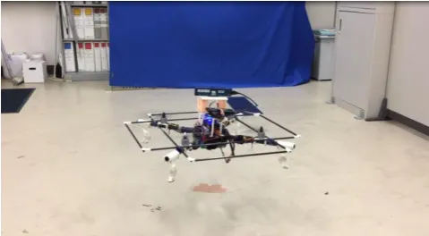
[image:2.595.304.549.430.772.2]The drone includes a flight controller embedded with IMU sensors, four motors to rotate propellers, four drivers so-called ESC to provide power to motors according to control command from flight controller, companion computer, depth camera, and receiver of wireless communication and so on. The depth camera [12] displayed in Fig. 4 is connected to the companion computer which manipulates 3D depth information and computes vehicle position with SLAM algorithm. As a flight controller being in charge of measurement of body posture and motion control, Pixhawk manufactured by 3D Robotics corporation was employed in the system [13]. It includes various sensors such as
Fig. 1. Top view of the drone system developed in this research
Fig. 2. Control hardware of the drone system
[image:2.595.49.286.550.773.2]acceleration sensor, gyro sensor, compass, and barometer for measurement of body posture and height. Besides, telemetry for monitoring with remote computer can be attached. For autonomous navigation, the companion computer plays a role of high level controller to generate motion command based on the position. The flight controller controls the drone’s posture by changing the speed of motors according to the motion command from the companion computer.
C. Control Modes
Two control modes of manual and autonomous control were prepared in the developed system. When the system is operated in manual control mode, motion command is made by user’s joystick manipulation on the transmitter. So it is appropriate such operations when the drone is not far from an
operator so can be seen well, besides there is no obstacles in the area near itself.
On the other hand, autonomous control mode is managed by the companion computer which is embedded in the vehicle. The companion computer generates motion command autonomously based on both the user command and the information obtained with the depth camera. As the companion computer, a StickPC manufactured by Intel corporation was utilized, where Linux OS of Ubuntu 16.04 was installed in it.
D. Depth Camera
As a main sensor to detect surrounding environment of the drone, a depth camera of RealSense ZR300 manufactured by Intel corporation was employed in the developed system. It is equipped with an IR camera to capture 3D depth image, a RGB camera, a fisheye camera, IMU module having three axes acceleration and three axes gyro sensors and so on [13]. It is connected to companion computer through high speed USB 3.0 communication channel. The depth camera and its coordinate system are displayed in Fig. 4. An example of RGB image and 3D depth image captured for the same scene by RealSense depth camera is shown in Fig. 5. Where the distance from the sensor to the objects is depicted with greyscale pixels in the depth image; white for short and black for long distances from the camera, respectively. In addition, it is usually obtained as noisy image having some parts cannot be detected well according to optical conditions. Therefore, it is required surely to have robustness to noise for generating stable position output.
III. AUTONOMOUS FLIGHT CONTROL
A. Positioning with SLAM Algorithm
For providing stable position information of drone itself, SLAM algorithm was utilized in this research. In most cases of inspection task, 3D map for autonomous navigation is not provided. So the drone is required to have capability of both making map near the target position and estimating its position. Therefore, SLAM technology is appropriate for this application. SLAM software library for RealSense ZR300 depth camera developed by Intel corporation was employed in this research for map building and localization. It updates position information 30 times per a second with sensor data of depth camera.
For an example in real application of inspection tasks, a strategy can be considered as a potential scenario such that after making map through pre-flying near a target position by manual operation, autonomous inspection task can be performed based on the map and a planned path in it.
B. Flight Control Using Companion Computer with
Position Information
[image:3.595.48.290.254.772.2]When the system is operated in autonomous control mode, the companion computer generates motion command with navigation algorithm such as path tracking based on the position information. Then the motion command is sent to Fig. 4. Depth camera and its coordinate system [12]
(a)RGB image data
(b) Depth image data
flight controller of Pixhawk by using MAVLink protocol through wired serial communication channel [14].
The drone is flying in free space, so its motion degree of freedom is six. However, its motion is controlled by changing
rotation speed of four propellers. For general drone systems, pose and position cannot be controlled independently because of its geometric structure. Therefore, the translational motion in horizontal space is controlled by changing the pose of the drone, i.e., rotation in roll and pitch axes. Then, the rotational motion in yaw axis, namely change of heading direction, is controlled by modulating the rate between both two pairs of propellers in diagonal position. Finally, the vertical motion is controlled by changing the average rotation speed of all propellers.
In the developed system, the translational motions according to z- and x-axis of depth camera coordinate system in Fig. 4 are controlled by changing roll and pitch angle, respectively. The rotational motion according to y-axis of depth camera coordinate system is controlled by changing yaw angle. Finally, the vertical motion to change altitude of the drone is performed by changing throttle value. Therefore, four input parameters decided for keeping reference position is given from the companion computer to the flight controller of the drone with the same frequency of the depth camera resultantly.
IV. EXPERIMENTAL WORKS
A. Position Estimation Experiment
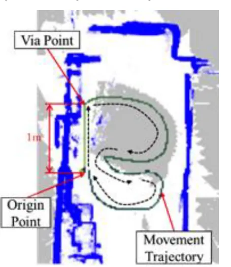
Experimental works to confirm the capability of map building and position estimation, were conducted with the developed system using depth camera and software library of SLAM algorithm. Fig. 6 shows the environment for position estimation experiment. The system started the linear motion from the origin point to via point. After arriving to the via point through linear motion from the origin point, it moved back to the origin point according to circular trajectory. The resultant position estimated by the developed system with SLAM algorithm is depicted in Fig. 7. Where the solid line of green color denotes the trajectory where the system moved, and blue points denote the horizontal map built during the experiment that are depicted with dashed lines in Fig. 6. It is observed that the map built during the experiment is also roughly fit to the real experimental environment. Besides, the computation result is mostly coincident to the real motion trajectory.
The coordinate estimated by the developed method when the system was located at the via point was (x, y, z) = (0.02,-0.02,1.08) [m], while the actual coordinate is (x, y, z) = (0,0,1) [m], thus there occurred about 8 [cm] error in z direction. After coming back to the origin point, the coordinate of the system was (x, y, z) = (-0.04,0.00,-0,04) [m] in the experiment. Through the experimental work, although there occurs coordinate errors a little in some cases, it was confirmed that the system with SLAM algorithm provides position information sufficient for autonomous flight near building.
[image:4.595.47.290.109.292.2]Nextly, tracking performance of the developed system during manual movement was checked. It was confirmed that the system can track drone’s motion robustly and the position information is usable for autonomous flight as shown in Fig. 8.
[image:4.595.49.277.299.562.2]Fig. 6. Environment of position estimation experiment
Fig. 7. Map of the experimental environment of Fig. 6 that was constructed with the developed system including SLAM algorithm, where the movement trajectory of the drone is depicted with solid line
[image:4.595.48.271.606.770.2]B. Experiment of Flight Control Using Companion Computer with Position Information
Firstly, motion control in manual flight was tested by operation using transmitter. After the control parameters of the flight controller has been tuned, stable motion was obtained resultantly as displayed in Fig. 9. Then, experiment of automatic flight was carried out where the motion command was generated by the companion computer based on the position information from SLAM algorithm with depth camera. As shown in Fig. 10, it is observed that the drone could fly and keep hovering according to the position information captured in real time.
V. CONCLUSION AND FUTURE WORK
A drone system for infrastructure inspection task was developed in this research. As potential solution to cope with difficulty in positioning near to buildings, a method by using SLAM algorithm with 3D depth camera was investigated and tested experimentally. Besides, it was confirmed that the developed system with the proposed positioning and autonomous flight method is applicable to autonomous flight for inspection task.
As future work, researches of control algorithm for autonomous flight in real fields of outdoor environment is now ongoing.
REFERENCES
[1] Ministry of Land, Infrastructure, Transport and Tourism, The maintenance of national road network in Japan (2009)
[2] L. Wallace, A. Lucieer, C. Watson, and D. Turner, Development of a UAV-LiDAR System with Application to Forest Inventory, Remote Sensing, Vol. 4, No. 6 (2012)
[3] P. Liu, A.Y. Chen, Y.-N. Huang, J.-Y. Han, J.-S. Lai, S.-C. Kang, T.-H. Wu, M.-C. Wen, and M.-H. Tsai, A Review of Rotorcraft Unmanned Aerial Vehicle Developments and Applications in Civil Engineering, Smart Structures and Systems, Vol. 13, No. 6 (2014)
[4] C. Deng, S. Wang, Z. Huang, Z. Tan, and J. Liu, Unmanned Aerial Vehicles for Power Line Inspection: A cooperative Way in Platforms and Communications, Journal of Communications, Vol. 9, No. 9 (2014)
[5] Barritte Lovelace, Principal Investigator Collins Engineers Inc., Unmanned Aerial Vehicle Bridge Inspection Demonstration Project, Research Project Final Report (2015)
[6] J.C. Grieco, M. Prieto, M. Armada, P. Gonzales de Santos, A Six-Legged Climbing Robot for High Payloads, Proceeding of the IEEE International Conference on Control Applications, pp.446- 450 (1998)
[7] D. Schmidt, C. Hillenbrand and K. Berns, Omnidirectional locomotion and traction control of the wheel-driven, wallclimbing robot, Cromsci, Robotica, Vol. 29, No. 7, pp.991-1003 (2011)
[8] Kiyoshi Tsuru, S. Hirose, Development of Vmax III: Magnetic Wall Climbing Robot with Holonomic and Omni-directional Mobility, Journal of the Robotics Society of Japan, Vol. 30, pp.639-647, (2012)
[9] I.-G. Koo, T.-D. Trong, Y.-H. Lee, H. Moon, J. Koo, S.-K. Park, H.-R. Choi, Development of Wall Climbing Robot System by Using Impeller Type Adhesion Mechanism, Journal of Intelligent and Robotic System, Vol. 72, No. 1, pp.57-72 (2013)
[10] S. Kawabata, H. Suzuki, T. Takiguchi, O. S. Park, J. H. Lee, and S. Okamoto, Development of Autonomous Flight Drone for Inspection Task and Experimental Evaluation of Its Position Estimation System Using Depth Camera, Proceedings of AROB 23rd, pp.951-955 (2018) [11] M. Yasunaga, J. H. Lee, and S. Okamoto, Prototype Design and Experimental Test of a Rotorcraft Capable of Adhering to and Moving on the Ceiling, Proceedings of 7th International Conferennce on
Mechatronics and Manufacturing, ICMM (2016) [12] Intel co., Intel RealSense 3D Camera ZR300,
https://software.intel.com/en-us/realsense/zr300 [13] PX4 autopilot, https://pixhawk.org
[image:5.595.47.289.58.232.2][14] QGROUNDCONTROL, MAVLink, http://qgroundcontrol.org/mavlink/start Fig. 9. Resultant movement in experiment of testing manual flight of the
developed system
[image:5.595.47.287.267.399.2]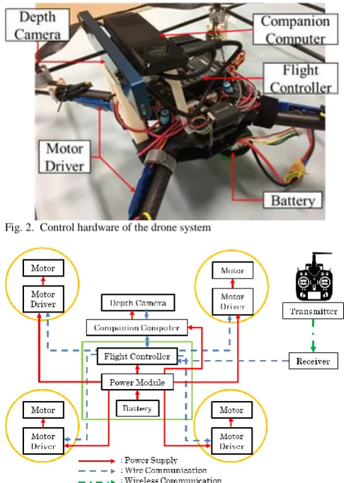
![Fig. 4. Depth camera and its coordinate system [12]](https://thumb-us.123doks.com/thumbv2/123dok_us/409629.538494/3.595.48.290.254.772/fig-depth-camera-coordinate.webp)