Structural Welding pdf
58
0
0
Full text
(2) Fabricators’ and Erectors’ Guide to Welded Steel Construction By Omer W. Blodgett, P.E., Sc.D. R. Scott Funderburk Duane K. Miller, P.E., Sc.D. Marie Quintana, P.E.. This information has been provided by The James F. Lincoln Arc Welding Foundation to assist the general welding industry.. The serviceability of a product or structure utilizing the type of information presented herein is, and must be, the sole responsibility of the builder/user. Many variables beyond the control of The James F. Lincoln Arc Welding Foundation or The Lincoln Electric Company affect the results obtained in applying this type of information. These variables include, but are not limited to, welding procedure, plate chemistry and temperature, weldment design, fabrication methods, and service requirements. This guide makes extensive reference to the AWS D1.1 Structural Welding Code-Steel, but it is not intended to be a comprehensive review of all code requirements, nor is it intended to be a substitution for the D1.1 code. Users of this guide are encouraged to obtain a copy of the latest edition of the D1.1 code from the American Welding Society, 550 N.W. LeJeune Road, Miami, Florida 33126, (800) 443-9353.. Copyright © 1999.
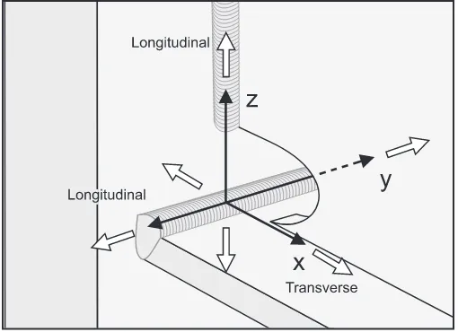
(3) Fabricators’ and Erectors’ Guide to Welded Steel Construction Table of Contents 1 Introduction . . . . . . . . . . . . . . . . . . . . . . . . . . . . . . . . . . . . . . . . . . . . . . . .1 2 Welding Processes . . . . . . . . . . . . . . . . . . . . . . . . . . . . . . . . . . . . . . . . . . . .1 2.1 SMAW . . . . . . . . . . . . . . . . . . . . . . . . . . . . . . . . . . . . . . . . . . . . . . .1 2.2 FCAW . . . . . . . . . . . . . . . . . . . . . . . . . . . . . . . . . . . . . . . . . . . . . . . .3 2.3 SAW . . . . . . . . . . . . . . . . . . . . . . . . . . . . . . . . . . . . . . . . . . . . . . . . .6 2.4 GMAW . . . . . . . . . . . . . . . . . . . . . . . . . . . . . . . . . . . . . . . . . . . . . . .8 2.5 ESW/EGW . . . . . . . . . . . . . . . . . . . . . . . . . . . . . . . . . . . . . . . . . . .10 3. Welding Process Selection . . . . . . . . . . . . . . . . . . . . . . . . . . . . . . . . . . . .11 3.1 Joint Requirements . . . . . . . . . . . . . . . . . . . . . . . . . . . . . . . . . . . . .11 3.2 Process Capabilities . . . . . . . . . . . . . . . . . . . . . . . . . . . . . . . . . . . . .12 3.3 Special Situations . . . . . . . . . . . . . . . . . . . . . . . . . . . . . . . . . . . . . .12. 4. Welding Cost Analysis . . . . . . . . . . . . . . . . . . . . . . . . . . . . . . . . . . . . . . .14. 5. Welding Procedures . . . . . . . . . . . . . . . . . . . . . . . . . . . . . . . . . . . . . . . .15 5.1 Effects of Welding Variables . . . . . . . . . . . . . . . . . . . . . . . . . . . . . .15 5.2 Purpose of Welding Procedure Specifications (WPSs) . . . . . . . . . . .17 5.3 Prequalified Welding Procedure Specifications . . . . . . . . . . . . . . . .18 5.4 Guidelines for Preparing Prequalified WPSs . . . . . . . . . . . . . . . . . .20 5.5 Qualifying Welding Procedures By Test . . . . . . . . . . . . . . . . . . . . . .20 5.6 Examples . . . . . . . . . . . . . . . . . . . . . . . . . . . . . . . . . . . . . . . . . . . .22 5.7 Approval of WPSs . . . . . . . . . . . . . . . . . . . . . . . . . . . . . . . . . . . . . .22. 6. Fabrication and Erection Guidelines . . . . . . . . . . . . . . . . . . . . . . . . . . .23 6.1 Fit-Up and Assembly . . . . . . . . . . . . . . . . . . . . . . . . . . . . . . . . . . . .23 6.2 Backing and Weld Tabs . . . . . . . . . . . . . . . . . . . . . . . . . . . . . . . . . .23 6.3 Weld Access Holes . . . . . . . . . . . . . . . . . . . . . . . . . . . . . . . . . . . . .24 6.4 Cutting and Gouging . . . . . . . . . . . . . . . . . . . . . . . . . . . . . . . . . . . .25 6.5 Joint and Weld Cleaning . . . . . . . . . . . . . . . . . . . . . . . . . . . . . . . . .25 6.6 Preheat and Interpass Temperature . . . . . . . . . . . . . . . . . . . . . . . . . .25 6.7 Welding Techniques . . . . . . . . . . . . . . . . . . . . . . . . . . . . . . . . . . . . .26 6.8 Special Welding Conditions . . . . . . . . . . . . . . . . . . . . . . . . . . . . . . .29 6.9 Weld Metal Mechanical Properties . . . . . . . . . . . . . . . . . . . . . . . . . .29 6.10 Intermixing of Weld Deposits . . . . . . . . . . . . . . . . . . . . . . . . . . . . .33.
(4) 7. Welding Techniques and Variables . . . . . . . . . . . . . . . . . . . . . . . . . . . . .35 7.1 SMAW . . . . . . . . . . . . . . . . . . . . . . . . . . . . . . . . . . . . . . . . . . . . . .35 7.2 FCAW-ss . . . . . . . . . . . . . . . . . . . . . . . . . . . . . . . . . . . . . . . . . . . . .36 7.3 FCAW-g . . . . . . . . . . . . . . . . . . . . . . . . . . . . . . . . . . . . . . . . . . . . .37 7.4 SAW . . . . . . . . . . . . . . . . . . . . . . . . . . . . . . . . . . . . . . . . . . . . . . . .38 7.5 GMAW . . . . . . . . . . . . . . . . . . . . . . . . . . . . . . . . . . . . . . . . . . . . . .39 7.6 ESW/EGW . . . . . . . . . . . . . . . . . . . . . . . . . . . . . . . . . . . . . . . . . . .40. 8. Welder Qualification . . . . . . . . . . . . . . . . . . . . . . . . . . . . . . . . . . . . . . . .40. 9. Weld Cracking . . . . . . . . . . . . . . . . . . . . . . . . . . . . . . . . . . . . . . . . . . . .40 9.1 Centerline Cracking . . . . . . . . . . . . . . . . . . . . . . . . . . . . . . . . . . . . .41 9.2 Heat Affected Zone Cracking . . . . . . . . . . . . . . . . . . . . . . . . . . . . . .42 9.3 Transverse Cracking . . . . . . . . . . . . . . . . . . . . . . . . . . . . . . . . . . . .44. 10 Weld Quality and Inspection . . . . . . . . . . . . . . . . . . . . . . . . . . . . . . . . .44 10.1 Weld Quality . . . . . . . . . . . . . . . . . . . . . . . . . . . . . . . . . . . . . . . . . .44 10.2 Weld Quality and Process-Specific Influences . . . . . . . . . . . . . . . . .46 10.3 Weld Inspection . . . . . . . . . . . . . . . . . . . . . . . . . . . . . . . . . . . . . . . .46 11 Arc Welding Safety . . . . . . . . . . . . . . . . . . . . . . . . . . . . . . . . . . . . . . . . .49.
(5) Fabricators’ and Erectors’ Guide to Welded Steel Construction 1. Introduction/Background. and not The Lincoln Electric Company, to specify the requirements for a particular project. The prerogative to specify alternate requirements is always within the authority of the Engineer of Record and, when more restrictive requirements are specified in contract documents, compliance with such requirements would supersede the preceding recommendations. Acceptance of criteria by the Engineer of Record that are less rigorous than the preceding does not change the recommendations of The Lincoln Electric Company.. This Fabricators’ and Erectors’ Guide to Welded Steel Construction has been produced by The Lincoln Electric Company in order to help promote high quality and costeffective welding. This guide is not to be used as a substitute for the AWS D1.1 Structural Welding Code, or any other applicable welding code or specification, and the user bears the responsibility for knowing applicable codes and job requirements. Rather, this document incorporates references to the D1.1-96 code, and adds explanation, clarification, and guidelines to facilitate compliance with the code. At the time of writing, this guide reflects the current industry views with respect to steel fabrication, with specific emphasis on the new provisions that have been recently imposed for fabrication of structures designed to resist seismic loads. These provisions are largely drawn from the Federal Emergency Management Administration (FEMA) Document No. 267, produced by the SAC Consortium, whose members include the Structural Engineers Association of California, Applied Technology Council, and California Universities for Research and Earthquake Engineering. Another cited document is the AWS D1 Structural Welding Committee’s Position Statement on the Northridge earthquake. Research is still underway, and additional provisions may be found that will further increase the safety of welded steel structures. The user of this document must be aware of changes that may occur to codes published after this guide, specific job requirements, and various interim recommendations that may affect the recommendations contained herein.. 2. Welding Processes. A variety of welding processes can be used to fabricate and erect buildings. However, it is important that all parties involved understand these processes in order to ensure high quality and economical fabrication. A brief description of the major processes is provided below. 2.1 SMAW. The January 1994 Northridge earthquake revealed a number of examples of lack of conformance to D1.1 code mandated provisions. Lack of conformance to code provisions, and the poor workmanship revealed in many situations, highlight the need for education. This document is one attempt to assist in that area.. Shielded metal arc welding (SMAW), commonly known as stick electrode welding or manual welding, is the oldest of the arc welding processes. It is characterized by versatility, simplicity and flexibility. The SMAW process commonly is used for tack welding, fabrication of miscellaneous components, and repair welding. There is a practical limit to the amount of current that may be used. The covered electrodes are typically 9 to 18 inches long, and if the current is raised too high, electrical resistance heating within the unused length of electrode will become so great that the coating ingredients may overheat and “break down,” potentially resulting in weld quality degradation. SMAW also is used in the field for erection, maintenance and repairs. SMAW has earned a reputation for depositing high quality welds dependably. It is, however, slower and more costly than other methods of welding, and is more dependent on operator skill for high quality welds.. The information contained herein is believed to be current and accurate. It is based upon the current technology, codes, specifications and principles of welding engineering. Any recommendations will be subject to change pending the results of ongoing research. As always, it is the responsibility of the Engineer of Record,. The American Welding Society (AWS) publishes a variety of filler metal specifications under the jurisdiction of the A5 Committee; A5.1 addresses the particular requirements for mild steel covered electrodes used with the shielded metal arc welding process. The specification A5.5 similarly covers the low alloy electrodes.. 1.
(6) For welding on steels with minimum specified yield strengths exceeding 50 ksi, all electrodes should be of the low hydrogen type with specific coatings that are designed to be extremely low in moisture. Water, or H2O, will break down into its components hydrogen and oxygen under the intensity of the arc. This hydrogen can then enter into the weld deposit and may lead to unacceptable weld heat affected zone cracking under certain conditions. Low hydrogen electrodes have coatings comprised of materials that are very low in hydrogen.. notch toughness requirements (such as E6012, E6013, E6014, E7024) but these are not low hydrogen electrodes. Although there is no direct correlation between the low hydrogen nature of various electrodes and notch toughness requirements, in the case of SMAW electrodes in A5.1, the low hydrogen electrodes all have minimum notch toughness requirements. Care and storage of low hydrogen electrodes — Low hydrogen electrodes must be dry if they are to perform properly. Manufacturers in the United States typically supply low hydrogen electrodes in hermetically sealed cans. When electrodes are so supplied, they may be used without any preconditioning; that is, they need not be heated before use. Electrodes in unopened, hermetically sealed containers should remain dry for extended periods of time under good storage conditions. Once electrodes are removed from the hermetically sealed container, they should be placed in a holding oven to minimize or preclude the pick-up of moisture from the atmosphere. These holding ovens generally are electrically heated devices that can accommodate several hundred pounds of electrodes. They hold the electrodes at a temperature of approximately 250-300°F. Electrodes to be used in fabrication are taken from these ovens. Fabricators and erectors should establish a practice of limiting the amount of electrodes discharged at any given time. Supplying welders with electrodes twice a shift — at the start of the shift and at lunch, for example — minimizes the risk of moisture pickup. However, the optional designator “R” indicates a low hydrogen electrode which has been tested to determine the moisture content of the covering after exposure to a moist environment for 9 hours and has met the maximum level permitted in ANSI/AWS A5.1-91. Higher strength electrodes will require even more rigorous control. Electrodes must be returned to the heated cabinet for overnight storage.. The low hydrogen electrodes that fit into the A5.1 classification include E7015, E7016, E7018, and E7028. The E7015 electrodes operate on DC only. E7016 electrodes operate on either AC or DC. The E7018 electrodes operate on AC or DC and include approximately 25% iron powder in their coatings; this increases the rate at which metal may be deposited. An E7028 electrode contains approximately 50% iron powder in the coating, enabling it to deposit metal at even higher rates. However, this electrode is suitable for flat and horizontal welding only. Under the low alloy specification, A5.5, a similar format is used to identify the various electrodes. The most significant difference, however, is the inclusion of a suffix letter and number indicating the alloy content. An example would be an “E8018-C3” electrode, with the suffix “-C3” indicating the electrode nominally contains 1% nickel. A “-C1” electrode nominally contains 2.5% nickel. In AWS A5.1, the electrodes listed include both low hydrogen and non-low hydrogen electrodes. In AWS D1.1-96, Table 3.1, Group I steels may be welded with non-low hydrogen electrodes. This would include A36 steel. For Group II steels and higher, low hydrogen electrodes are required. These steels would include A572 grade 50. For most structural steel fabrication today, low hydrogen electrodes are prescribed to offer additional assurance against hydrogen induced cracking. When low hydrogen electrodes are used, the required levels of preheat (as identified in Table 3.2 of D1.1-96) are actually lower, offering additional economic advantages to the contractor.. Once the electrode is exposed to the atmosphere, it begins to pick up moisture. The D1.1 code limits the total exposure time as a function of the electrode type (D1.1-96, paragraph 5.3.2.2, Table 5.1). Electrodes used to join high strength steels (which are particularly susceptible to hydrogen cracking) must be carefully cared for, and their exposure to the atmosphere strictly limited.. All the low hydrogen electrodes listed in AWS A5.1 have minimum specified notch toughnesses of at least 20 ft. lb. at 0°F. There are electrode classifications that have no. 2.
(7) Some electrodes are supplied in cardboard containers. This is not commonly done for structural fabrication, although the practice can be acceptable if specific and appropriate guidelines are followed. The electrodes must be preconditioned before welding. Typically, this means baking them at temperatures in the 700 to 900°F range to reduce moisture. In all cases, the electrode manufacturer’s guidelines should be followed to ensure a baking procedure that effectively reduces moisture without damage to the covering. Electrodes removed from damaged hermetically sealed cans should be similarly baked at high temperature. The manufacturer’s guidelines should be consulted and followed to ensure that the electrodes are properly conditioned. Lincoln Electric’s recommendations are outlined in Literature # C2.300.. The flux cored arc welding process has become the most popular semiautomatic process for structural steel fabrication and erection. Production welds that are short, that change direction, that are difficult to access, that must be done out-of-position (e.g., vertical or overhead), or that are part of a short production run, generally will be made with semiautomatic FCAW. The flux cored arc welding process offers two distinct advantages over shielded metal arc welding. First, the electrode is continuous. This eliminates the built-in starts and stops that are inevitable with shielded metal arc welding. Not only does this have an economic advantage because the operating factor is raised, but the number of arc starts and stops, a potential source of weld discontinuities, is reduced.. Redrying low hydrogen electrodes — When containers are punctured or opened so that the electrode is exposed to the air, or when containers are stored under unusually wet conditions, low hydrogen electrodes pick up moisture. The moisture, depending upon the amount absorbed, impairs weld quality in the following ways:. Another major advantage is that increased amperages can be used with flux cored arc welding, with a corresponding increase in deposition rate and productivity. With the continuous flux cored electrodes, the tubular electrode is passed through a contact tip, where electrical energy is transferred to the electrode. The short distance from the contact tip to the end of the electrode, known as electrode extension or “stickout,” limits the build up of heat due to electrical resistance. This electrode extension distance is typically 3/4 in. to 1 in. for flux cored electrodes, although it may be as high as two or three inches.. 1. If the base metal has high hardenability, even a small amount of moisture can contribute to underbead cracking. 2. A small amount of moisture may cause internal porosity. Detection of this porosity requires X-ray inspection or destructive testing.. Within the category of flux cored arc welding, there are two specific subsets: self shielded flux core (FCAW-ss) and gas shielded flux core (FCAW-g). Self shielded flux cored electrodes require no external shielding gas. The entire shielding system results from the flux ingredients contained within the core of the tubular electrode. The gas shielded versions of flux cored electrodes utilize an externally supplied shielding gas. In many cases, CO2 is used, although other gas mixtures may be used, e.g., argon/CO2 mixtures. Both types of flux cored arc welding are capable of delivering weld deposits that meet the quality and mechanical property requirements for most structure applications. In general, the fabricator will utilize the process that offers the greatest advantages for the particular environment. Self shielded flux cored electrodes are better for field welding situations. Since no. 3. A high amount of moisture causes visible external porosity in addition to internal porosity. Proper redrying restores the ability to deposit quality welds. The proper redrying temperature depends upon the type of electrode and its condition (D1.1-96, paragraph 5.3.2.4, Table 5.1). 2.2 FCAW Flux cored arc welding (FCAW) uses an arc between a continuous filler metal electrode and the weld pool. The electrode is always tubular. Inside the metal sheath is a combination of materials that may include metallic powder and flux. FCAW may be applied automatically or semiautomatically.. 3.
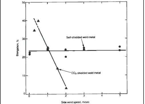
(8) externally supplied shielding gas is required, the process may be used in high winds without adversely affecting the quality of the deposit. With any of the gas shielded processes, wind shields must be erected to preclude interference with the gas shield in windy weather. Many fabricators have found self shielded flux core offers advantages for shop welding as well, since it permits the use of better ventilation.. mum specified notch toughness levels should be used. The corresponding Lincoln Electric products are also shown. Shielding gases for FCAW-g — Most of the gas shielded flux cored electrodes utilize carbon dioxide for the shielding media. However, electrodes may also be shielded with an argon-CO2 mixture. All gases should be of welding grade with a dew point of -40°F or less. The carbon dioxide content is typically 10% to 25%, with the balance composed of argon. This is done to enhance welding characteristics. In order to utilize the argon based shielding gases, arc voltages are typically reduced by two volts from the level used with carbon dioxide shielding.. Individual gas shielded flux cored electrodes tend to be more versatile than self shielded flux cored electrodes, and in general, provide better arc action. Operator appeal is usually higher. While the gas shield must be protected from winds and drafts, this is not particularly difficult in shop fabrication situations. Weld appearance and quality are very good. Higher strength gas shielded FCAW electrodes are available, while current technology limits self shielded FCAW deposits to 90 ksi tensile strength or less.. The selection of shielding gas may affect mechanical properties, including yield and tensile strength, elongation, and notch toughness. This is largely due to the difference in alloy recovery—that is, the amount of alloy transferred from the filler material to the weld deposit. Carbon dioxide is a reactive gas that may cause some of the alloys contained in the electrode (Mn, Si and others) to be oxidized, so that less alloy ends up in the deposit. When a portion of this active carbon dioxide is replaced with an inert gas such as argon, recovery typically increases, resulting in more alloy in the weld deposit. Generally, this will result in higher yield and tensile strengths, accompanied by a reduction in elongation. The notch toughness of the weld deposit may go up or down, depending on the particular alloy whose recovery is increased.. Filler metals for flux cored arc welding are specified in AWS A5.20 and A5.29. A5.20 covers mild steel electrodes, while A5.29 addresses low alloy materials. Positive polarity is always used for FCAW-g, although the self shielded electrodes may be used on either polarity, depending on their classification. Under A5.29 for alloy electrodes, a suffix letter followed by a number appears at the end. Common designations include “Ni1” indicating a nominal nickel content in the deposited metal of 1%. The letter “M” could appear at the end of the electrode classification. If this is done, the electrode has been designed for operation with mixed shielding gas, that is an argon-CO2 blend that consists of 75 - 80% argon. Other suffix designators may be used that indicate increased notch toughness capabilities, and/or diffusible hydrogen limits.. Storing FCAW electrodes — In general, FCAW electrodes will produce weld deposits which achieve hydrogen levels below 16 ml per 100 grams of deposited metal. These electrodes, like other products which produce deposits low in hydrogen, must be protected from exposure to the atmosphere in order to maintain hydrogen levels as low as possible, prevent rusting of the product and prevent porosity during welding. The recommended storage conditions are such that they maintain the condition of 90 grains of moisture per pound of dry air. Accordingly, the following storage conditions are recommended for FCAW electrodes in their original, unopened boxes and plastic bags.. Table 2.1 describes various FCAW electrodes listed in AWS A5.20 and A5.29. Some of the electrodes have minimum specified notch toughness values although others do not. Some are gas shielded, while others are self shielded. Some are restricted to single pass applications, and others have restrictions on the thickness for their application. The electrical polarity used for the various electrodes is also shown. For critical applications in buildings that are designed to resist seismic loading as determined by the Engineer of Record, only electrodes that are listed in Table 2.1 as having the required mini-. 4.
(9) Table 2.1 FCAW Electrode Classification. 5.
(10) Ambient Temperature Degrees F Degrees C 60 - 70 16 - 21 70 - 80 21 - 27 80 - 90 27 - 32 90 - 100 32 - 38. Some Innershield and Outershield products have been designed and manufactured to produce weld deposits meeting more stringent diffusible hydrogen requirements. These electrodes, usually distinguished by an “H” added to the product name, will remain relatively dry under recommended storage conditions in their original, unopened package or container.. Maximum % Relative Humidity 80 60 45 30. For critical applications in which the weld metal hydrogen must be controlled (usually H8 or lower), or where shipping and storage conditions are not controlled or known, only hermetically sealed packaging is recommended. Innershield and Outershield electrodes are available in hermetically sealed packages on a special order basis.. For best results, electrodes should be consumed as soon as practicable. However, they may be stored up to three years from the date of manufacture. The Lincoln distributor or sales representative should be consulted if there is a question as to when the electrodes were made. Once the electrode packaging is opened, Innershield and Outershield electrodes can be subject to contamination from atmospheric moisture. Care has been taken in the design of these products to select core ingredients that are essentially resistant to moisture pick-up; however, condensation of the moisture from the atmosphere onto the surface of the electrode can be sufficient to degrade the product.. Once the package has been opened, the electrode should not be exposed to conditions exceeding 80% relative humidity for a period greater than 16 hours, or any less humid condition for more than 24 hours. Conditions that exceed 80% RH will decrease the maximum 16 hour exposure period. After exposure, hydrogen levels can be reduced by conditioning the electrode. Electrodes may be conditioned at a temperature of 230ºF ± 25ºF for a period of 6 to 12 hours, cooled and then stored in sealed poly bags (4 mil minimum thickness) or equivalent. Electrodes on plastic spools should not be heated at temperatures in excess of 150ºF. Rusty electrodes should be discarded.. The following minimum precautions should be taken to safeguard product after opening the original package. Electrode should be used within approximately 1 week after opening the original package. Opened electrode should not be exposed to damp, moist conditions or extremes in temperature and/or humidity where surface condensation can occur. Electrodes mounted on wire feeders should be protected against condensation. It is recommended that electrode removed from its original packaging be placed in poly bags (4 mil minimum thickness) when not in use.. 2.3 SAW Submerged arc welding (SAW) differs from other arc welding processes in that a layer of fusible granular material called flux is used for shielding the arc and the molten metal. The arc is struck between the workpiece and a bare wire electrode, the tip of which is submerged in the flux. Since the arc is completely covered by the flux, it is not visible and the weld is made without the flash, spatter, and sparks that characterize the open-arc processes. The nature of the flux is such that very little smoke or visible fumes are released to the air.. In the case of FCAW-s, excessively damp electrodes can result in higher levels of spatter, poorer slag cover and porosity. FCAW-g electrodes will display high moisture levels in the form of gas tracks, higher spatter and porosity. Any rusty electrode should be discarded. Products used for applications requiring more restrictive hydrogen control — The AWS specification for flux cored electrodes, ANSI/AWS A5.20, states that “Flux cored arc welding is generally considered to be a low hydrogen welding process.” To further clarify the issue, this specification makes available optional supplemental designators for maximum diffusible hydrogen levels of 4, 8 and 16 ml per 100 grams of deposited weld metal.. Typically, the process is fully mechanized, although semiautomatic operation is often utilized. The electrode is fed mechanically to the welding gun, head, or heads. In semiautomatic welding, the welder moves the gun, usually equipped with a flux-feeding device, along the joint.. 6.
(11) High currents can be used in submerged arc welding and extremely high heat input levels can be developed. Because the current is applied to the electrode a short distance above its arc, relatively high amperages can be used on small diameter electrodes, resulting in extremely high current densities. This allows for high deposition rates and deep penetration.. electrodes in a multiple electrode configuration. AC welding currently is typically used for multi-electrode welding. If DC current is used, it usually is limited to the lead electrode to minimize the potentially negative interaction of magnetic fields between the two electrodes. Submerged arc filler materials are classified under AWS A5.17 for mild steel and AWS A5.23 for low alloy filler materials. Both fluxes and electrodes are covered under these specifications. Since submerged arc is a twocomponent process, that is, flux and electrode, the classification system is slightly different than for other filler materials.. Welds made under the protective layer of flux are excellent in appearance and spatter free. Since the process develops a minimum amount of smoke, the surrounding plate surfaces remain clear of smoke deposits. The high quality of submerged arc welds, the high deposition rates, the deep penetration characteristics, and the easy adaptability of the process to full mechanization make it popular for the manufacture of plate girders and fabricated columns.. Electrodes are classified based on the composition of the electrode. Under A5.17, the electrode will carry a classification that consists of two letters, one or two numerical digits and, in some cases, a final letter. The first letter is an E, which stands for electrode. The second letter will be L, M, or H, referring to a low, medium, or high level of manganese in the electrode. The next one or two digits refer to the nominal carbon content in hundredths of a percent. A “12” in this location, for example, would indicate a nominal carbon content of 0.12%. It should be emphasized that this is the nominal value; it is possible to have higher and lower carbon contents in a specific electrode. In some cases, the electrode will be made of killed steel. When this is the case, silicon normally is added and the electrode will have a “K” at the end of the classification (e.g., EM13K).. One of the greatest benefits of the SAW process is freedom from the open arc. This allows multiple arcs to be operated in a tight, confined area without the need for extensive shields to guard the operators from arc flash. Yet this advantage also proves to be one of the chief drawbacks of the process; it does not allow the operator to observe the weld puddle. When SAW is applied semiautomatically, the operator must learn to propel the gun carefully in a fashion that will ensure uniform bead contour. The experienced operator relies on the uniform formation of a slag blanket to indicate the nature of the deposit. For single pass welds, this is mastered fairly readily; however, for multiple pass welding, the degree of skill required is significant. Therefore, most submerged arc applications are mechanized. The nature of the joint must then lend itself to automation if the process is to prove viable. Long, uninterrupted straight seams are ideal applications for submerged arc. Short, intermittent welds are better made with one of the open arc processes.. Electrodes classified under A5.23, the low alloy variety, have a more complex nomenclature, because of the variety of alloys that may be involved. The most important alloys for structural welding are the “Ni,” or nickel alloys, and “W,” or weathering alloys (e.g., ENi1K). Fluxes are always classified in conjunction with an electrode. The flux-electrode combination must meet specific mechanical property requirements. After a flux is selected and a classification test plate welded, a fluxelectrode classification may be established. Specimens are extracted from the weld deposit to obtain the mechanical properties of the flux-electrode combination. The classification will follow the format of an “F” followed by a single or two digit number, an “A” or “P,” a single digit and a hyphen which separates the electrode classification. Thus, a typical flux-electrode may be classified as an F7A2-EM12K. The “F” stands for flux, and the “7” indicates all of the following: a 70-95 ksi tensile strength deposit, a 58 ksi minimum yield strength, and a. Two electrodes may be fed through a single electrical contact tip, resulting in higher deposition rates. Generally known as parallel electrode welding, the Lincoln trade name for this is Tiny Twin® or Twin Arc®. The equipment is essentially the same as that used for single electrode welding, and parallel electrode welding procedures may be prequalified under AWS D1.1-96. Multiple electrode SAW refers to a variation of submerged arc which utilizes at least two separate power supplies, two separate wire drives, and feeds two electrodes independently. Some applications such as the manufacture of line pipe may use up to five independent 7.
(12) minimum of 22% elongation. The “A” indicates the deposit is tested in the as-welded condition. The “2” indicates 20 ft. lbf. at -20°F, and the balance of the classification identifies the electrode used.. Larger pieces of fused slag should be separated from the recovered flux in order to avoid flux feeding problems. The automated systems typically have screening to handle this. The fused slag may be chemically different than the unfused flux. For less critical applications, this slag may be crushed and thoroughly intermixed with new flux. This is sometimes called “recycled flux,” but since reclaimed flux is sometimes referred to by the same term, a better description for this product is “crushed slag.” Performance and mechanical properties of crushed slag may differ from those of virgin flux. AWS D1.1-96 requires that crushed slag must be classified in much the same way as new flux. (See AWS D1.1-96, paragraph 5.3.3.4). Because of the popularity of the submerged arc process for pressure vessel fabrication where assemblies are routinely stress relieved, submerged arc products may be classified in the post weld heat treated, or stress relieved, condition. When this is done, a “P” replaces the “A.” For structural work, which is seldom stress relieved, the “A” classification is more common. For products classified under A5.23, a format similar to that of A5.17 is used, with this major exception: at the end of the flux-electrode classification, a weld deposit composition is specified. For example, an F7A2-ENi1Ni1 would indicate that the electrode, an ENi1, delivers an F7A2 deposit when used with a specific flux. In addition, the deposit has a composition that meets the requirements of an Ni1. In this case, a nickel bearing electrode deposits a weld that contains nickel. The example is straightforward. However, it is also possible to use alloy fluxes which, with mild steel electrodes, are capable of delivering alloy weld metal. In this case, a typical classification may be an F7A2-EL12-Nil. In this example, an EL12 electrode (a non-alloy electrode that contains a low level of manganese) is used with an alloy flux. The result is an alloyed deposit. This is commonly done when nickel bearing deposits are desired on weathering steel that will not be painted.. Flux must be stored so that it remains dry. The manufacturer’s guidelines regarding storage and usage of the flux must be followed. In use, granules of flux must not come in direct contact with water since weld cracking can result. Fluxes can be contaminated with moisture from the atmosphere, so exposure should be limited. When not in use, flux hoppers should be covered or otherwise protected from the atmosphere. Lincoln Electric’s recommendations for storage and handling of flux are outlined in Literature # C5.660. 2.4 GMAW Gas metal arc welding (GMAW) utilizes equipment much like that used in flux cored arc welding. Indeed, the two processes are very similar. The major differences are: gas metal arc uses a solid or metal cored electrode, and leaves no appreciable amount of residual slag. Gas metal arc has not been a popular method of welding in the typical structural steel fabrication shop because of its sensitivity to mill scale, rust, limited puddle control, and sensitivity to shielding loss. Newer GMAW metal cored electrodes, however, are beginning to be used in the shop fabrication of structural elements with good success.. Only part of the flux deposited from a hopper or a gun is fused in welding. The unfused, granular flux may be recovered for future use and is known as reclaimed flux. The unmelted flux does not undergo chemical changes and may therefore be capable of delivering quality welds when used the next time. However, this flux can be contaminated in the act of recovery. If it comes in contact with oil, moisture, dirt, scale or other contaminants, the properties of the weld deposit made with reclaimed flux may be adversely affected. Care should be exercised to ensure that flux is not thus contaminated. Another problem with reclaimed flux is the potential for the breakdown of particles and the modification of the particle size distribution. This can affect the quality and/or properties. The method of flux recovery can range from sweeping up the flux with broom and pans, to vacuum recovery systems; the method chosen should take into account the need to avoid contamination.. A variety of shielding gases or gas mixtures may be used for GMAW. Carbon dioxide (CO2) is the lowest cost gas, and while acceptable for welding carbon steel, the gas is not inert but active at elevated temperatures. This has given rise to the term MAG (metal active gas) for the process when (CO2) is used, and MIG (metal inert gas) when predominantly argon-based mixtures are used. While shielding gas is used to displace atmospheric oxygen, it is possible to add smaller quantities of oxygen into. 8.
(13) mixtures of argon — generally at levels of 2 - 8%. This helps stabilize the arc and decreases puddle surface tension, resulting in improved wetting. Tri- and quadmixes of argon, oxygen, carbon dioxide and helium are possible, offering advantages that positively affect arc action, deposition appearance and fume generation rates.. Spray arc transfer is characterized by high wire feed speeds at relatively high voltages. A fine spray of molten drops, all smaller in diameter than the electrode diameter, is ejected from the electrode toward the work. Unlike short arc transfer, the arc in spray transfer is continuously maintained. High quality welds with particularly good appearance are the result. The shielding used for spray arc transfer is composed of at least 80% argon, with the balance made up of either carbon dioxide or oxygen. Typical mixtures would include 90-10 argon-CO2, and 95-5 argon-oxygen. Other proprietary mixtures are available from gas suppliers. Relatively high arc voltages are used with the spray mode of transfer. However, due to the intensity of the arc, spray arc is restricted to applications in the flat and horizontal position, because of the puddle fluidity, and lack of a slag to hold the molten metal in place.. Short arc transfer is ideal for welding on thin gauge materials. It is generally not suitable for structural steel fabrication purposes. In this mode of transfer, the small diameter electrode, typically 0.035 in. or 0.045 in., is fed at a moderate wire feed speed at relatively low voltages. The electrode will touch the workpiece, resulting in a short in the electrical circuit. The arc will actually go out at this point, and very high currents will flow through the electrode, causing it to heat and melt. Just as excessive current flowing through a fuse causes it to blow, so the shorted electrode will separate from the work, initiating a momentary arc. A small amount of metal will be transferred to the work at this time.. Pulsed arc transfer utilizes a background current that is continuously applied to the electrode. A pulsing peak current is optimally applied as a function of the wire feed speed. With this mode of transfer, the power supply delivers a pulse of current which, ideally, ejects a single droplet of metal from the electrode. The power supply returns to a lower background current which maintains the arc. This occurs between 100 and 400 times per second. One advantage of pulsed arc transfer is that it can be used out-of-position. For flat and horizontal work, it may not be as fast as spray transfer. However, used outof- position, it is free of the problems associated with gas metal arc short circuiting mode. Weld appearance is good and quality can be excellent. The disadvantage of pulsed arc transfer is that the equipment is slightly more complex and more costly. The joints are still required to be relatively clean, and out-of-position welding is still more difficult than with processes that generate a slag that can support the molten puddle.. The cycle will repeat itself again once the electrode shorts to the work. This occurs somewhere between 60 and 200 times per second, creating a characteristic buzz to the arc. This mode of transfer is ideal for sheet metal, but results in significant fusion problems if applied to heavy materials. A phenomenon known as cold lap or cold casting may result where the metal does not fuse to the base material. This is unacceptable since the welded connections will have virtually no strength. Great caution must be exercised in the application of the short arc mode to heavy plates. The use of short arc on heavy plates is not totally prohibited however, since it is the only mode of transfer that can be used out-of-position with gas metal arc welding, unless specialized equipment is used. Weld joint details must be carefully designed when short arc transfer is used. Welders must pass specific qualification tests before using this mode of transfer. The mode of transfer is often abbreviated as GMAW-s, and is not prequalified by the D1.1 code.. Metal cored electrodes are a relatively new development in gas metal arc welding. This is similar to flux cored arc welding in that the electrode is tubular, but the core material does not contain slag forming ingredients. Rather, a variety of metallic powders is contained in the core. The resulting weld is virtually slag-free, just as with other forms of GMAW. The use of metal cored electrodes offers many fabrication advantages. They have increased ability to handle mill scale and other surface contaminants. Finally, metal cored electrodes permit the use of high amperages that may not be practical with solid electrodes, resulting in potentially higher deposition rates. The properties obtained from metal. Globular transfer is a mode of gas metal arc welding that results when high concentrations of carbon dioxide are used, resulting in an arc that is rough with larger globs of metal ejected from the end of the electrode. This mode of transfer, while resulting in deep penetration, generates relatively high levels of spatter. Weld appearance can be poor and it is restricted to the flat and horizontal position. Globular transfer may be preferred over spray transfer because of the low cost of CO2 shielding gas and the lower level of heat experienced by the operator. 9.
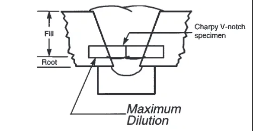
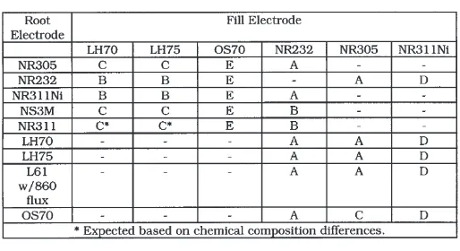
(14) cored deposits can be excellent. Appearance is very good. Because of the ability of the filler metal manufacturer to control the composition of the core ingredients, mechanical properties obtained from metal cored deposits may be more consistent than those obtained with solid electrodes. However, metal cored electrodes are in general more expensive.. Another common application is for the welding of continuity plates inside box columns. It is possible to weld three sides of the continuity plate to the interior of the box prior to closing the box with the fourth side. However, once this closure is made, access to the final side of the continuity plate is restricted. It is possible to use these processes to make this final closure weld by operating through a hole in the outside of the box column. This approach is very popular in Asia, where box columns are widely used.. 2.5 ESW/EGW Electroslag and electrogas welding (ESW/EGW) are closely related processes that offer high deposition welding in the vertical plane. Properly applied, these processes offer significant savings over alternative out-of-position methods and in many cases, a savings over flat position welding. Although the two processes have similar applications and mechanical set up, there are fundamental differences in the arc characteristics.. In electroslag welding, a granular flux is metered into the joint during the welding operation. At the beginning, an arc, similar to that of submerged arc welding, is established between the electrode and the sump. After the initial flux is melted into a molten slag, the reaction changes. The slag, which is carefully designed to be electrically conductive, will conduct the welding current from the electrode through the slag into the pieces of steel to be joined. As high currents are passed through the slag, it becomes very hot. The electrode is fed through the hot slag and melts. Technically, electroslag welding is not an arc welding process, but a resistance welding process. Once the arc is extinguished and the resistance melting process is stabilized, the weld continues vertically to completion. A small amount of slag is consumed as it chills against the water cooled copper shoes. In some cases, steel dams instead of copper dams are used to retain the puddle. After completion of the weld, the steel dams stay in place, and become part of the final product. Slag must be replenished, and additional flux is continuously added to compensate for the loss.. Electroslag and electrogas are mechanically similar in that both utilize copper dams or shoes that are applied to either side of a square edged butt joint. An electrode or multiple electrodes are fed into the joint. A starting sump is typically applied for the beginning of the weld. As the electrode is fed into the joint, a puddle is established that progresses vertically. The copper dams, which are commonly water cooled, chill the weld metal and prevent it from escaping from the joint. The weld is completed in one pass. These processes may be used for groove welds in butt, corner and tee joints. Typical applications involve heavier plate, usually 1” or thicker. Multiple electrodes may be used in a single joint, allowing very heavy plate up to several inches thick to be joined in a single pass. Because of the sensitivity of the process to the variety of variables involved, specific operator training is required, and the D1.1-96 code requires welding procedures to be qualified by test.. One aspect of electroslag welding that must be considered is the very high heat input associated with the process. This causes a large heat affected zone (HAZ) that may have a lower notch toughness. Electrogas welding is different from electroslag, inasmuch as no flux is used. Electrogas welding is a true arc welding process and is conceptually more like gas metal arc or flux cored arc welding. A solid or tubular electrode is fed into the joint, which is flooded with an inert gas shield. The arc progresses vertically while the puddle is retained by the water cooled dams.. In building construction, applications for ESW/EGW with traditional connection designs are somewhat limited. However, they can be highly efficient in the manufacture of tree columns. In the shop, the beam flange-to-column welds can be made with the column in the horizontal plane. With the proper equipment and tooling, all four flange welds can be made simultaneously. In addition, continuity plate welds can be made with ESW/EGW. Future connection designs may utilize configurations that are more conducive to these processes.. The Lincoln Vertishield® system uses a self shielded flux cored electrode, and while no gas is required, it is classified as EGW since it is an open arc process.. 10.
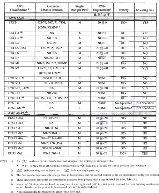
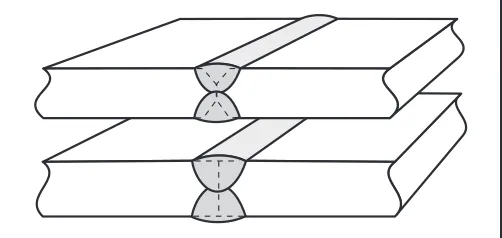
(15) The HAZ performance is dependent not only on the heat input, but also on the nature of the steel. While all processes develop a heat affected zone, the large size of the electroslag heat affected zone justifies additional scrutiny. Advances in steel technology have resulted in improved steels, featuring higher cleanliness and toughness, that better retain the HAZ properties in ESW/EGW welds. 3. Welding Process Selection. Figure 3-1 Joints requiring substantial fill. Any of the common arc welding processes can be used to achieve the quality required for structural steel applications. While each may have a particular area of strength and/or weakness, the primary consideration as to which process will be used is largely driven by cost. The availability of specialized equipment in one fabrication shop, compared to the capabilities of a second shop, may dictate significantly different approaches, both of which may prove to be cost effective. A history of successful usage offers a strong incentive for the fabricator to continue using a given process. The reasons for this go well beyond familiarity and comfort with a specific approach. When welders and procedures are established with a given process, significant costs will be incurred with any change to a new approach.. feet of weld that can be made in a given hour assuming 100% arc time. This, of course, translates directly to productivity rates. The second criterion imposed by weld joints is the requirement for penetration. Examples are listed under Fig. 3-2 and would include any complete joint penetration groove weld that has a root face dimension. These joints will be made by welding from one side and back gouging from the second to ensure complete fusion. With deeper penetration afforded by the welding process, a smaller amount of base metal will be required to be removed by back gouging. Subsequent welding will then be proportionately reduced as well.. 3.1 Joint Requirements Each individual weld joint configuration and preparation has certain requirements of the welding process in order to achieve low cost welding. Four characteristics must be considered: deposition rate, penetration ability, outof-position capability, and high travel speed capacity. Each process exhibits different capabilities in these realms. Once the joint and its associated requirements are analyzed, they should be compared to the various process options and the ability of the process to achieve those requirements. A proper match of weld joint requirements and process capabilities will lead to dependable and economical fabrication.. Figure 3-2 Joints requiring substantial penetration While all welding requires fusion, not all joints require deep penetration. For example, simple fillet welds are required by AWS D1.1-96 to have fusion to the root of the joint, but are not required to have penetration beyond the root. This has a practical basis: verification of penetration beyond the root is impossible with visual inspection. Fusion to the root, and not necessarily beyond, ensures that sufficient strength is generated, provided the weld is properly sized. While penetration can be verified with ultrasonic inspection, fillet welds routinely receive only visual or magnetic particle inspection. Thus, no penetra-. Some welds, such as large fillet welds and groove welds require that high deposition rate welding be used (Fig. 3-1) for the most economical fabrication. The cost of making these welds will be determined largely by the deposition rate of the process. The amount of weld material required may be measured in pounds per foot of joint. Once the deposition rate of a process in pounds per hour is known, it is possible to determine the number of. 11.
(16) tion beyond the root is required, nor is design credit given to deeper penetration in fillet welds if it happens to be present. Figure 3-3 illustrates this requirement.. Deep penetration is offered by the submerged arc welding process. While electroslag/electrogas also offers deep penetration, the joints on which electroslag are used typically do not require this capability. Where open arc processes are preferred, gas shielded flux cored welding may offer deep penetration.. The out-of-position capability of a given welding process refers to the ability to deposit weld metal in the vertical or overhead positions. It is generally more economical to position the work in the flat and horizontal positions. However, this is usually impossible for field erection, and may be impractical under other conditions.. Out-of-position capability is strongest for the flux cored and shielded metal arc welding processes. The slag coatings that are generated by these processes can be instrumental in retaining molten weld metal in the vertical and overhead positions. Submerged arc is not applicable for these joints.. The ability to obtain high travel speeds is important for small welds. It may not be possible for a high deposition welding process to be used at high travel speeds. The size of the droplet transferred, puddle fluidity, surface tension, and other factors combine to make some processes more capable of high travel speeds than others.. The requirement for high travel speed capability is fairly limited in terms of welding structural steel members. This typically consists of the travel speed associated with making a 1/4 in. fillet weld. All of the popular processes, with the exception of electroslag/electrogas, are capable of making 1/4 in. fillet welds under the proper conditions. Among the variables that need to be considered are electrode size and procedure variables. A common mistake of fabricators is to utilize a process and procedure capable of extremely high deposition rates, but limited travel speeds. Oversized welds can result from the inability to achieve high travel speeds. A more economical approach would be to optimize the procedure according to the desired travel speed. This may result in a lower deposition rate but a lower overall cost because overwelding has been eliminated.. 3.2 Process Capabilities After the joint is analyzed and specific requirements determined, these are compared to the capabilities of various processes. The process with capabilities most closely matching the requirements typically will be the best and most economical option. Submerged arc welding and electroslag/electrogas welding have the greatest potential to deliver high deposition rates. Multiple electrode applications of submerged arc extend this capability even further. For joints requiring high deposition rates, submerged arc and electroslag/electrogas welding are ideal processes to contribute to low cost welding. When the specific conditions are not conducive to SAW but high deposition rates are still required, flux cored arc welding may be used. The larger diameter electrodes, which run at higher electrical currents, are preferred.. 3.3 Special Situations Self shielded flux cored welding is ideal for outdoor conditions. Quality deposits may be obtained without the erection of special wind shields and protection from drafts. Shielded metal arc welding is also suitable for these conditions, but is considerably slower.. Figure 3-3 Fillet weld requirements 12.
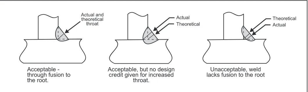
(17) 3-4 illustrates the effect of shielding gas loss on weld deposits, as well as the resistance to this problem with the FCAW-ss process. The code specifically limits wind velocity in the vicinity of a weld to a maximum of 5 miles per hour (2.3 m/s) (D1.1-96, paragraph 5.12.1). In order to utilize gas shielded processes under these conditions, it is necessary to erect windshields to preclude movement of the shielding gas with respect to the molten weld puddle. While tents and other housings can be created to minimize this problem, such activities can be costly and are often a fire hazard. In addition, adequate ventilation must be provided for the welder. The most efficient windshields may preclude adequate ventilation. Under conditions of severe shielding loss, weld porosity will be exhibited. At much lower levels of shielding loss, the mechanical properties (e.g., notch toughness and ductility) may be negatively affected, although there will be no obvious evidence that this is taking place.. Figure 3-4a Comparison of the effect of side wind on tensile elongation of: (a) CO2-shielded and (b) self shielded ferritic steel weld metals. (source: Self-Shielded Arc Welding. T. Boniszewski, 1992.). A variety of other gas-related issues are also eliminated, including ensuring availability of gas, handling of high pressure cylinders (always a safety concern), theft of cylinders, protection of gas distribution hosing under field conditions, and the cost of shielding gas. Leaks in the delivery system obviously waste shielding gas, but a leak can also allow entry of air into the delivery system. Weld quality can be affected in the same way as shielding loss. Most field erectors have found it advantageous to utilize the self-shielded process and circumvent all such potential problems. Some projects permit multiple welding heads to be simultaneously operated in the same general vicinity. For such applications, submerged arc is an ideal choice. Because of the lack of arc flash, one operator can control multiple arcs that are nearly impossible to control in a situation where the arc intensity from one arc would make it difficult to carefully control another. A typical example would be the use of welding systems that simultaneously make fillet welds on opposing sides of stiffeners.. Figure 3-4b Comparison of the effect of side wind speed on Charpy V-notch impact toughness of: (a) CO2 -shielded at room temperature and (b) self shielded ferritic steel weld metals at 0°C. (source: Self-Shielded Arc Welding. T. Boniszewski, 1992.). The welding process of choice for field erectors for the last 25 years has been FCAW-ss. It has been the commonly used process for fabrication of steel structures throughout the United States. Its advantages are reviewed in order to provide an understanding of why it has been the preferred process. In addition, its limitations are outlined to highlight areas of potential concern.. The easiest way to control smoke and fumes in the welding environment is to limit their initial generation. Here, submerged arc is ideal. Smoke exhaust guns are available for the flux cored arc welding processes. The most effective process for use with these smoke exhaust guns is FCAW-ss. Because the process is self shielded, there is no concern about the disruption of the gas shielding. See 11 on arc welding safety.. The chief advantage of the FCAW-ss process is its ability to deposit quality weld metal under field conditions, which usually involve wind. The graph shown in Figure. 13.
(18) 4. Welding Cost Analysis. the work or the welder with respect to the work, etc. To account for this time, an “operating factor” is used which is defined as the “arc-on” time divided by the total time associated with welding activities. For SMAW, replacement of electrodes takes place approximately every minute because of the finite length of the electrodes used. The following operating factors are typically used for the various processes and method of application: Operating factors for any given process can vary widely,. Welding is a labor intensive technology. Electricity, equipment depreciation, electrodes, gases, and fluxes constitute a very small portion of the total welding cost. Therefore, the prime focus of cost control will be reducing the amount of time required to make a weld. The following example is given to illustrate the relative costs of material and labor, as well as to assess the effects of proper process selection. The example to be considered is the groove weld of beam flange to column connections. Since this is a multiple pass weld, the most appropriate analysis method is to consider the welding cost per weight of weld metal deposited, such as $/lb. Other analysis methods include cost per piece, ideal for manufacturers associated with the production of identical parts on a repetitive basis. Another method is cost per length, appropriate for single pass welds with substantial length. The two welding processes to be considered are shielded metal arc welding and flux cored arc welding. Either would generate high quality welds when properly used.. Method Manual SMAW Semiautomatic Mechanized. depending on what a welder is required to do. In shop situations, a welder may receive tacked assemblies and be required only to weld and clean them. For field erection, the welder may “hang iron,” fit, tack, bolt, clean the joint, reposition scaffolding and other activities in addition to welding. Obviously operating factors will be significantly reduced under these conditions. The following examples are the actual procedures used by a field erector. The labor and overhead cost does not necessarily represent actual practice. The operating factors are unrealistically high for a field erection site, but have been used to enable comparison of the relative cost of filler metals vs. the labor required to deposit the weld metal, as well as the difference in cost for different processes. Once the cost per deposited pound is known, it is relatively simple to determine the quantity of weld metal required for a given project, and multiply it by the cost per weight to determine the cost of welding on the project.. To calculate the cost per weight of weld metal deposited, an equation taking the following format is used: Cost per = weight. Electrode Cost Efficiency. +. Labor + Overhead Rate (Deposition Rate) (Operating Factor). The cost of the electrode is simply the purchase cost of the welding consumable used. Not all of this filler metal is converted directly to deposited weld metal. There are losses associated with slag, spatter, and in the case of SMAW, the stub loss (the end portion of the electrode that is discarded). To account for these differences, an efficiency factor is applied. The following efficiency factors are typically used for the various welding processes: Process SMAW FCAW GMAW SAW. Operating Factor 30% 40% 50%. Process SMAW Electrode Classification E7018 Electrode Diameter 3/16” Amperage 225 Voltage N.A. Electrode Efficiency 60% Electrode Cost $1.23/lb. Operating Factor 30% Deposition Rate 5.5 lb./hr. Labor and Overhead Rate $50/hr. Efficiency 60% 80% 90% (CO2 shielding) 98% (Mixed gas) 100% (Flux not included). The cost to deposit the weld metal is determined by dividing the applicable labor and overhead rate by the deposition rate, that is, the amount of weld metal deposited in a theoretical, continuous one hour of production. This cannot be maintained under actual conditions since welding will be interrupted by many factors, including slag removal, replacement of electrode, repositioning of. FCAW E70TG-K2 7/64” 430 27 80% $2.27/lb. 40% 14.5 lb./hr. $50/hr.. For SMAW: Cost per = weight. $1.23 $50.00 = $2.05 + $30.30 = $32.35/lb. + 60% (5.5) (30%). For FCAW: Cost per = weight. 14. $2.27 $50.00 = $2.84 + $8.62 = $11.46/lb. + 80% (14.5) (40%).
(19) In the SMAW example, the electrode cost is approximately 6% of the total cost. For the FCAW example, primarily due to a decrease in the labor content, the electrode cost is 25% of the total. By using FCAW, the total cost of welding was decreased approximately 65%. While the FCAW electrode costs 85% more than the SMAW electrode, the higher electrode efficiency reduces the increase in electrode cost to only 39%.. 5.1 Effects of Welding Variables The effects of the variables are somewhat dependent on the welding process being employed, but general trends apply to all the processes. It is important to distinguish the difference between constant current (CC) and constant voltage (CV) electrical welding systems. Shielded metal arc welding is always done with a CC system. Flux cored welding and gas metal arc welding generally are performed with CV systems. Submerged arc may utilize either.. The first priority that must be maintained when selecting welding processes and procedures is the achievement of the required weld quality. For different welding methods which deliver the required quality, it is generally advantageous to utilize the method that results in higher deposition rates and higher operating factors. This will result in reduced welding time with a corresponding decrease in the total building erection cycle, which will generally translate to a direct savings for the final owner, not only lowering the cost of direct labor, but also reducing construction loan costs. 5. Amperage is a measure of the amount of current flowing through the electrode and the work. It is a primary variable in determining heat input. Generally, an increase in amperage means higher deposition rates, deeper penetration, and more admixture. The amperage flowing through an electrical circuit is the same, regardless of where it is measured. It may be measured with a tong meter or with the use of an electrical shunt. The role of amperage is best understood in the context of heat input and current density considerations. For CV welding, an increase in wire feed speed will directly increase amperage. For SMAW on CC systems, the machine setting determines the basic amperage, although changes in the arc length (controlled by the welder) will further change amperage. Longer arc lengths reduce amperage.. Welding Procedures. Within the welding industry, the term “Welding Procedure Specification” (or WPS) is used to signify the combination of variables that are to be used to make a certain weld. The terms “Welding Procedure,” or simply “Procedure,” may be used. At a minimum, the WPS consists of the following:. Arc voltage is directly related to arc length. As the voltage increases, the arc length increases, as does the demand for arc shielding. For CV welding, the voltage is determined primarily by the machine setting, so the arc length is relatively fixed in CV welding. For SMAW on CC systems, the arc voltage is determined by the arc length, which is manipulated by the welder. As arc lengths are increased with SMAW, the arc voltage will increase, and the amperage will decrease. Arc voltage also controls the width of the weld bead, with higher voltages generating wider beads. Arc voltage has a direct effect on the heat input computation.. WPS Variables Process (SMAW, FCAW, etc.) Electrode specification (AWS A5.1, A5.20, etc.) Electrode classification (E7018, E71T-1, etc.) Electrode diameter (1/8 in., 5/32 in., etc.) Electrical characteristics (AC, DC+, DC-) Base metal specification (A36, A572 Gr50, etc.) Minimum preheat and interpass temperature Welding current (amperage)/wire feed speed Arc voltage Travel speed Position of welding Post weld heat treatment Shielding gas type and flow rate Joint design details. The voltage in a welding circuit is not constant, but is composed of a series of voltage drops. Consider the following example: assume the power source delivers a total system voltage of 40 volts. Between the power source and the welding head or gun, there is a voltage drop of perhaps 3 volts associated with the input cable resistance. From the point of attachment of the work lead to the power source work terminal, there is an additional voltage drop of, say, 7 volts. Subtracting the 3 volts and the. The welding procedure is somewhat analogous to a cook’s recipe. It outlines the steps required to make a weld of the required quality under specific conditions. 15.
(20) 7 volts from the original 40, this leaves 30 volts for the arc. This example illustrates how important it is to ensure that the voltages used for monitoring welding procedures properly recognize any losses in the welding circuit. The most accurate way to determine arc voltage is to measure the voltage drop between the contact tip and the work piece. This may not be practical for semiautomatic welding, so voltage is typically read from a point on the wire feeder (where the gun and cable connection is made), to the workpiece. For SMAW welding, voltage is not usually monitored, since it is constantly changing and cannot be controlled except by the welder. Skilled welders hold short arc lengths to deliver the best weld quality.. ing on the polarity, electrode diameter, electrode type, and electrode extension. Although equipment has been available for twenty years that monitors wire feed speed, many codes such as AWS D1.1 continue to acknowledge amperage as the primary method for procedure documentation. D1.1 does permit the use of wire feed speed control instead of amperage, providing a wire feed speed amperage relationship chart is available for comparison. Specification sheets for various Lincoln electrodes provide data that report these relationships. Electrode extension, also known as “stickout,” or ESO, is the distance from the contact tip to the end of the electrode. It applies only to the wire fed processes. As the electrode extension is increased in a constant voltage system, the electrical resistance of the electrode increases, causing the electrode to be heated. This is known as resistance heating or “I2R heating.” As the amount of heating increases, the arc energy required to melt the electrode decreases. Longer electrode extensions may be employed to gain higher deposition rates at a given amperage. When the electrode extension is increased without any change in wire feed speed, the amperage will decrease. This results in less penetration and less admixture. With the increase in electrode stickout, it is common to increase the machine voltage setting to compensate for the greater voltage drop across the electrode.. Travel speed, measured in inches per minute, is the rate at which the electrode is moved relative to the joint. All other variables being equal, travel speed has an inverse effect on the size of the weld beads. As the travel speed increases, the weld size will decrease. Extremely low travel speeds may result in reduced penetration, as the arc impinges on a thick layer of molten metal and the weld puddle rolls ahead of the arc. Travel speed is a key variable used in computing heat input; reducing travel speed increases heat input. Wire feed speed is a measure of the rate at which the electrode is passed through the welding gun and delivered to the arc. Typically measured in inches per minute (ipm) the wire feed speed is directly proportional to deposition rate, and directly related to amperage. When all other welding conditions are maintained constant (e.g., the same electrode type, diameter, electrode extension, arc voltage, and electrode extension), an increase in wire feed speed will directly lead to an increase in amperage. For slower wire feed speeds, the ratio of wire feed speed to amperage is relatively constant and linear.. In constant voltage systems, it is possible to simultaneously increase the electrode stickout and wire feed speed in a balanced manner so that the current remains constant. When this is done, higher deposition rates are attained. Other welding variables such as voltage and travel speed must be adjusted to maintain a stable arc and to ensure quality welding. The ESO variable should always be within the range recommended by the manufacturer.. For higher levels of wire feed speed, it is possible to increase the wire feed speed at a disproportionately high rate compared to the increase in amperage. When these conditions exist, the deposition rate per amp increases, but at the expense of penetration.. Electrode diameter — Larger electrodes can carry higher welding currents. For a fixed amperage, however, smaller electrodes result in higher deposition rates. This is because of the effect on current density discussed below.. Wire feed speed is the preferred method of maintaining welding procedures for constant voltage wire feed processes. The wire feed speed can be independently adjusted, and measured directly, regardless of the other welding conditions. It is possible to utilize amperage as an alternative to wire feed speed although the resultant amperage for a given wire feed speed may vary, depend-. Polarity is a definition of the direction of current flow. Positive polarity (reverse) is achieved when the electrode lead is connected to the positive terminal of the direct current (DC) power supply. The work lead is connected to the negative terminal. Negative polarity (straight) occurs when the electrode is connected to the negative 16.
Figure
+7
Related documents