Solid State Transformers: The State-of-the-Art,
Challenges and Applications
Mahmoud Mazhar Samad
Abstract— The solid state transformer SST is a new technology that will lead to the replacement of the 8,000-pound transformer with a small board circuit and thus shrink it down to look more like a suite case. This property allows the SST to gain even more importance and attention from different institutions and industries through using it for different applications. This paper presents a review on the smart SST. This review includes the different developments achieved from this asset and addresses the technology from different point of views, topologies, efficiencies and high voltage SST. The paper then summarizes the SST’s application in the grid and the challenges it sets out after using this new asset into the system. It has been concluded that the SST will play a key role in the new required smart grid.
Keywords— High frequency transformer; Power semiconductor devices; Solid state transformer (SST); Smart Grid.
I. INTRODUCTION
Since the beginning of the second millennium, the renewable energy resources have been getting more attention and the growing use of these renewable energy resources as a major source in the grid reduces the emission of greenhouse gases. It is a plan to protect Earth from the climate changes, but different challenges appear and several problems should be solved to achieve the goal of increasing the using of renewable energy and getting the required criteria out of the smart grid. The International Renewable Energy Agency (IRENA) set the most important points require developments to achieve the required uses of Renewable resources: increase energy storage capacity, enabling bi-directional energy flow, improve grid interconnection and adopt enhancing technology [1]. One of the most important assets in the power system is the transformer, where the transformer is used in the generation station to step up the voltage for better transmitting with lower power loss. It is then used to step down the voltage several times in the distribution grids until it reaches the consumers. Many researches are going on this asset to replace it from the huge magnetic transformer to smart Solid State Transformer SST. SST is a kind of transformer which can control input and output power with controlling the voltage level using a numbers of switched electronic devices. SST has different advantages compared to the classical magnetic one. The SST can reduce the size of the transformer to a lighter weight where the frequency could be raised hundred to thousand times than the used frequency (50/60Hz). This is proved from the transformer EMF equation Ea = 4.44 x f x Bm x Acm x Na [2.6]. In addition, it is able to perform additional functions with the help of semiconductor devices like: controlling output voltage, compensating reactive power, having fast voltage regulation, under voltage ride-through capability, and achieve power
Manuscript received February 19, 2019; revised March 07, 2019. S.M. Mahmoud, is a Student in Glasgow Caledonian University, U.K. with a Master course in Electrical Power Engineering ([email protected]).
factor correction [3]. Different researches have already started to add advanced functions to SST like the Unified power quality conditioner (UPQC), where its purpose is to compensate for imbalanced voltage, negative-sequence current, reactive power and harmonics [4], or using it as an active filter [5]. Generally, the basic idea of the SST is to transform voltages in medium and high frequency isolation which will directly reduce the size and weight of this asset compared to the classical one. The main focuses are on the high-voltage high-frequency operated power electronic devices, high-frequency high-power SST, with higher efficiency. This paper contains five different sections, after this small introduction to the topic, an explanation is written on the state-of-art for the SST regarding its topologies, High power voltage devices and its efficiency, third section is for the application of SST in different major like distribution system, renewable sources and traction systems after that, an overview is made about the challenges appeared in using the SST which summarized in the availability of the power semiconductor, magnetic material and heat management, reliability and efficiency, last part has a brief conclusion of this paper.
II. STATE-OF-THE-ART.
A. Topologies of Solid State Transformer
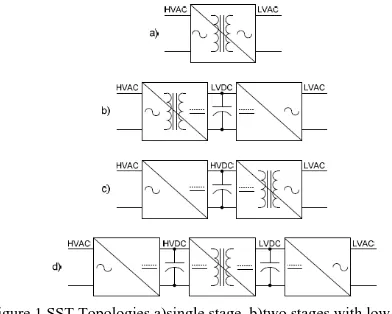
[image:1.595.318.514.533.690.2]Different topologies have been studied to check the ability of each type used and compare the pros and cons between them for improving the performance of the SST and to choose the best topology depends on the function required. The possible topologies can be classified as single stage, two stages and three stages SST as shown in Figure 1 [7].
Figure 1 SST Topologies a)single stage, b)two stages with low voltage, c)two stage with high voltage and d)three stages
current [9,10] but here the number of switches are doubled to build the four quadrant. The single stage SST as it is known the simplest circuit compare to two and three stages and regarding the comparison made in [7] the single stage has the lower switching frequency which means the lower switching losses but also it shows limited functionalities. The two stages SST topology is based on the AC-DC version where the DC link is used here, the AC-DC version could have an isolated Boost converter with PWM inverter or Dual Active Bridge DAB with PWM inverter and in both methods the DC link will be in low voltage LVDC link. The first version of isolated Boost converter should have a modulated PWM voltage at the input terminal to obtain sinusoidal input current, this version has a cons of using two different controls strategy depending on the power flow direction. The second version of DAB [11], has phase shift angle modulated to obtain sinusoidal input current, cons of this version is based on the high sensitivity and the large ripple current. From the comparison made in [7] the switching losses has no difference between two and three stages SST where the three stages could offer an additional functionalities compared to two stages. A two stages SST can also use High voltage DC link HVDC [12], if Cycloconverter is used for AC-AC conversion with high frequency transformer.
The three stages SST is the most interesting type where it can offer all required functionalities for replacing the classical transformer [13]. This type could have two DC link instead of one (see Figure 1), it is based on either having PWM rectifier plus DC-DC DAB with PWM inverter or Multilevel Rectifier plus DC-DC Full-bridge with PWM inverter [14]. The biggest problem in this type is the large number of the used components, this leads to increase the switch losses and it could affect the efficiency and reliability. However, this added DC link helps to solve the problem of voltage regulation issue included on the two stages and add more functionalities like under and over voltage protection [7].
B. High Voltage Power Devices - High voltage SST.
Any development in SST is based on power electronic devices, where SST works through the use of those devices, most of the researches are going on to find a solution to achieve the uses of SST in the Medium voltage, where the work is going on to replace in classical transformer in the distribution substation in this period of time, and as it is known, transformer in this area should work for 2.3 kV to 35 kV. So the developed SST should be able to carry this amount of voltage. In addition, it should be able to have high switching frequency to obtain the benefit of reducing the volume and weight of the classical transformer. The first possible solution is illustrated in [15] where the converter is connected in series, this solution decreases the applied voltage on the switches and it can achieve the higher operating frequency, but it makes the circuit more complicated and it require more switches which also leads to increase the size and weight which is one of the most important factor required from SST. The available power devices nowadays like IGBT and emitter turn off Thyristors can work with a very high voltage but those devices has a limited switching frequency [16], which leads to lose the advantage of size and weight reduction regarding the low switching frequency. The best solution will become by developing those devices to handle the high voltages with the
high switching frequency. This is the Wide-bandgap material, many studies are going on this material (silicon carbide SiC, gallium nitride GaN) they have first, a larger energy bandgap, which make it able to operate at higher temperature, second, a larger breakdown electric field which makes them able to switch in higher voltage and current with higher frequency [17].
C. Solid State Transformer Efficiency
Any electrical device should have high efficiency to get accepted in the field, the SST is still a new technology and many researches are going on to increase its efficiency as the classical winding transformer have a higher efficiency than that of SST. The uses of wide-band gap materials are going to improve the efficiency of SST. As it is mentioned in [18], the efficiency of single phase SST of 1MVA could achieve 97% efficiency with highly reduction in size and weight. The factors affecting the SST efficiency are not matching with that affecting the classical transformer. Loading, Power Factor and topology of the SST are the main factor affecting its efficiency [19], where efficiency is proportional to the percentage of the rated load, also the power factor could cause over voltage and damage the power devices. A comparison made in [20] to evaluate the conduction loss, switching loss and transformer loss for different SST topologies and find its efficiency, it shows that at different percentage of rated load the single stage SST have a higher efficiency compared to three-stages. the key factor of improving the efficiency of the SST is based on the new technology of the semi-conductor devices as the rate of losses in this transformer is based on the switching and conduction losses of those electronic devices [18,20, 21].
III. APPLICATIONS OF SST
Hard works have been made to improve the working of SST and inserted into different electrical sections with increasing its functionalities, this section will summarize the main applications of SST.
A. Distribution System
Solid State Transformer can solve some of the problems appears in the distribution systems regarding the uses of the classical winding transformer (Line Frequency Transformer). As the line frequency transformer LFT has been used since introducing the AC system in 1887, its basic construction did not change that much during the last century, but some modification was introduced to solve problems appeared like using Auto-Tap-Changer and voltage regulation transformer to solve the issue of the direct representation between input and output voltages, FACTS has been used to improve the power quality, change the standard of distribution transformer design to work for a maximum efficiency within 50% load where in general all transformer have the highest efficiency when it works near full load [24]. SST can improve many problems of LFT:
1) Power Quality
input voltages. Moreover, the inverter of the LV side operates by the output voltage control loop where the last is regulated by the range of the load which result an excellent voltage regulation, with pure sinusoidal output voltage [24].
2) Protection
As SST has normally a control strategy to control all important parameters of the system like the magnitude of the input and output voltage and those parameters are measured by the default controllers, this concept will add another advantages of using SST. Frist, it can work as a relay in the system when any fault occurs, and if any fault occurs to any single phase, inverter could complete supplying the other phases. Second, SST could work as fence when fault current occurs in the LV side connected to consumers, and the primary side will not get affected where the controllers used will work to decrease the output voltage increased by this fault current and that will limit the power flow into SST [24].
3) Communication
Combining control system strategy with the power electronics, deliver a perfect communication with the system and many decisions could be made automatically, this is the most important idea to have the smart grid [25]. Delivering information of the system during faults condition, automatically control certain outputs of the SST regarding saved information, output power of the SST could be controlled automatically during different load condition.
B. Renewable energy sources
The renewable energy resources are widely used around the world nowadays, many studies are still going on to improve its efficiency and make it able to be connected normally to the grid and without facing any problem. SST will help to achieve the requirement of this connection by replacing it with the line-frequency transformer and the power converters used. A compared example has been studied in [23] on the wind energy, as controlling its active and reactive power becomes more important as its input power to the grid increase in the previous years. As it is shown in Fig. 2, SST could be inserted in the system instead of two transformers, STATCOM and capacitor bank. Definitely, this will increase the importance of SST and could fill the gap between the cost of classical transformer and SST. This SST can suppress the fluctuation of output voltage caused by wind speed fluctuation without using reactive power compensator.
Figure 2: Wind energy system with and without SST.
In the other hand, SST could be used in the energy storage devices used to charge the electrical vehicles where DC link
in available in two and three stages SST. Replacing the ac/dc transformer and dc/dc converter by SST has two advantages, first, the efficiency could be increased from 90% to more than 95% and second, the size and weight will absolutely decrease using SST [17].
C. Traction system
SST have been used in the traction field by ABB in 2010 as it is presented in [22] the world’s first 1.2MVA power electronic traction transformer. The application offered by SST could match the requirement of the traction system where the traditional traction system have the classical transformer with back-to-back converter. As it is mentioned in [22], if the low frequency transformer replaced with medium frequency SST the efficiency of the system will increase from 90% to more than 95%. In addition, replacing the classical transformer with MV SST means reducing the size and weight in the system where size is very important in the traction system and could offer more passenger places.
IV. CHALLENGES
As the first concept of SST was presented since 1970 in [26] as a dubbed electronic transformer, and with the highly effort made on delivering the low-power SST during the last decade, still SST has different limitation require development in the present time. This part will summarize the challenges faced in using SST nowadays.
A. Availability of Power Semiconductor.
B. Magnetic Material and Heat Management in HV-SST
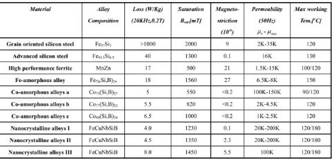
[image:4.595.49.291.189.305.2]As the main idea from SST is the high frequency operation mode, the selection of magnetic material used in the transformer is challenging to achieve the lower loss with high power density. Also this material configuration is highly affect its efficiency in the higher frequency operating mode. Those issues definitely raise the issue of insulation requirement to handle the raised heat form the High frequency operation. Table 1, shows the comparison of different material could be used in SST [17].
Table 1: different magnetic materials used in transformer.
As it is shown, the selection of the proper material is challenging depends on the application of SST used for. For example, the silicon steel as has high permeability but also has high losses under the high-frequency switching mode. So choosing the best magnetic materials should be made regarding its application.
Design structure of the transformer also affect its efficiency; the most common used structure is the solenoidal winding transformer where it is easier to manufacture and has lower cost compared to coaxial structure [30]. The solenoidal transformer structure could be Shell, Core or Matrix type [31], each of them has its specification, the Core-Type has the lower cost with easiest manufacturing process, but Shell-Type has higher mechanical protection for the winding, Matrix-Type is more complex compared to the previous types but it could be used for higher voltage transformer. Insulation design and Thermal issue are raised in SST, where this transformer is coming with the idea of low size lower weight transformer. [31] introduce the dry type of transformer design has even Fan-Cooled or Water-Cooled heatsink as the proper design for high power density design.
C. Reliability
Reliability of the SST is one of the most important factor that affect the introducing of this asset into the system as compared to the classical winding transformer, the reliability of SST is much lower than that of the line frequency transformer LFT, where the last is already used in the system since the introducing of the AC system by Tesla. SST is still a new generation, and its complex topology makes it fall into the reliability issue [24]. It is known that the reliability of any new system raise up as the technology matures. Using the control system is the main factor which will affect to the system reliability where many decisions could have made remotely and also all required measurement and instantaneous data could be measured by the control strategy used, so developing the control strategy will definitely increase the system reliability [25].
D. Effiicency
Efficiency of the transformer in the system is an important factor where the losses and efficiency are linked to
each other. As compared to the LFT, efficiency of the SST is still lower than that of LFT. According to the National Electrical Manufacturers Association NEMA [32], efficiency of the LFT have a rating of 30 kVA must be at least 97.3% which is higher than that of the SST. The main factor affecting the LFT efficiency are the winding and core loss, while SST has more than that the losses becomes due to the using of power electronic converter, presented as switching losses and conduction losses. A comparison made in [20], shows the efficiency of different SST topologies with different rating loads, the maximum achieved efficiency was 93.7% for a variable source converter with full load rating, which is still far from that of LFT.
V. CONCLUSION.
In the previous years, SST has received the attention off different academic and industrial sectors regarding its applications and benefits. This paper reviewed, generally, the state of art of SST, form the available topologies, HV SST to its efficiency in recent ways. In addition, the applications of SST are well explained to check and identify where and how the SST could work in different electric sections. It has been evident that using the SST in the distribution system could help in achieving the required smart grid. The paper also summarizes the most important challenges that are facing the applications of SST in the system and it shows that the most important development in SST will be evident with the development of the new generation of power electronic semiconductor.
SST has come a long way, and in reference to the previous efforts put on it, it is possible to now say that it is possible to replace the classical transformer with SST. However, its cost and reliability are still a main issue affecting this replacement.
REFERENCES
[1] A. Abu-Siada, J. Budiri and A. Abdou, "Solid State Transformers Topologies, Controllers, and Applications: State-of-the-Art Literature Review", Electronics, vol. 7, no. 11, p. 298, 2018. Available: 10.3390/electronics7110298.
[2] Ushkewar, S.; Dake, V.; Shinde, V. Designing of solid state pulse power modulator by fabrication of pulse transformer. In Proceedings of the 2017 Innovations in Power and Advanced Computing Technologies (i-PACT), Vellore, India, 21–22 April 2017; pp. 1–5.G. [3] Wrede, H.; Staudt, V.; Steimel, A. Design of an electronic power
transformer. In Proceedings of the IEEE 2002 28th Annual Conference of the Industrial Electronics Society, IECON 02, Seville, Spain, 5–8 November 2002; Volume 1382, pp. 1380–1385.
[4] Sabahi, M.; Goharrizi, A.Y.; Hosseini, S.H.; Sharifian, .B.B.; Gharehpetian, G.B. Flexible Power ElectronicTransformer. IEEE Trans. Power Electron. 2010, 25, 2159–2169.
[5] Sepahvand, H.; Madhusoodhanan, S.; Corzine, K.; Bhattacharya, S.; Ferdowsi, M. Topology selection for medium-voltage three-phase SiC solid-state transformer. In Proceedings of the 2014 International Conference on Renewable Energy Research and Application (ICRERA), Milwaukee, WI, USA, 19–22 October 2014; pp. 485–489 [6] Tiefu Zhao; Liyu Yang; Jun Wang; Huang, A.Q., "270 kVA Solid
State Transformer Based on 10 kV SiC Power Devices," Electric Ship Technologies Symposium, 2007. ESTS '07. IEEE , vol., no., pp.145-149, 21-23 May 2007.
[7] Falcones, S.; Mao, X.; Ayyanar, R. Topology comparison for Solid State Transformer implementation.In proceedings of the IEEE PES General Meeting, Minneapolis, MN, USA, 25–29 July 2010; pp. 1–8. [8] Kang, M.; Enjeti, P.N.; Pitel, I.J., "Analysis and design of electronic
[9] Xiaolin Mao, Raja Ayyanar, and Sixifo Falcones, “A Modular, Interleaved AC-AC Flyback Topology for Solid State Transformer”,
in Proc. FREEDM Annual Conference 2009, North Carolina StateUniversity, Raleigh, NC, May 18-19, 2009, pp. 221-224. [10] M. Qin, H.; Kimball, J.W. Solid-State Transformer Architecture
Using AC–AC Dual-Active-Bridge Converter. IEEE Trans. Ind. Electron. 2013, 60, 3720–3730.
[11] Vangen, K.; Melaa, T.; Adnanes, A.K., "Soft-switched high-frequency, high power DC/AC converter with IGBT," Power Electronics Specialists Conference, 1992. PESC '92 Record., 23rd Annual IEEE, vol., no., pp.26-33 vol.1, 29 Jun-3 Jul 1992.
[12] Sabahi, M.; Hosseini, S.H.; Sharifian, M.B.; Goharrizi, A.Y.; Gharehpetian, G.B. Zero-voltage switching bi-directional power electronic transformer. IET Power Electron. 2010, 3, 818–828. [13] Subhashish Bhattacharya, Tiefu Zhao, Gangyao Wang, Sumit Dutta,
Seunghun Baek, Yu Du, Babak Parkhideh, Xiaohu Zhou, and Alex Q. Huang, “Design and Development of Gen-1 Silicon based Solid State Transformer”, in Proc. FREEDM Annual Conference 2009, North Carolina State University, Raleigh, NC, May 18-19, 2009, pp. 69-74. [14] Rodriguez, J.; Jih-Sheng Lai; Fang Zheng Peng, "Multilevel inverters:
a survey of topologies, controls, and applications," Industrial Electronics, IEEE Transactions on , vol.49, no.4, pp. 724-738, Aug 2002.
[15] E. R. Ronan, S. D. Sudhoff, S. F. Glover, and D. L. Galloway, “A power electronic-based distribution transformer,” IEEE Trans. Power Delivery, vol. 17, no. 2, pp. 537–543, Apr. 2002.
[16] K. Fujii, P. Koellensperger, and R. W. De Doncker, “Characterization and comparison of high blocking voltage IGBT and IGCTs under hardand soft-switching conditions,” IEEE Trans. Power Electron., vol. 3, no. 1, pp. 172–179, Jan. 2008.
[17] She, X.; Huang, A.Q.; Burgos, R. Review of Solid-State Transformer Technologies and Their Application in Power Distribution Systems. IEEE J. Emerg. Sel. Top. Power Electron. 2013, 1, 186–198. [18] Grider, D.; Das, M.; Agarwal, A.; Palmour, J.; Leslie, S.; Ostop, J.;
Raju, R.; Schutten, M.; Hefner, A. 10 kV/120 A SiC DMOSFET half H-bridge power modules for 1 MVA solid state power substation. In Proceedings of the 2011 IEEE Electric Ship Technologies Symposium, Alexandria, VA, USA, 10–13 April 2011; pp. 131–134. [19] Qin, H.; Kimball, J.W. Solid-State Transformer Architecture Using
AC–AC Dual-Active-Bridge Converter. IEEE Trans. Ind. Electron. 2013, 60, 3720–3730.
[20] Qin, H.; Kimball, J.W. A comparative efficiency study of silicon-based solid state transformers. In Proceedings of the 2010 IEEE Energy Conversion Congress and Exposition, Atlanta, GA, USA, 12– 16 September 2010; pp. 1458–1463.
[21] Madhusoodhanan, S.; Tripathi, A.; Patel, D.; Mainali, K.; Kadavelugu, A.; Hazra, S.; Bhattacharya, S.; Hatua, K. Solid-State Transformer and MV Grid Tie Applications Enabled by 15 kV SiC IGBTs and 10 kV SiC MOSFETs Based Multilevel Converters. IEEE Trans. Ind. Appl. 2015, 51, 3343–3360.
[22] D. Dujic, C. Zhao, A. Mester, J. K. Steinke, M. Weiss, S. L. Schmid, T. Chaudhuri, and P. Stefanutti, “Power electronic traction transformer: Low voltage prototype,” IEEE Trans. Power Electron., vol. 28, no. 12, pp. 5522–5534, Dec. 2013.
[23] X. She, A. Q. Huang, F. Wang, and R. Burgos, “Solid state transformer interfaced wind energy system with integrated active power transfer, reactive power compensation, and voltage conversion functions,” IEEE Trans. Ind. Electron, vol. 60, no. 10, pp. 4512– 4524, Oct. 2013.
[24] J. van der Merwe and H. Mouton, "The solid-state transformer concept: A new era in power distribution", AFRICON 2009, 2009. Available: https://ieeexplore.ieee.org/document/5308264
[25] A. Ipakchi and F. Albuyeh, “Grid of the future,” IEEE Power and EnergyMagazine, March / April 2009.
[26] W. McMurray, “Power converter circuits having a high-frequency link,” U.S. Patent 3 517 300, Jun. 23, 1970.
[27] J. W. Kolar, J. Huber, Th. Guillod, D. Rothmund, D. Bortis, F. Krismer, "Smart (Solid-State) Transformers Concepts/Challenges/Applications," Power Electronic Systems Laboratory, Zurich, 2016. Available: https://www.pes-publications.ee.ethz.ch/uploads/tx_ethpublications/2016_PCIM_SST_ Keynote_PCIM_2016_as_published_JWK_130516.pdf
[28] K. Fujii, P. Koellensperger, and R. W. De Doncker, “Characterization and comparison of high blocking voltage IGBT and IGCTs under hardand soft-switching conditions,” IEEE Trans. Power Electron., vol. 3, no. 1, pp. 172–179, Jan. 2008.
[29] J. W. Palmour, J. Q. Zhang, M. K. Das, R. Callanan, A. K. Agarwal, and D. E. Grider, “SiC power devices for smart grid systems,” in
Proc. Int. Power Electron. Conf., 2010, pp. 1006–1012.
[30] S. Baek, Y. Du, G. Y. Wang, and S. Bhattacharya, “Design considerations of high voltage and high frequency transformer for solid state transformer application,” in Proc. 36th Annu. IEEE IECON, Nov. 2010, pp. 421–426.
[31] G. Ortiz, M. Leibl, J. W. Kolar, and O. Apeldoorn, “Medium frequency transformer for solid-state-transformer application— Design and experimental verification,” in Proc. IEEE PEDS, Apr. 2013, pp. 1285–1290.