Figure 6 Immunochromatography slide for once-only use near the subject testing to detect abused drugs. C"control, THC"tetrahydrocannabinol, a metabolite of cannabis.
‘sticks’ which use immunochromatography. The prin-ciple is that the sample, e.g. urine, is applied to the stick which is then developed, e.g. by capillary attrac-tion, the analyte of interest binding at a zone where there are antibodies. There are sometimes built-in
positive and negative controls. When the antigen and antibody combine they develop a visible colour spot or band which conRrms the presence of the com-pound of interest (Figure 6). While these devices are expensive and inaccurate they have the beneRt of immediacy which may be clinically acceptable pro-vided they are used appropriately.
The Future
Chromatography has maintained its role in certain niches in clinical laboratories. Interest in manufac-turer-supplied solutions for chromatography, par-ticularly LC, exists and compensates for the lack of skill base. For difRcult low throughput analyses this may be how developments will be consolidated. Capillary zone electrophoresis could impact on much current LC work but again skill and capital costs militate against this. If accuracy rather than impreci-sion becomes a major clinical laboratory issue, as it may, then the inherent accuracy of chromatography probably linked to mass spectrometry will provide a role for deRnitive methods and may provide a role for methods used in routine laboratories.
See also: II/Chromatography: Thin-Layer (Planar): Mass Spectrometry. III/ Toxicological Analysis: Liquid Chromatography.
Further Reading
Baselt RC (1987)Analytical Procedures for Therapeutic Drug Monitoring and Emergency Toxicology, 2nd edn. Massachussetts: PSG Publishing.
Bowers LD, Ullman MD and Burtis CA (1994) Chromatog-raphy in: Burtis CA and Ashwood ER (eds)Tietz Text-book of Clinical Chemistry, 2nd edn. Philadelphia: WB Saunders.
Kuenigsberger RU (1988) High performance liquid chromatography. In: Williams DL and Marks V (eds) Principles of Clinical Biochemistry, 2nd edn. London: Heinemann.
COAL: FLOTATION
B.K. Parekh, University of Kentucky, Lexington, KY, USA
Copyright^ 2000 Academic Press
Introduction
The process of frothSotation for upgrading the qual-ity of coal by removing mineral matter (ash and
Figure 1 Hydrophobicity of various coals as a function of per-centage carbon based on the contact angle technique. (Aplan (1989), courtesy of SME, Littleton, Colorado, USA.)
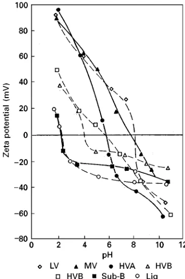
Figure 2 Zeta potential and point-of-zero charge (PZC) of coals of various ranks. (Aplan and Arnold (1991), courtesy of SME, Littleton, Colorado, USA.)
Recovering Rne coal offers important economic and environmental functions. In economy terms, the plant recovers an extra amount of clean coal that would have otherwise been discarded to the impoundment. Recovering the clean coal reduces the amount ofRnes to the ponds, and improves the quality of recycled water.
The basic coal Sotation technology has been de-rived from ore Sotation, where the technology has been extensively used. TheRrst froth Sotation plant for coal was established in the United Kingdom in 1920 and theRrst US plant was established in 1930. FrothSotation technology has made substantial pro-gress over the lastRfty years.
Coal is a solid combustible material and exists in the ground along with impurities. Coal, being com-posed of carbon elements, is hydrophobic in nature and thus is a good candidate for the froth Sotation technique. The impurities present in coal basically consist of clays, quartz, calcite, dolomite, pyrite, chlorite, etc. which are hydrophilic in nature and thus, can be eaily removed in an aqueous medium. Pyrite minerals present in coal have an ambivalent character and are sometimes difRcult to remove by theSotation technique.
Hydrophobicity of Coal
The hydrophobicity of coal varies with the rank of the coal and oxygen functional group present in the coal. The high volatile bituminous coals are the most hy-drophobic, whereas lignite is the least hydrophobic. One technique to quantify the hydrophobicity of coal is through measuring contact angles of water on coal surfaces. Figure 1 shows the contact angle data of water on various coals. Note that the maximum con-tact angle or the hydrophobicity occurs at&88% C, and the high-carbon content anthracite coals are less hydrophobic.
Zeta Potential of Coal
[image:2.568.311.494.391.667.2]Figure 3 A line diagram of a column flotation cell.
Figure 4 Schematic diagram of the MicrocellTM. (Yoonet al.
(1992), courtesy of Gordon and Breach Science Publishers.)
Reagents
The purpose of Sotation reagents is to provide a strong hydrophobic surface and to create small relatively stable bubbles. For coal Sotation, in general, only the collector and frother reagents are used.
Collectors
Theoretically speaking, the highly hydrophobic coals (containing 85}90%C) should not require any collec-tor. In practice, a small amount of either No. 2 fuel oil or kerosene is used as collector. The amount of a col-lector required varies from a low (0.11}0.2 kg t\1) for a high rank coal to a high (1.0}2.0 kg t\1) for a low rank coal.
Frothers
The primary function of the frother is to produce a large quantity of Rne size bubbles. The bubbles should be able to carry the coal to the surface without breaking, and once out of the Sotation machine, it should break down. The most commonly used frothers for coalSotation are either pure alcohol, e.g. MIBC (methyl isobutyl carbinol) or a mixture of various alcohols and the polypropylene glycol-based frothers. The amount of frother required varies from 0.2 to 0.5 kg t\1.
Depressant
The function of depressant is to suppress the S ota-tion of one component of the mixture of solids by adding a speciRc chemical. In coal Sotation, pyrite usually Soats along with the coal. Many papers have been published on the subject; however, Chaudhari and Aplan, and Xu and Aplan, have con-ducted a detailed investigation of various reagents for depressing Sotation of pyrite. They concluded that there is no universal reagent for depressing pyrite. In the coal industry, pyrite depression is not practised; however, in the future this might become an important step for the coal industry to survive.
There are some other variables for Sotation, such as pH, dispersing reagents, percentage solids, particle size, etc. However, in the coal industry, very little or no attention is given to these factors. Readers inter-ested should refer to Aplan’s work.
Flotation Machines
The coal industry uses either mechanical or column cells.
Mechanical
[image:3.568.307.504.463.681.2]Figure 5 Schematic of Jameson cell. (Courtesy of Richwood Industry, Huntington, West Virginia, USA.)
[image:4.568.297.509.272.656.2]Figure 6 Performance data of the Jameson cell at the laborat-ory, pilot, and full scale. (Honakeret al. (1999), courtesy of SME, Littleton, Colorado, USA.)
Figure 7 Metallurgical performance achieved by the three col-umn flotation technologies and the advanced flotation washability (AFW) analysis on the basis of (A) product ash and (B) total sulfur contents (feed ash: 42.6%; total sulfur: 0.86%). (Mohanty and Honaker (1999), courtesy of Elsevier Science.)
larger volume machines (3000 ft3or 84 m3). For coal Sotation, mechanical cells are usually arranged in banks of four to six cells in an ‘open-Sow’ arrange-ment.
Column
The columnSotation cell which has achieved success in the mineral industry was introduced to the coal industry in the 1990s. The machine consists of a long (&6 m) vertical tube ranging from 2.4 to 3.0 m in
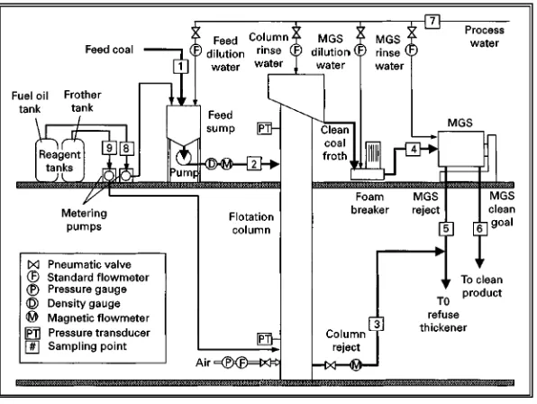
[image:4.568.56.274.509.666.2]Figure 8 Schematic drawing of the combined advanced flotation/enhanced gravity separation circuit. (Luttrellet al. (1998), courtesy of Gordon and Breach Publishers.)
columns were installed in the USA at the Powell Mountain Coal Company, Virginia.
The ‘Mocrocel’ columnSotation developed at the Virginia Polytechnique and State University uses an inline mixture to generateRne bubbles in the column. In this column, a part of the reject stream is passed through the inline mixture along with the frother and air to generate Rne bubbles. Figure 4 shows a dia-gram of the MicrocellTMcolumn.
The Static TubeSotation system developed at the Michigan Technology University uses corrugated plates packed inside the column to break up large bubbles into a smaller size bubble. The machine does not utilize any special bubble-generating device.
The Jamison cell is a column cell that is much shorter than any of the columns described earlier. As shown inFigure 5, the Jamison cell utilizes a pressur-ized feed stream injected through a long tube called the downcomer to draw atmospheric air into the device. The resulting jet formed is discharged into a short column where coalSoats to the surface and tailings are discharged at the bottom. Wash water is generally added through a tray located above the froth phase. Currently, quite a few Jamison cells are being used in Australia and a few coal preparation plants in the USA. Figure 6 compares the separa-tion performance as a funcsepara-tion of ash content for a coal using the laboratory-, pilot- and full-scale Jamison cell units. The L-shape of the release curve indicates that the impurities in the coal are well liber-ated. The laboratory- and pilot-scale units were near-ly able to produce the performance of the release
analysis. An ash content reduction of about 40}45% was achieved while recovering 77% of the combust-ible material, which equates to an ash rejection of about 95%.
Mohanty and Honaker published a comparative evaluation of the three leading columnSotation tech-nologies. According to them, the packed column pro-duced the best separation performance owing to its ability to support a deep froth zone. However, be-cause of the absence of an air-sparging system and consequently larger bubbles, the solids-carrying capa-city of the froth was minimal. On the other hand, the solids-carrying capacity or solids throughput achieved with the Jameson cell, was found to be maximal. The MicrocellTMachieved maximum carry-ing capacity while providcarry-ing a high energy recovery with a reasonably low amount of reagents.Figure 7 shows the combustible recovery (amount of combust-ible material) as a function of product ash and total sulfur obtained for a coal using the three column technologies. The AFW (advanced Sotation washa-bility) is a limiting curve indicating the possible ash and sulfur that could be achieved using frothSotation technology. Note that the packed column provided both low ash and sulfur; however, the MicrocellTM and Jameson cell both provided high combustible recovery.
Figure 9 Separation performance obtained using the flotation column and combined flotation column/MGS circuit. (Luttrellet al. (1998), courtesy of Gordon and Breach Publishers.)
Figure 10 Optoelectronic tailings detector. (Meenan (1999), courtesy of SME, Littleton, Colorado, USA.)
hydrophobic and some are hydrophilic in nature. In the case of coal, pyrite is always associated with some carbon which affords it hydrophobic and makes it Soat with coal. Luttrell et al. conducted studies on combining columnSotation with an advanced gravity separation technology to remove pyrite from coal. The process Sowsheet for the two-stage circuit is shown in Figure 8. A MicrocellTM Sotation column froth product after derating was sent to a multi-gravity separator (MGS) developed by the Mosley Ltd, UK. The MGS is similar to the shaking table, except that the particles in the SowingRlm are also subjected to centrifugal forces.Figure 9compares the performance of the Sotation column alone to that obtained using the combinedSotation column/MGS circuit. The rejection of pyritic sulfur improved from 60.5% to 83.6% and ash rejection improved from 83.8% to 87.7% using the combined techniques. Using the MGS unit, the loss of coal (energy) was very low, in the order of 2}3% points.
CoalSotation is a manually operated process. Re-cently, process optimization has been achieved through more efRcient circuit designs and innovative sensor development. Some new approaches have been developed in the sensor area, which help in designing a controlled reagent delivery system. The Consol Co. has developed an inexpensive optical-based system shown in Figure 10. The main components of the detector are a glass tube, a photoconductor, an opaque barrier, and a light-emitting diode (LED). The light from the LED is reSected from the slurry to the main photoconductor. The photoconductor changes resistance in proportion to the light reSected from the tailing stream. The higher the tailings slurry ash
con-tent, the more light reSected back to the photocon-ductor and the lower the resistance.
A machine-vision or ‘video-based’ analyser system has also been successfully tested by Virginia Polytech-nique Institute and State University. The video-based system could detect changes in slurries over an oper-ating range of 60}90% ash.
Conclusion
In summary, coal Sotation, column Sotation has shown signiRcant advantages from the technical and economic points of view. A combination of column with advanced gravity separators provides a much cleaner coal with low ash and pyritic sulfur contents. In the future, all new coal preparation plants will utilize column technology along with process optim-ization and sensors for the economic recovery of ultra-Rne coal particles.
Further Reading
Adel GT, Luttrell GH, Cruz EB and Dunn PL (1997) In-plant testing of a video-based coal slurry ash analyzer. Presented at the 14th International Coal Preparation Conference, pp. 39}156.
Aplan FF and Arnold BJ (1991) Flotation. In: Leonard JW (ed.) Coal Preparation, pp. 450}485. Littleton, CO: Society of Mining, Metallurgy, and Exploration, Inc. (SME).
Arnold BJ and Aplan FF. (1989) The hydrophobicity of coal macerals.Fuel68: 651}658.
Bury E. and Bicknell A (1921) PuriRcation of coal by froth
Sotation.Colliery Guardian21: 337.
Bury E, Broadbridge W and Hutchinson A (1920) Froth
Sotation as applied to the washing of industrial coal. Institute of Mining Engineers60: 243}253.
Chaudhari V and Aplan FF (1992) Pyrite depression during coalSotation}Part I. Inorganic.Mining and Mineral Processing Journal9: 51}56.
Davis DH (1948) FrothSotation of minus 48 mesh bitumi-nous coal slurries.Transactions AIME177: 320}337. Gutierez JA, Purcell RJ and Aplan FF (1984) Estimating the
hydrophobicity of coals.Colloids and Surfaces12: 1}25. Honaker RQ, Patwardhan A, Mohanty MK and Bhaskar K (1999) Fine coal cleaning using the Jamison cell: The North American Experience. In: Parekh BK and Miller JD (eds) Advances in Flotation Technology, pp. 331}341. Littleton, CO: Society of Mining, Metal-lurgy, and Exploration, Inc (SME).
Horsley RM and Smith HG (1951) Principles of coalS ota-tion.Fuel30: 54}63.
Luttrell GH, Venkatraman P and Yoon RH (1998) Re-moval of hazardous air pollutant precursors by ad-vanced coal preparation. Coal Preparation 19: 2243}2255.
Meenan, GF (1999) Modern coalSotation practices. In: Parekh BK and Miller JD (eds)Advances in Flotation Technology, pp. 309}319. Littleton, CO: Society of Mining, Metallurgy, and Exploration. Inc. (SME). Mohanty MK and Honaker RQ (1999) A comparative
evaluation of the leading advancedSotation technolo-gies.Minerals Engineering12(1): 1}13.
Parekh BK, Bland AE and Groppo JG (1990) A para-metric study of columnSotation.Coal Preparation8: 49}60.
Yang DC (1986) Column frothUotation. US Patent No. 4,592,834 (January 1986).
Yoon RH, Luttrell GH, Adel GT and Mankosa MJ (1992) The application of microcell column toRne coal clean-ing.Coal Preparation10: 177}188.
Xu DD and Aplan FF Joint use of metal ion hydroxy compounds and organic polymers to depress pyrite and ash during coalSotation.
COBALT ORES: FLOTATION
See III / NICKEL AND COBALT ORES: FLOTATION
COLLOIDS: FIELD FLOW FRACTIONATION
G. Karaiskakis, University of Patras, Patras, Greece
Copyright^ 2000 Academic Press
Introduction
When dealing with colloidal materials, the para-meters of size and size distributions are needed, because many physicochemical processes, like ag-gregation and deposition on solid surfaces, are in-Suenced by the size and size distributions of these materials.
For the analysis of submicron or supramicron colloidal particles, a sedimentation process, either under gravity or with centrifugal force, is necessary to sort different diameter particles into classes, and then to obtain an average size and a size distri-bution. Among the successful techniques used for this purpose, are electrophoretic mobility and the methods of size exclusion chromatography,
hydrodynamic chromatography and Reld-Sow frac-tionation (FFF).
FFF is a family of separation methods introduced by Giddings in 1966, but several groups all around the world have contributed signiRcantly to the devel-opment. The various subtechniques of FFF are best suited to the separation and characterization of collo-idal materials and macromolecules, including biolo-gical components ranging in size from proteins to living cells, environmental colloidal particles, as well as industrial polymers and colloids, powders, latexes and emulsions.