1
I
/;~~5.11
ElC NO. DATE ElC NO.I
'--"r
~ fiOl1
'", .... ..-.I
I
I
I
t
i i i i
I
I
I
I
I
I
PRODUCT SPECIFICATION
PRIAM SMART AND SMART-E INTERFACE
SHEET
AND
REVIS IONTABLE
SHT
c
i ii iii iv 1 2 3 4 5 6 7 8 9 10 11 12 13REV
A A A A A A A A A A A A A A A A A ASHT
1415
16 17 18 19 20 21 22 23 24 25 26 27 28 29 30 31REV
AI
A A I A I A A ; & A A A A A A , AI A • A A, A
.n. .n. ft .M. I
.
SHT
32 33 34 35 36 37 138 39 40 41 42 43 44 45 46 47 48 49REV
A A A A A A A A A A A A A A A A A ASHT 50 51 52 53 . 54 55 56 57 58 59 60 61 62 63 64 65 66 67
REV
A A A A A A A A A A A A A A A A A ASHT
68 69 70 71 72 73 74 75 76 77 78REV
A A A A A A A A A A AeLI ..
I I I I I I
f
11 I I I I II I I
I
en.
,
! IREV
IHT
, ' . " ," .. J ~ "' "
REV
';' ~"" >;" <"
.' .
TITLE
PRODUCT SPECIFICATION
-C
PRIAM SMART/sMART-E INTERFACF
::D
-DESIGN SCALE
-
>
DETAIL SHEET COVER OF 83
3:
OFTG CHI<
REV
300115I.
II.
III.
IV.
V.
,PRIAM SMART INTERFACE AND SMART-E INTERFACE PRODUCT SPECIFICATION
INTRODUCTION
A.
Bec.
D. E. F. PurposeApplicable Documents General Description Features
Additional Features of the SMART-E Interface SMART-E Planned Enhancements
PRODUCT DESCRIPTION
A.
B.c.
D. E. F.Physical Characteristics Power Requirements
Environme~tal Characteristics Reliability
Controls - SMART Interface Controls - SMART-E Interface
ELECTRICAL I~~ERFACE
A. B.
Interface Signals
Data Transfer To/From the "Interface
FUNCTIONAL INTERFACE
A. B.
c.
D. E. F.Command Initiation
User-Accessible Registers Disc Addressing Methods Interleaving
Defect Mapping
Error Retry Technique
COMMAND DESCRIPTION
A. Interface Configuration and Control Commands
Read Mode
Specify Mode (SMART-E Only) Completion Acknowledge Read Drive Type
Read Drive Parameters Read Internal Status Software Reset
B.
C.
D.
E.
Format Disc Commands 49
Format Disc With Defect Mapping 50 Format Disc Without Defect Mapping 51 Format Cylinder Without Defect Mapping 51 Format Track Without Defect Mapping 52
Write ID 53
Read ID 54
Read ID Immediate 55
Read Skip Defect Field 55 Write Skip Defect Field 56
Defect Mapping Commands
Specify Bad Sector Specify Bad Track Read Defect Directory Write Defect Directory
Data Transfer Commands
Write Data Read Data
Disc Motion and Drive Control Commands
Sequence Up-Return Sequence Up-Wait Sequence Down Seek
Drive Restore Read Drive Status
57 57 58 58 59 59 59 61 63 63 63 64 64 65 65
F. Disc Data Initialization and Verification Commands 67
G.
Write Disc - Full Track Write Cylinder - Full Track Write Full Track
Verify Disc Verify Cylinder Verify Track Verify Data Verify ID
Diagnostic Commands
Write Buffer Read Buffer
Transfer Parameter to Result ID Buffer Transfer Test
APPENDIX A - Disc Format
LIST OF FIGURES
Page
Figure 1 SMART Jumper Locations 7
Figure 2 SMART-E Jumper Locations 8
Figure 3 Register Read AC Characteristics 13
Figure 4 Register Write AC Characteristics 14
Figure 5 Data Request AC Characteristics 14
Figure 6 SMART-E Register Write AC Characteristics 15
Figure 7 SMART-E Data Requests 16
Figure 8 SMART-E Regi~ter Read AC Characteristics 16
Figure 9 SMART-E Direct Mode Data Requests 17
Figure 10 S~.ART-E Buffered Mode Data Requests 18
30011SA
LIST OF TABLES
Table 1 PRIAM Disc Drive Characteristics 2
Table 2 Recommended Drivers/Receivers 11
Table 3 Interface Connector Pin Assignment 12
Table
4
Command Summary 20Table 5 Control Register Assignment 21
Table 6 SMART Interface Status Register 22
Table 7 Transaction Status Register 24
Table 8 Completion Code Summary 25
Table 9 Drlve Fault Condltlons
.
\ ..
30Table 10 SMART/SMART-E Command Delays 35
Table 11 Defect Directory Format 36
Table 12 Defect Directory Entry Format 36
Table 13 Alternate Areas (Cylinders) by Drive Type 36
Table 14 ID Control Field Definition 37
Table 15 Error Recovery Strategy 38
Table 16 SMART-E ECC Characteristics Summary 39
Table 17 Common SMART-E Mode Byte Values 42
Table 18 Mode Register (SMART-E Only) 43
Table 19 Drive ID Assignments 46
Table 20 Drive Status Bit Definition 66
Table 21 Memory Address Ranges 72
Table Al Defect Record Format 75
Table A2 Sector Format 76
Table A3 Sector Format Summary - 3350/6650/15450 78
Table A4 Sector Format Summary - 3450/7050 78
Table AS Sector Format Summary - 1070 78
I~ 'INTRODUCTION
A. Purpose
This specification describes the performance, the logical interface, the electrical interconnection, and the physical interconnection of the PRIAM SMART Interface and the PRIAM SMART-E Interface. This document provides the technical specifications required by users to connect the PRIAM SMART or SMART-E Interface to a host system with or without the use of a Direct Memory Access (DMA) port. For specific drive characteristics, see Table 1; for additional product detail, refer to the applicable product specifications.
B. Applicable Documents
PRIAM Product Specification 3350, 6650, and 15450 PRIAM Product Specification 3450 and 7050
PRIAM Product Specification 1070 PRIAM Interface Specific8tion
\
c.
General DescriptionFor the purposes of this document and to eliminate text redundancies, the S~ART and SMART-E will be referred to as the Interface, except where the two devices differ.
The Interface is a complete preprogrammed microprocessor based
controller for the entire line of PRIAM Winchester disc drives. Up
to four drives in any combination may be interconnected. The controller supports a variety of Read Sector, Write Sector, and
Format commands. The data for the sector operations is transferred
across an 8-bit parallel bidirectional data bus. The data transfers
may be either programmed I/O or DMA transfers. Thus, the Interface performs the entire function of detailed disc control while
presenting to the host a basic and cost effective interface. The Interface board may be mounted separately or attached to a PRIAM disc drive, either 8-inch or 14-inch.
The individual disc drive characteristics are shown in Table 1. Data capacities specified are based upon the number of eight bit bytes that may be recorded on a track. Tnis unsectored capacity does not include any allowance for gaps or any format overhead. However, allowance is made for the 36 byte defect record.
300115A
Model 3350-10 6650-10 15450-10 3450-10 7050-10 1070-10 Disc Size 14" 14" 14" 8" 8" 8"
TABLE 1 - PRIAM DISC DRIVE CHARACTERISTICS
No. of Data Heads 3 3 7 5 5 4
No. of Servo Heads 1 1 1 1 1
None
*
Data Transfer Rate ME/Sec 1.04 1.04 1.04 0.8 0.8 0.9 Usable
Bytes Bytes per Track per Cyl.
20,124 60,372
20,124 60,372
20,124 140,868
13,404 67,020
13,404 67,020
14,256 57,024
Bytes per Drive
33,868,692 67,677,012 157,913,028 35,185,500 70,303,980 10,834,560 Cyl. per Drive 561 1121 1121 525 1049 190
*
Stepper motor controlled positioner.D. Features
1. Controls up to four PRIAM disc drives.
2. Supports all PRIAM 8-inch and 14-inch disc products in any combination.
3. Designed for easy attachment to the typical microprocessor bus.
4. Does all bit serialization and format related functions. The host uses a simple byte-wide interface.
5. User-selectable sector sizes of 128, 256, 512, or 1024 bytes.
6. Full sector buffering which supports data transfers at any rate below 2 megabytes per second.
7. Both interrupt driven and polled operation are supported.
8. On-board 16-bit CRC on both ID header and data (SMART). On-board 32-bit ECC on both ID header and data (SMART-E).
9. Automatic alternate sector assignment and read or write sector logic handle media defects transparent to the host.
10. Overlapped commands are supported. For example, three drives may be seeking, while seeking, reading, or writing on the fourth drive.
[image:7.621.30.540.79.320.2]11. The Interface supports implied operations. For example, issuing a Read Command to a drive in which the disc is not turning will cause the drive to Sequence Up, Restore, Seek to the desired cylinder, Select the appropriate head, and Read the desired sector.
12. Versatile verify functions may be used for seek verification,
sector data verification, track data verification, cylinder data verification, and complete disc data verifications.
13. Resident microdiagnostics.
E~ Additional features of the S~~RT-E Interface
1. High p~rformance microprocessor based.
2. Provides error correction (ECC).
3. Supports logical sector addressing.
\
4. Supports interleaving of sectors on drive.
5. Allows direct (non-buffered) data transfers.
6.
Generates/tests parity on data bus.7. 2K-byte disc data buffer (SMART is lK-byte).
F. SMART-E Planned Enhancements
1. Daisychain capability to selected tape devices for
straight-forward, inexpensive backup using common controller.
2. Full-track read and write (i.e., single-sector track) for
large-block, high-speed data transfer.
3. Software user-selectable sector size for format flexibility.
4. On-track sector-sparing option for throughput efficiency.
NOTE: The SMART/SMART E Interfaces are not disc data format
compatible. The drive must be formatted before use by the
--,--~-~
~-~--~---i:)t:~t:~L.t:u ~UL.t:l.~d~t:.
300115A
II. PRODUCT DESCRIPTION*
A. Physical Characteristics
The Interface is assembled on a single printed circuit board (13.75 by 8.30 inches) which may be mounted on either a 14-inch or 8-inch drive. There are three connectors: one for the host interface (40 pins), one for the drive interface (50 pins), and a third for DC power (2 pins). The host ir.terface cable may be up to 25 feet in length.
The connector and cable types are as follows:
Interface
Host
Drive
Power
Connector on SMART /SMART E
3M 3432-1302 or
J3erg 65823-085
3M 3433-1302 or
Berg 65847-045
AMP 640389-2 or
Panduit HLAS156-2
B. Power Requirements
Connector on Interface Cable
3M 3417-7040 or
Spectra Strip 802-140-002
3M 3425-7050 or
SAE RD6350-RSC
Molex
Series 2139 09-50-3021 with pins: Series 2478 08-50-0105
or Methode
3300-102 wi th pins: 3400-111
SMART: + 5 VDC,
.!.
5%, 3 AMP maximumSMART-E: + 5 VDC,
.!.
5%, 3.5 AMP maximumC. Environmental Characteristics
1 • TEMPERATURE
Cable Type
3M 3476/40 or
Spectra Strip 455-276-40
3M 3365-50
a. Equipment Operational: 100 C to 400 C (570 F to
1040 F).
b. Equipment Non-operational: -400 C to 600 C (-400 F
to 1400 F).
4
2. HUMIDITY
a. Equipment Operational: 20% to 80% relative humidity, with
a wet bulb temperature limit of 260 C (780 F) without
condensation.
b. Equipment Non-operational: 20% to 80% without condensation~
3.. ALTITUDE
a. Equipment Operational: From 1000 feet below sea level to
7000 feet above sea level.
b. Equipment Non-operational: From 1000 below sea level to
40,000 feet above sea level.
*
Specifications and characteristics provided in this document are subject tochange without notice,
D. Reliability
1. MTBF
The Interface has an expected mean time between failures (MTBF) of 8000 power-on hours.
2. MTTR
The Interface is a field replaceable unit with a mean time to
repair (MTTR) of less than 1/4 hour.
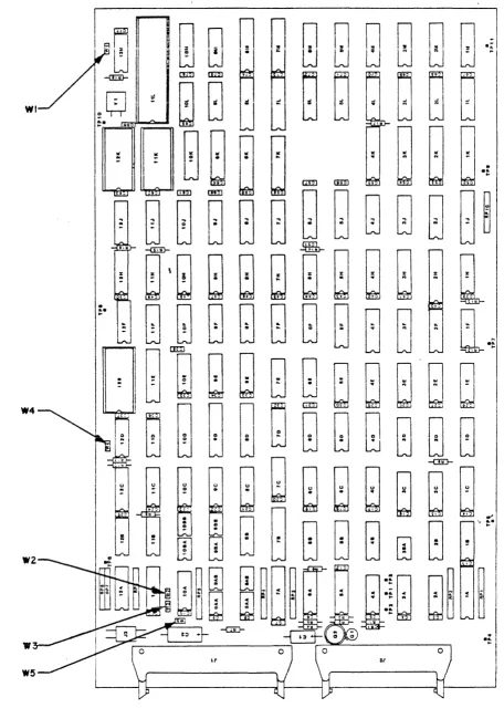
E. Control Jumpers for SMART Interface (See Figure 1)
1. WI
If jumper WI is in the A position, PROM 12K is selected as a
2732; this jumper is selected by a PCB trace. ,;
2. W2, W3, W4
If these jumpers are out, the PRIAM open loop write clock or A level interface is selected.
If these jumpers are installed, the PRIAM closed loop write clock or B level interface is selected.
3. WS
This jumper, when installed, enables the Head 4 line used on the DISKOS 3450 and the DISKOS 15450.
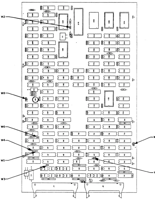
Fe Control - Jumpers for SMART-E Interface (See Figure 2)
1. WI
If jumper WI is in the A to B posItIon, the SMART-E Interface
becomes compatible with the SMART Interface with respect to the operation of the DTREQ/, HRD/, and HWR/ lines. This
configuration does not support Direct Mode data transfers.
If jumper WI is in the B to C position, the SMART-E Interface will support Direct Mode data transfers. However, in this
configuration, the SMART-E Interface is not compatible with the SMART Interface with respect to the DTREQ/, HRD/, and HWR/
lines. Position B to C is the recomended position.
2. W2
Reserved for future use. This jumper is not required.
3. W3
This jumper, when installed, enables the Head 4 line, used on the DISKOS 3450 and the DISKOS 15450.
4. W4, W5, W6
If these jumpers are out, the PRIAM open loop write clock or A
level interface is selected.
If these jumpers are installed, the PRIA~ closed loop write
clock or B level interface is selected.
5. W7
If jumper W7 is in the B to C position, even parity IS enabled
on the host interface bus.
.;
If jumper W7 IS in the A to B position, parity IS disabled on
the host interface bus.
6. W8
Reserved for future use. This jumper should be installed In the
B position.
300115A
FIGURE 1. SK~RT Jumper Locations
[image:12.613.52.508.38.678.2]~?
·
:I
~
·
..
I~
-<6}-
..
-<!iD-~
!
I
>
·
I~
tJ
[]
D
W2 :
...
CIe
...
2 eo
>
:
I
>..
eo..
I~
~
~
B~
~} !
I
~?
..
I
~
!:!I
2 ~
I~>
..
..
..
..
..
..
}
II
?
!'E]
~~
Co)I
~?
!
I~?
..
..
2 :!~?
!I
~?
..
~I
!~
:
I
2
!I~}
..
~
-an-}
!
I
}
..
I~
~~
Co)]
~~·
I
~
..
: ! ! CI
;j?
fI
~}
..
...I
~
..
..
}
~I
~
: J ~} ~..
-caD-~
zI
}
..
I~?
!I
}
QI
~~
uI
~?
•I
~
'"I
: ! ! ! : !
~?
zI
~~
..
I
~
·
)
~? •I
~
uI
~
!I~?
::I
!
·
! ! ! ...-c!ID- -C!D- e;.
}
!
I
>..
..
I
~?
!~
:
I
~?
_
u :! J~?
!I
~
:
+'-~I~
--aD-
-c!D-...
I
?
..
~
'[]
we
..
..
~0J2
...I
~?
:~2
=
:
~
:
~2
=
..
~?
!I
~?
...1 2
.
2 !:!~
~}
!
I
?
!lSi
!~
u ~I
?
!a?
c ~.
-
I,J>
iI
?
..
r >..
?
uru
·
I
~
:\
..
i
·
·
.
•....
I
-(!'E)- -c!D- [ I lIP: I ...
?
zI
~?
..
I
~?
·
~2
~I
?
I~~
::I
.
·
·
-I!iD-I
..
I
~
..
Iff
eI
l
~Itt
: 12 :.I
..
...yW7
..
I
~>
..
I
}
i~~
~I
~
·
I~>
:I
I·
..
·
·
..
'I
~
II
?
CII
?
~I~?
: ::I.. .. :
·
CI
-mD-...
I
~
~I
2
0I~
: :...
..
-<!ill-I
?
I
~
..
..
I
m
t i U, I
-<!ZD-;-;
wrum
~
2I 2
~ 1§?
·
..
, 1 I WI
rumrurnfi
~l[[]wFf
!I
? ~§
W II !!~ I
®
-<dtr=
!!~ ~:;
..
,Figure 2. SMART-E Jumper Locations
[image:13.617.53.549.17.668.2]tII'. ELECTRICAL INTERFACE
A. Interface Signals
The interface signals are defined in this section. Table 3 shows the
connector pin assignment. All Interface signal connections are via a
single 40 pin ribbon cable connector. See Table 2 for the
recommended drivers and receivers.
1. HCBUSO thru HCBUS7
This is the host bus. It is a high-active 8-bit wide
bidirectional bus used to transfer control, status information and data. Data is transferred across this bus by successive operations with the Disc Data Register. The most significant
bit is HCBUS7. The bus is TRISTATE bidirectional with the
drivers enabled when the HRD signal is active. The receivers are enabled when the HRD signal is inactive.
Recommended termination for this bus is a 330 ohm resistor to +5
volts and a 390 ohm resistor to ground. Note: High current
drivers (as listed in Table 2) are required to drive the HCBUS
lines.
2. HCBUS8 (SMART-E Only)
This is the host bus parity line. If SMART-E jumper W7 is in
the A position, data transfers accross the host ~us (HCBUSO
through HCBUS7 including HCBUS8) must have even parity.
Recommended termination for this signal is a 330 ohm resistor to
+5 volts and a 390 ohm resistor to ground~
3. HRD/
This low-active signal gates the contents of the selected
register (decode of HAD2, HAD 1 , HADO) onto the HCBUS. See Table
5 for register decode assignment. This signal is terminated at
the Interface with a 220 ohm resistor to +5 volts and a 330 ohm resistor to ground.
4. HWR/
This low-active signal gates the contents of the HCBUS into the
selected register (decode of HADZ, HAD 1 , HADOj. See Table 5 for
register decode assignment. This signal is terminated at the
Interface with a 220 ohm resistor to +5 volts and a 330 ohm resistor to ground.
300115A
5. HAD 2 , HAD I , HADO
This high-active, 3-bit-wide unidirectional address bus selects one of eight register pairs. One member of the pair stores the HCBUS contents while the contents of the other may be placed on the HCBUS, depending upon the host's manipulation of HRD and HWR.
These signals are terminated at the Interface with a 220 ohm
resistor to +5 volts and a 330 ohm resistor to ground.
6. RESET/
This low-active signal resets the Interface logic and places it into the initialized state. The Interface Busy bit will be set while initialization is in process.
The RESET/ signal should be used by the host hardware to ensure that the Interface is disabled during the host power-up phase. The minimum ¥ESET/ pulse width is 500 ns.
This signal is terminated at the Interface with a 220 ohm
resistor to +5 volts and a 330 ohm resistor to ground.
7. HIR/
This low-active signal may be used by the host as an interrupt
request. It is set active coincident with the setting of
Command Completion bi t in 'the Interface Status Register and it is cleared upon the receipt of the Completion Acknowledge Command.
Note: Interrupts are disabled by a power-up or controller
reset. Interrupts are enabled by the first Command
Acknowledge.
Recommended termination for this signal is a 220 ohm resistor to
+5 volts and a 330 ohm resistor to ground. ;
8. HREAD
This signal from the Interface indicates the direction of data
transfer across the HCBUS. If this signal is high, a read (data
from Interface to host) is the expected direction. When low, this line indicates that a write (data from the host to the Interface) is expected.
Recommended termination for this signal is a 220 ohm resistor to
+5 volts and a 330 ohm resistor to ground.
9. DBUSENA/
When low, this signal from the Interface to the host indicates that the Interface is enabled and ready to transfer data.
Recommended termination for this signal is a 220 ohm resistor to +5 volts and a 330 ohm resistor to ground.
IOe DTREQ/
This low-active signal from the Interface to the host requests data transfers across the host bus (HeBUS).
This line is active when data is required and remains active until the proper number of bytes are transferred.
Recommended termination for this signal is a 220 ohm resistor to +5 volts and 330 ohm resistor to ground.
\
11. BUSREQ/ (SMART-E Only)
This active low signal is the bus request line. When the
SMART-E is operated in direct mode (data is transferred at disc
speed) this signal should be used to notify the host bus
interface that a data transfer will be initiated.
TABLE 2 - Recommended Drivers/Receivers
Signal
HCBUS7-HCBUSO
All other receivers/HCBUS8
All other drivers/HCBUS8
11
Driver/Receiver
&~, National 8304B or equivalent
74LS14 or equivalent
75461,75462,75463 or equivalent
B.
TABLE 3 - Interface Connector Pin Assignment (J2)
PIN Number Signal PIN Number Signal
1 Ground 31 Ground
2 HCBUSO 32 Reserved
3 HeBUSl 33 Reserved
4 HCBUS2 34 Reserved
5 HCBUS3 35 Reserved
6 HCBUS4 36 Reserved
7 HCBUS5 37 Reserved
8 HCBUS6 38 Reserved
9 HCBUS7 39 Reserved
10 Ground 40 Reserved
11 HRD/
12 Ground
13 HWR/
14 Ground
15 HAD 2
16 HAD 1
17 HADO
18 Ground
19 RESET/
20 Ground
21 HIR/
22 Ground
23 HREAD
24 DBUSENA/
25 Ground
26 DTREQ/
27 Ground
28 BUSREQ/ (SMART-E only)
29 Ground
30 HCBUS8 (SMART-E only)
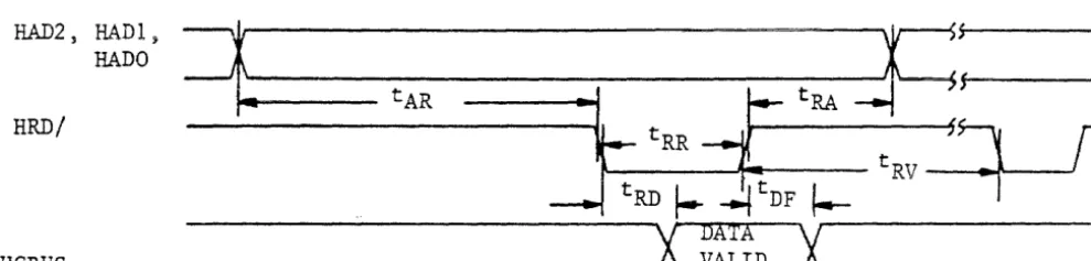
Data Transfer to or from the Interface
All data is transferred to or from the Interface on the HeBUS lines
under the control of the host-generated HWR and HRD strobe lines.
Figures 3 and
4
show the register Read and Write AC characteristics.Commands and parameters are usually transferred to the Interface
through the use of programmed I/O. Under programmed I/O the host
processor is in direct control of the I/O operation.
Many of the commands also contain a data transfer phase which may
transfer large blocks of data. Some host interface designers may
elect to implement Direct Memory Access (DMA) for the data transfer
phase of the commands.
30011SA
[image:17.621.91.409.49.458.2]Figures 3, 4, and 5 are valid for SMART Interface command or data transfers using programmed I/O or nMA data transfers.
HAD2, HAD 1 7
HADO
RRD/
ReBUS
Symbol
tAR tRA tRR tRD tnF tRV
~~---tA-R---I~--t-R-R---C:---tM----~;f~---FRD
~ ~F ~
tRV
_~:t---...l\---.Jr
---X
MIA
X~---_ X~---_ X~---_ X~---_ X~---_ X~---_ X~---_ X~---_ X~---_ X~---_ X~---_ X~---_ X~---_ X~---_ X~---_ X~---_ ---i VALID ... _ _ _ _ _ _ _ _ _ _
Parameter Min Max Units
Address stable before RD 60 ns
Address hold time for RD 30 ns
RD pulse width 250 ns
Data delay from RD 120 ns
RD to Bus Tristate condition 40 ns
RD recovery time 250 ns
Figure 3 - SMART Register Read AC Characteristics
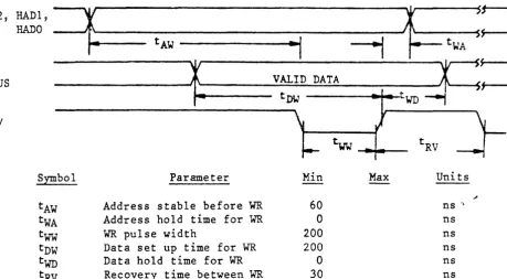
[image:18.623.65.560.75.455.2] [image:18.623.73.568.118.236.2]HAD 2 , HADl,
~
HAD 0
tAW
~I
--1
ReBUS
~
VALID DATAtDW
.
'.
HWR/
\
v I{___ tww
S~bol Parameter Min Max
tAW Addr~ss stable before WR 60
tWA Address hold time for WR 30
tww
'W"R pulse width 250tnw Data set up time for WR 60
twn Data hold time for WR 30
[image:19.621.49.565.60.637.2]tRV Recovery time between WR 250
Figure
4 -
SMART Register Write AC CharacteristicsDTREQ/
ffilR/ or HRD/
Symbol Parameter Min Max
tLR Date Transfer Request 0
HWR/ or HRD/
tRL Data Transfer Release 200
tRW HWR/ or HRD/ pulse width 250
tRV Recovery Time between pulses 250
Figure 5 - SMART Data Request AC Characteristics
14
~tWA
~:-twn
F
tRV
Units
ns ns ns ns ns ns
Units
ns ns ns
30011SA
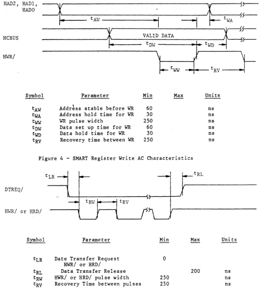
-The SMART-E bus timing is compatible with the SMART timing. The follow differences apply to the SMART-E:
1. There is no Data hold time for write (t . = WCl 0' / .
2. If jumper WI is in the B position the data transfer request
(DTREQ) line will become active for each data request and inactive when the data is transmitted/received.
Figures 6, 7, 8, 9, and 10 are valid for SMART-E Interface command or data transfers using programmed I/O or DMA data transfers.
The SMART-E supports buffered and direct mode data transferred. If
jumper WI is in the B-C position and the SMART-E Mode Byte is
initialized with bit
4
set, the SMART-E is placed in Direct Transfermode (See Mode Byte discussion in Section V.A.). Under direct
transfer mode the disc data is passed through to the host without going into the Interface buffer. Direct Mode requires a host bus interface that is,capable of transmitting and receiving the data at disc speed.
HAD2 s
~~"vl,
=1
W
~t--~~~
---~----~/~tWA
Sr--tAW
---·~~I
I
~
RCBUS
RWR/
r
VALID DATAh
---'~---.;..;;t..;;;;;DW;;.;;;...;;.::~~~::::;.:I:.:-tWD--...,- 1
-Symbol
tAW tWA
tww
tDW
twn
tRV
Parameter
Address stable before WR
Address hold time for WR
WR pulse width
Data set up time for WR
Data hold time for WR
Recovery time between WR
~
Min Max
60
0 200 200 0 30
Figure 6 - SMART-E Register Write AC Characteristics
15
tRV
Units
---~
ns " ns ns ns ns ns
[image:20.615.69.529.320.573.2]DTREQ/
HWR/ or HRD/
Symbol Parameter
tLR Data Transfer Request to
HWR/ or HAOI
tRL Data Transfer Release tRW HWR/ or HRD/ pulse width tRV Recovery Time between pulses
Min
0
200 200
Max Uni ts
ns
o
ns [image:21.617.33.544.60.498.2] [image:21.617.37.532.345.602.2]ns ns
Figure 7 - SMART-E Data Request AC Characteristics (Jumper WI in A to B position)
HAD2,
HRD/
HeBUS
HAD 1 , HAD 0
=t
tARtRR
-1[
'+-r
tRD
I"-~F
I--
tRV---,X
DATAX~---_ X~---_ X~---_ X~---_ X~---_ X~---_ X~---_ X~---_ X~---_ X~---_ X~---_ X~---_ X~---_ X~---_ X~---_ X~---_ --' VALID '-_ _ _ _ _ _ _ _ _ _
,;
Symbol Parameter Min Max Units
tAR Address stable before RD 60 ns tRA Address hold time for RD 0 ns
tRR RD pulse width 200 ns
tRD Data delay from RD 120 ns
tDF RD to Bus Tristate condition 40 ns
tRV RD recovery time 30 ns
Figure 8 - SMART-E Register Read AC Characteristics
BUSREQ/
DTREQ/
.\~-~-~~-Y
~.
tDRQ tDCY - - - - -....
J.----..
tDRL ..I
l
/
tDRP HHR/ OR HRD/
Symbol Parameter Min Max Units
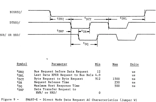
[image:22.612.41.578.73.425.2]tDRQ tDRL tDCY tDR tDQ tDRP
Figure 9
-Bus Request before Data Request 12
Last Data XFER Request to Bus Rels 4.0 Byte Request to Byte Request
Request Release Time
Maxi~um Host Response Time Data Transfer Request to
HWR/
or HRD/912
a
1500
250 500
us us ns ns ns
SMART-E - Direct Mode Data Request AC Characteristics (Jumper WI in the B to C position)
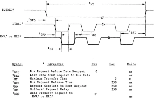
BUSREQ/
.tBRQ
DTREQ/
-HWR/ or HRD/
Symbol Parameter Min Max Units
tBRQ Bus Request before Data Request 0 ns
tBRL Last Data XFER Request to Bus Rels us
tMT Maximum Transfer Time 3 s
tBRL Bus Request Release Time 250 ns
tBQ Request Complete to Next Request 250 ns
tBR Buffered Request Delay 250 ns
tDRP Data Transfer Request to 0
HWR/ or HRD/ ns
Figure 10 - SMART-E - Buffered Mode Data Request AC Characteristics (Jumper
WI in the B to C position)
300115A
[image:23.621.42.575.52.399.2]IV. FUNCTIONAL INTERFACE
A. Command Initiation
Commands and data are transferred across an 8-bit bidirectional bus
under control of host-generated HRD and HWR strobes. Registers
within the controller are selected by decoding three address lines:
HAD 2 , HAD I , and HADO. Information is transferred over the TRISTATE
bidirectional bus (RCBUS7 to HCBUSO). An active HRD signal places
the bus in the transmit mode; an active HWR signal places the bus in
the receive mode.
If the S~~RT-E is used with Jumper W7 in the B to C position the
Interface will generate or check even parity on the HCBUS7 to HCBUSO lines (HCBUS8 is the bus parity line). Parity is valid for all data transfer across the RCBUS except for host reads of the Interface
Status Register. The Interface Status Register includes hardware
generated signals that change asynchronous to HRD or HWR.
Table 5 shows the'addressing required to select each of the registers.
A
command is issued whenever the host loads the command register.Therefore, all the appropriate parameter registers must be loaded prior to loading the Command Registerc When the Command Register is loaded, the Busy bit in the Interface Status Register will be set and will remain set until the command is validated and the parameter registers are copied into the Interface local memory.
After the SMART Interface has accepted the command the Busy bit is
cleared. The Busy bit is cleared before the command is completed so
that the host may issue overlapped seeks or other overlapped commands to other drives.
When using the SMART Interface the Command Reject will be set if any of the following errors occur:
1. The drive number is invalid.
2. The selected drive already has a command in process.
3. The command was written to the command register while Busy was
set.
The Host Interrupt Request (HIR) is not activated if the command is rejected during the initial command validation phase of the SMART.
~~en using the SMART-E Interface the following errors will cause the SMART-E to abort all commands in process and set Host Interrupt Request (HIR) with the appropriate transaction status:
1. The drive number is invalid.
2. The selected drive already has a command in process.
3. The command was written to the command register while Busy was
set.
4. A bus parity error was detected.
300115A
After a command has been completed, a command completion is indicated through the Command Completion Request bit in the Interface Status Register (see Table 6).
When the Command Completion Request Bit is set, the Host Interrupt Request line (HIR) is activated.
The Command Completion Request and the Host Interrupt Request are cleared by issuing the Completion Acknowledge command (see Command Descriptions).
Table 4 is a summary of the commands that are supported by the Interface. These commands are discussed in Section V of this specification.
Command Code (Hex)
# if 41 II # # :fF II # :fF # iff # # # # II # 00 03 04 05 06 07 08 09 40 44 48 51 41 52 42 53 43 55 45 56 46 57 47 59 49
5A
4ATABLE 4 - Command Summary
Command Name
Completion Acknowledge Read Buffer
Write Buffer
Read Internal Status Read Drive Status Software Reset
Specify SMART Mode (SMART-E Only) Read SMART Mode
Drive Restore Verify Data Verify ID
Seek - Retry Enabled Seek - Retry Disabled Write Data - Retry Enabled Write Data - Retry Disabled Read Data - Retry Enabled Read Data - Retry Disabled Write ID - Retry Enabled Write ID - Retry Disabled Read ID - Retry Enabled Read ID - Retry Disabled
Read ID Immediate - Retry Enabled Read ID Immediate - Retry Disabled Read Skip Defect Field - Retry Enabled Read Skip Defect Field - Retry Disabled Write Skip Defect Field - Retry Enabled Write Skip Defect Field - Retry Disabled
30011SA
Command Code (Hex) 0 ' 0.1 82 83 85 86
AD
Al A2 A3 A4 AS A6 A8IF A9
# AA
AB AC An\ AE EO El
Cetmnand Name
Sequence Down
Sequence Up Wait -Sequence Up - Return Read Drive Parameters Read Drive Type
Format Disc Format Cylinder Format Track Verify Disc Verify Cylinder Verify Track
Read Defect Directory
Format Disc With Defect Mapping Specify Bad Track
Specify Bad Sector Write Disc - Full Track Write Cylinder - Full Track Write Full Track
Write Defect Directory
Transfer Parameter to Result ID Buffer Transfer Test
In the SMART-E Interface, commands marked with '#' will accept a logical address if the Interface is in Logical Sector Mode.
B. User-Accessible Registers
Table 5 lists the registers that are directly accessible to the host, and shows the address and control signal values needed to access each register. Table 6 defines the bits of the Interface Status
Register. Tables
5,
7, and 8 and the accompanying text define thefields of the Transaction Status (Result 0) Register. The text
following Table 8 discusses the remaining parameter registers and result registers.
TABLE 5 - Control Register Assignment
HAD2 HAD 1 HADD HRD HWR Register
0 0 0 1 0 Interface Status
0 0 1 1 0 Read Disc Data
0 1 0 1 0 Result 0
(Trans-action Status)
0 1 1 1 0 Result 1
1 0 0 1 0 Result 2
1 0 1 1 0 Result 3
1 1 0 1 0 Result 4
1 1 1 1 0 Result 5
0 0 0 0 1 Command
0 0 1 0 1 Write Disc Data
0 1 0 0 1 Parameter 0
0 1 1 0 1 Parameter 1
1 0 0 0 1 Parameter 2
1 0 1 0 1 Parameter 3
1 1 0 0 1 Parameter 4
1 1 1 0 1 Parameter 5
3001lSA
[image:26.617.155.441.62.324.2] [image:26.617.84.477.75.469.2] [image:26.617.132.501.503.764.2]Bit
7 (MSB)
6
5
4
3
2
1
TABLE 6 - Interface Status Register
Name
Command Reject
Command Completion Request
Special Completion
Interface Busy
Data Transfer Request
Read/Write Request
22
Description
An undefined or invalid command was received.
The Interface has
performed the requested function and the
transaction status is available in the Transaction Status Register.
The Special Completion bit is set (along with
eS6) if the completion is for a command that may be overlapped with a
drive command. Commands
that set the Special Completion bit are identified in the command descriptions.
Reserved
The Interface has received a command and is busy parsing the requested command.
This bit indicates the
s ta te of the DTREQ/ ~
interface line.
If this bit is active and the Data Transfer Request line is active, a read data operation is
required. If this bit
is not active and the Data Transfer Request
line is active, a write data operation is
required. This high
active bit indicates the state of the HREAD
interface line.
[image:27.618.114.548.58.692.2]TABLE 6 - Interface Status Register (Cont'd)
Bit Name
o
(LSB) Data Bus EnableTransaction Status (Result Register 0)
Description
The Data Bus Enable bit indicates that the Interface has
successfully completed its self test. This high active bit
indicates the state of the DBUSENA interface line.
The Transaction Status Register (Result 0) indicates the result of an
Interface command! The format of the Transaction Status Register is
shown in Table 7. When the Interface Status Register indicates that a Command Completion Request is pending, the host processor should read the Transaction Status Register to determine the outcome of the
command. After the Host has read the Result Register the Host should
issue the Completion Acknowledge command so that the Interface may post the next command completion.
The four major completion types are listed below:
1. Good Completion - 0
This type of completion indicates that the command was
successfully completed. Some steps may have been retried.
The following codes are generated if the automatic retry logic is unable to recover from the error.
2. System Error - 1
These errors result from a system, controller or drive problem.
3. Operator Intervention - 2
These errors require human intervention for recovery.
4. Command or Drive Error - 3
Command errors are usually due to a user program error.
Table 8 provides more detailed information about completion types and completion codes.
300115A
TABLE 7 - Transaction Status Register
Bit Number:
Bit Designation:
B1&.. ·~
Dl, DO
Tl, TO
CC3, CC2,
cel,
CCO7 6 5
Dl DO Tl
Name
Drive
Completion Type
Completion Code
24 4
TO
3 2 1 0
CC3 CC2 CCI CCO
Description
This field indicates to which drive the transaction status applies.
This field defines the four major
classes of completion. See Table
8.
The completion codes provide a detailed definition of the command
termination. See Table 8.
Completion Type
(Bits 5-4)
o
,
..L
2
3
TABLE 8 - Completion Code Summary
Completion Code
(Bits 3-0)
0 1 2 3 0 1 2 3 4 5 6 7 8 9 .. f t B C D 0 1 2 3 4 5 6 7 0 1 2 3 4 5 6 7 8 9 A B 25 Definition
No Retries Performed Motion Retry Performed Data Retry Performed ECC Correction Performed (SMART-E Only)
Late Data Transfer CRC Error (SMART) or Uncorrectable ECC Error
(SMART-E)
Seek Fault - Drive Reported Drive Fault
Not Used
Seek Fault - Cylinder Mismatch Initialization Complete
Stack Error Hardware Trap
Read Loss Synchronization
RAM
FailureID Buffer Failure
Bus Parity Error (SMART-E Only)
PROM Checksum Error (SMART-E Only)
Drive Not Ready Write Protect
Drive Not Present Sector Size Invalid Alternate Area Overflow Defect Directory Full End of Defect Directory Defect Directory Not Present
Sector Not Found Command Reject
Drive Busy Command Time-Out Data Transfer Time-Out Illegal Cylinder or Head Address
Invalid Drive Number Sector Number Invalid
Command Already In Progress Command Double Write
Drive Command Reject
Multisector Operation Error Invalid Interleave Factor (SMART-E Only)
[image:30.617.77.538.72.728.2]The following section provides a summary of the completion codes and a detailed description of each code.
Transaction Status
(Bits 5-0) Definition
00 No Retries Required
This status code indicates that the command completed successfully without any retries.
01 Motion Retries Performed
02
03
10
11
12
13
15
This status code indicates that an automatic retry was used to recover from an error and then
the command completed successfully.
Data Retries Performed
This status code indicates that a data error occurred but an automatic retry recovered from the error and completed the command successfully.
ECC Correction Performed (SMART-E Only)
This status code indicates that a hard read error occurred but the ECC logic was able to correct
the bits in error.
Late Data Transfer (SMART-E Only)
This error may occur when operating the SMART-E
in direct mode. A late data transfer will occur
if the host interface does not read/write data fast enough to match the disc transfer rate.
CRC Error (SMART) or Uncorrectable ECC Error (SMART-E) This status code indicates that a eRC error was detected on a read operation (SMART), or that an uncorrectable ECC error was detected (SMART-E).
Seek Fault - Drive Reported
This status code indicates that a seek was
attempted and the seek failed. The seek error
was indicated in the disc drive status.
Drive Fault
This status code indicates that the operation was terminated due to one of the conditions in Table
9.
Seek Fault - Cylinder Mismatch
This status code indicates that a seek was performed and completed by the drive, but a comparison of the drive current cylinder registers with the intended address indicated
that the wrong cylinder was selected.
Transaction Status
(Bits 5-0) Definition
16 Initialization Complete
17
, Q
.A. V
19
lA
IB
\
This status code indicates that the Interface has successfully completed a restart operation (power up or interface line reset). This completion provides the following Result Register values:
Result 1
=
AAResult 2
=
55
Result 3
=
FO
Result 4
=
OF
Result
5
=
00This completion does not generate an interrupt request, but it must be acknowledged by a Completion Acknowledge command.
Stack Error
This status code indicates that a hardware
failure occurred that resulted in an instruction fetch from a nonexistent program memory location.
Hardware Trap
This status code indicates that an unexpected processor interrupt (trap) occurred.
Read Loss Synchronization
This status code indicates that read operation
was terminated before the expected number of data
bytes were read from the disc.
RAM
FailureThis status code indicates that the micro-diagnostics have detected a bad RAM location.
The result registers have the following meanings:
Result 1 = Expected Data
Result 2
=
Received DataResult 3
=
Memory Address MSBResult 4
=
Memory Address LSBID Buffer Failure
This status code indicates that the micro-diagnostics have detected an error in the ID buffer.
The result registers have the following meanings:
Result 1 = Expected Data
Result 2
=
Received DataResult 3 = Buffer Location
Transaction Status
(Bits 5-0) Definition
lC Bus Parity Error (SMART-E Only)
This status code indicates that the SMART-E Interface has detected a parity error (the
HCBUS7-HCBUSO and HCBUS8 should have even parity) on the host interface. This applies to both commands and data.
ID PROM Checksum Error (SMART-E Only)
20
21
22
23
24
25
This status code indicates that the diagnostics have detected a program ROM failure.
Result register 1 contains the PROM number in error:
Result 1=0 Result 1=1 Result 1=2
Drive Not Ready
PROM Location 22A PROM Location 22B PROM Location 22C
This status code indicates that the Interface attempted to sequence up the drive and the drive did not indicate that it was ready within the expected period of time.
Write Protect
This status code indicates that a write operation was attempted on a write-protected drive.
Drive Not Present
The drive specified is not connected or not powered up.
Sector Size Invalid
The sector switches on the drive are set incorrectly.
Alternate Area Overflow
This status code indicates that there are more defective sectors or tracks than there are spare sectors or tracks on the disc.
Defect Directory Full
The defect mapping logic was unable to expand the size of the defect directory because all
available space was in use.
300115A
Transaction Status
(Bits 5-0) Definition
26 End of Defect Directory
If the disc has been formatted with defect
mapping enabled, there will be a Defect Directory
located in the user alternate area. The
directory is a linked list of 128 byte records . that are numbered through N-l where N is the
number of 128 byte records in the directory. This error code will be received if a Read or Write Defect Directory command is issued that has
specified a record number greater than N.
27 Defect Directory Not Present
This error code indicates that a Read Defect Directory command was issued to a drive that was
formatted without defect mapping.
30 Se~tor Not Found
This code indicates that the specified logical sector could not be located.
31 Command Reject
The received command 1S not supported by the
Interface.
32 Drive Busy Command Time-out
33
34
35
36
37
This status code indicates that the Interface issued a command to the drive and the drive did not properly complete the command.
Data Transfer Timeout
This status code indicates that the Interface requested a data transfer to the host and the transfer was not completed within 3 seconds.
Illegal Cylinder or Head Address
This code indicates that a head number or cylinder number greater than the maximum supported was specified as a parameter.
Invalid Drive Number
This code indicates that a drive number greater than three was specified as a parameter.
Sector Number Invalid
This code indicates that a physical operation (as distinguished from a logical operation) failed to find the specified sector.
Command Already In Progress
This code indicates that the specified drive already had a command in progress.
30011SA
38
39
3A
3B
Command Double Write
This error occurs if the host writes to the
command or parameter registers when the Interface Busy bit is set.
Drive Command Reject
This error code indicates either a Interface or drive hardware failure.
Multisector Operation Error
This error code indicates that a read or write data command was issued with a multisector count equal to zero or greater than 7F HEX.
Invalid Interleave Factor (SMART-E Only) This error code indicates that a command requiring an interleave factor was issued and
that the interleave factor was incorrect. The
discussion on interleaving describes the use of the interleave factor.
TABLE 9 - Drive Fault Conditions
1. WRITE GATE without write current at the head.
2. Write current at the head without WRITE GATE.
3. WRITE GATE without READY.
4. More than one head selected.
5. No transitions during·write (MFM format).
6. WRITE GATE with WRITE PROTECT.
7. WRITE GATE between INDEX and the first SECTOR MARK (when the Skip Defect Record is write protected).
There is a common format for both parameter and result registers used in most commands.
Listed below are some commonly occurring formats for Parameter and Result
Registers 0 to 4. These are used in many (though not all) commands. For
purposes of illustration, physical addresses are shown for the contents of Parameter and Result Registers 1 to 3. When the SMART Interface is used, addresses on the disc must be specified by the host system as physical
addresses. When the SK~RT-E Interface is used, the host system may
specify either physical or logical addresses, in accordance with Bit 6 in the Mode Register.· See the section on Disk Addressing Methods for more details.
[image:35.620.74.493.25.506.2]Parameter Register 0
Bit Number
Bit Designation
where:
Dl
o
o
1 1Parameter Register 1
Bit Number
Bit Designation
DO
o
1
o
1
i
o
i
o
6
o
6
H2
5
o
5
HI
4o
Drive 0
Drive I
Drive 2
Drive 3
4
HO
3 2 1
o
o
o
Dl DO3 2 1
o
CII CIO C9 C8
where: H2, HI, HO define the target head address and CII, ClO, C9,
C8 are the upper binary bits of the target cylinder
address. Both heads and cylinders are numbered
consecutively, starting with O.
Parameter Register 2
Bit Number 7 6 5 4 3 2 1
o
Bit Designation C7 C6 C5 C4 C3 C2 Cl
co
where: C7 through CO are the 8 least significant bits of the
target cylinder address. Cylinders are numbered
consecutively, starting with cylinder O.
Parameter Register 3
Bit Number 7 6 5 4 3 2 1
o
Bit Designation
o
S6 S5 S4 S3 S2 Sl SOwhere: S6 through SO are the 7 binary bits defining the target
sector. Within a given track, sectors are numbered consecutively, starting with sector O.
300115A
P~rameter Register 4
Bit Number 7 6 5 4 3 2 I
o
Bit Designation
o
M6 M5 M4 M3 M2MI
MOwhere: M6 through MO are the 7 binary bits defining the total
number of consecutive logical sectors to be read or
written. The valid range is from 1 to 7F (HEX) sectors.
The formats of the most cammon result registers are as follows:
Result Register 0
See Table 7 for the Result Register 0 definition.
Result Register I
Bit Number 7 6 5 4 3 2 I
o
Bit Designation
o
H2 HI HO CII CIO C9 C8where: H2, Hl, HO define the current selected head address and
CII,
CIO,C9,
are the upper binary bits of the currentcylinder address. Both heads and cylinders are numbered
consecutively, starting with
O.
Result Register 2
Bit Number 7 6 5 4 3 2 1
o
Bit Designation C7 C6 C5 C4 C3 C2 CI
co
where: C7 through CO are the 8 least significant bits of the
current cylinder address. Cylinders are numbered
consecutively, starting with cylinder O.
Result Register 3
Bit Number 7 6 5 4 3 2 1
o
Bit Designation
o
S6 S5 S4 S3 S2 SI SOwhere: S6 through SO define the number of the last sector
accessed. Within a given track, sectors are numbered consecutively, starting with sector O.
Result Register 4
Bit Number 7 6 5 4 3 2 1
o
Bit Designation
o
M6 M5M4
M3 M2MI
MOwhere: M6 through MO indicate the residual sector count (non-zero
if an unrecoverable error occurred).
300115A
c.
Disk Addressing MethodsThere are three types of addressing used to identify locations on the
disc (s ).;
Absolute Addressing Physical Addressing Logical Addressing
Absolute addressing identifies a location by specifying a head
address, cylinder address, and sector address. The head addresses
run from 0 to N-1, where N is the number of read/write heads on the
drive; each possible value represents a particular heads The
cylinder addresses run from 0 to T-1, where T is the number of tracks per disc surface; each possible value represents a particular
cylinder, with 0 at the outer edge of the usable disc surface. The
sector addresses run from 0 to S-1, where S is the number of sectors per track; each possible value represents a definite sector, and the
-sectors are numbered consecutively. The sector addresses increase as
the disc rotates; 'Sector 0 is the first sector after the skip defect field.
Physical addressing uses the same format (head, cylinder, sector) as absolute addressing, but the physical address of a given sector may
be different from that sector's absolute address; There are two
factors leading to such differences -- defect mapping and
interleaving. Defect mapping is the process through· which a bad sector or track is identified, with an alternate assigned and used in its place. The defect directory is a list of these defective
regions, with the corresponding alternate sectors or tracks also listed. When the Interface is processing a command which involves a read or write operation on a defective sector or track, the Interface automatically performs that operation on the corresponding alternate
track. Except for the additional time required, this substitution 1S
entirely transparent to the host system. The details of defect
mapping are discussed in Section IV.E. of this specification. Interleaving (available only with the SMART-E interface) is a
technique which may be used to enhance system performance under 'some
conditions. It is a mapping performed on the sectors within each
track. The user specifies an interleave factor (equal to the number
of unacc€ssad absolute sectors between successively accessed physical
sectors). For example, an interleave factor of 0 causes successive absolute sector addresses to be accessed, while an interleave factor
of 1 causes every second absolute sector address to be accessed. The
~MA'Q'T'_l4' T,..,+-o .. 4= ... o .... ..". ... 4=""' ... '" +-h ... .: .... +-O ... 'O .. ~T.: .... ,... .: ... .., ... "' .... +-h ... .:,..
IW'.A.~ . . . .i.\..~. "Q."""~ r''t;;. .. ..L.V.l.U.~ ... J.~ . . .L..&. ... ~.&.. .... ~Q.y..LJ.J,O ... ,£. Q Ui.Q.",J.""'~J.. I..LJ.Q.&,.. ..&..-::J
transparent to the host system. More details on interleaving are given in the next section of this specification.
Logical addressing (supported only by the SMART-E Interface) allows the user to relate to the disc storage space as a list of sectors,
numbered from 0 to the total usable storage capacity of the dri~e.
The host system loads Parameter Registers 1, 2, and 3 with the
logical sector address (Parameter Register 1 is the most significant
300115A
byte, and Parameter Register 3 is the least significant byte). The SMART-E Interface translates this into a physical sector address, and
then proceeds in the manner described below. Defect mapping and
interleaving (if required) are performed as part of the conversion between physical and absolute addressing. When the SMART-E reports results to the host system, it translates the physical address back
into a logical address, before placing it in Result Registers 1, 2,
and 3.
D. INTERLEAVING
Interleaving is a capability of the SMART-E Interface. It provides a
means by which the host system may regulate the rate at which data
passes between the host and the disc. Interleaving occurs within
each track, and affects the sequence in which sectors are accessed during multi-sector operations.
The user controls the interleaving function by specifying an
interleave factor. This is sent to the SMART-E interface as
Parameter 3, priof to issuing one of the following commands:
Format Disc with Defect Mapping Format Disc
Format Cylinder Format Track
In the absence of interleavin~ the sectors are accessed sequentially;
successive physical or logical sectors are also successive absolute
sectors. If interleaving is not desired an interleave factor of
°
should be specified by the host. If interleaving is desired, the
host may specify some other value. The SMART Interface does not
support interleaving. An interleave value of 0 should always be specified when using the SMART Interface.
The value specified as the interleave factor is the number of unaccessed absolute sectors that lie between successive physical sectors. For example, if the user specifies an interleave factor of
3, then phys ical sectors 0, 1, 2, ••• wi 11 correspond to abs 01 ute;
sectors 0, 4, 8, •••
During the formatting process, the SMART-E Interface writes a
physical address of
°
into the ID field of the first absolute sector,then skips k absolute sectors (where k is the interleave factor), then writes physical address 1 into the ID field of the next absolute
sector, and so on. The process continues until physical addresses
have been assigned to all absolute sectors on the track(s) to be
formatted. It is important to note that some interleave factors will
not allow an assignment that results in k absolute sectors between
some physical sectors. If during the setup of the ID fields the
SMART-E detects that the next sector is already used the next available sector will be assigned instead (see example).
30011SA
Example: Interleave factor/sector assignment
per track
Interleave factor
=
1Absolute Sector Number: Physical Sector Number:
Sectors per track
=
6Interleave factor
=
,
.LAbsolute Sector Number: Physical Sector Number:
0 0 0 0 1 3 1 3 2 1 2 1 3 4 3 4 4 2 4 2 5 5
This example demonstrates a case where a sector per track/interleave factor combination does not result in proper sector spacing.
Physical sector 3 is actually two sectors from physical sector 2.
The interleave factor may have any value from 0 up to half the number
of sectors per track.
If the host system must implement custom interleave formats not
supported by the standard algorithum, the user may specify the factor table directly.
When an interleave factor of OFO HEX is specified the Interface will
perform a data request for N bytes of data (where N is the number of
sectors per track). The N bytes of data specify the physical sector
numbers in absolute sector sequence. The first byte of data will be
absolute sector zeros physical address, the second byte of data will be absolute sector one's sector address, etc.
The interleave factor is specified at the time of formatting, and can not be changed dynamically during normal operation.
In choosing an interleave factor the user should consider the following things concerning his system:
Data transfer time across the host interface. Host processing time for this data.
Number of sectors to be transferred on a single
Table 10 displays the basic timing parameters of the interface
required to compute interleave factors.
Table 10 - SMART/SMART-E Command Delays
OPERATION
Completion ACK (Issue command to busy Clear) Command Start (Issue command to busy Clear) Initiate/Terminate Read/Write Data command
NOTES: 1. Aii times are approximate
SMART
80 us
16D us
2 ms
SMART-E
30 us
110 us
1 ms
2. All times assume non-overlapped command operation
300115A
[image:40.623.123.402.60.200.2]E: DEFECT MAPPING
During the operation of the Format Disc with Defect Mapping Enabled command the Interface may encounter a defective sector on a track. The defect mapping capabilities of the Interface allow it to assign
alternate areas for the defective areas. The Interface creates a
defect directory described in the next section, during the format
operation. Each drive has an area reserved for alternate sectors.
1. Defect Map Format
If the disc is formatted with defect mapping enabled the defect directory is created on the first good track of the alternate
sector/track area. (See Tables 11 through 14.)
The Defect Map is a linked list of 128 byte records. Locations
1 and 2 of each record contain the address of the track that
contains the next directory record. If a record is the last
record in the directory, the link address will be zero.
\
TABLE 11 - Defect Directory Format
Location (HEX)
o
01, 02 03 04, 05
06 10-7F
Description
Configuration Level Next entry link address
Interleave Factor (SMART-E Only)
Interleave Factor Table Address (SMART-E Only)
Configuration Data (to be defined) Defect Directory Entries (see Table 12)
TABLE 12 - Defect Directory Entry Format
Location
o
1 2 3 4 5 DescriptionDefect Cylinder Address LSB Defect Head/Cylinder Address MSB Defect Physical Sector Address
(If FF HEX
=
End of directory;if FE HEX = defective track.)
Alternate Cylinder Address LSB Alternate Head/Cylinder Address MSB Alternate Physical Sector Address
TABLE 13 - Alternate Areas <Cylinders) by Drive Type
Drive Type
3350
6650/15450 3450
7050 1070
User Cylinder
0-554 0-1107 0-514 0-1038 0-184 36
[image:41.613.88.495.117.590.2]There are as many defect directory entries created as are required. The Format Disc with Defect Mapping command proceeds as follows:
a. The entire disc is formatted including the alternate areas
defined in Table 13.
b. The skip defect records are read and the bad tracks and sectors
are flagged by reformatting t