Quantization of Three-Bit Logic for LDPC
Decoding
Raymond Moberly and Michael E. O'Sullivan
Abstract— This paper presents two related three-bit quantiza-tions for sum-product algorithm LDPC decoding that are suitable for programmable logic. The key aspect of our decoder design is the combining of the parity-check and variable node update steps into a single computation. The performance and the hardware requirements for an FPGA implementation are considered and compared to the work of Planjery et al.
I. INTRODUCTION
Low Density Parity Check (LDPC) codes are well suited for error-correction applications. However, the challenge is to nd strategies that will enable ef cient implementations while ensuring good performance. Iterative decoder designs using a small number of quantization bits appear in the works of T. Zhang and Parhi[1], and Planjery et al[2], and Z. Zhang et al[3]. Each team has devised a design suitable for digital logic implementation.
In this paper we present quantizations for a sum-product algorithm LDPC decoder using the receiver sampling reso-lution available on a Gaussian channel. We examine decoder performance of various three-bit quantizations, nding that the best choice of quantization changes as the channel conditions change. Our design combines the parity check and variable-node update steps into a single computation. This paper presents synthesis results showing the latency and footprint of the key computational component of our decoder design.
Our experiments are with a rate-1
2length 1162 binary LDPC code; it is from a family of codes that our research group has generated using permutation matrices[4][5]. This methodology permits the construction of codes of large girth. The cyclic permutation structure is known to have ef cient hardware implementations[6][7].
II. SCOPE
The Sum Product Algorithm (SPA) was simulated on a computer cluster, using look-up tables based upon three-bit quantization, for 10 iterations. Our quantization, with 10 iterations, surpasses the performance of Planjery et al with 100 iterations. We determine the per-iteration computational latency and evaluate trade-offs between iterations and compu-tation per-iteration, which contribute to total latency and gain.
Manuscript received July 21, 2011; revised August 16, 2011.
This research was supported in part by NSF grants CCF 0635382 and CHE 0216563. FPGA hardware and development tools were provided by the Altera Corporation.
R. Moberly is with the Computational Science Program, San Diego State University, San Diego, CA 92182, USA email: [email protected]
M. E. O'Sullivan is with the Mathematics Department, San Diego State University, San Diego, CA 92182, USA email: [email protected]
We select these as the comparison criteria in our conclusion and we discuss other potential criteria; in an engineering application, decoder design could be optimized for throughput or power consumption.
A. FPGA Implementation
The Field Programmable Gate Array (FPGA) offers a very rapid pathway to concept development; it is also well-suited to computation with non-standard precision and variable data types that are not available in microprocessors. The Applica-tion Speci c Integrated Circuit (ASIC) also offers customized precision, but there is a high development cost. In contrast to ASIC development, FPGA development is low-cost, easily debugged, and correctable. When implementing the sum-product algorithm in an FPGA, the designer has a choice of precision and quantization; precision can be increased at the cost of computational speed. Size, power, and latency are important engineering factors in communication systems.
Reducing precision reduces the coding gain but accelerates the computation. An FPGA solution [1] in the literature achieved LDPC decoding using operands with just 5-bits. Our own prior research [8] explored tradeoffs between the number of bits of precision and the number of decoding iterations. Synthesis results, such as those presented in our present paper, help to explore the capability and performance of an FPGA-based decoder.
The LDPC decoder for a regular code has a very repetitive structure, performing identical operations on each bit of the received code word. Our analysis, implementation, and syn-thesis presents the computation for a single code symbol. The length 1162 LDPC code that we tested our decoder with is a rate-1
2 (6,3)-regular code. Each variable node outputs three updated messages; we implemented the logic of just one of these output messages in order to determine the latency, and then implemented all three outputs to observe the consequent speed and size. Logic synthesis can seek to maximize speed, or minimize chip area, or optimize some combined weighted function of speed and chip area.
The Altera DE2 development board was selected for this work and requested from and provided by the Altera Corpo-ration as a university research grant. The FPGA on the DE2 board is the Cyclone II EP2C35F672C6N, it has a substantial number of programmable logic elements (33,216).
B. Formulations of the Iterative Algorithm
µ0,µ1 δµ ρµ λµ
ν0,ν1 δν ρν λν
Levine
Levine
MacKay
MacKay
Jimenez
Jimenez
Fig. 1. Iterative SPA Formulations in the Literature
µ0,µ1 δµ ρµ λµ
ν0,ν1 δν ρν λν
Moberly / O’Sullivan
Moberly / O’Sullivan
Fig. 2. Our published Formulation of the Sum-Product Algorithm
cycling through probability representations, where the variable and parity check messages can be expressed in terms of probabilities, differences p= P(0) P(1), ratios p=
P(0)
P(1), or log-likelihood ratios p = log p. We compared various formulations of the SPA[10][11][12][13] which were mathematically equivalent but computationally different. One of the conclusions of that paper - formulations which represent probabilities as differences ( p) or as log-likelihood ratios
(LLR) offered signi cant computational advantages. These resulted in fewer CPU instructions. Transforming multiplica-tion operamultiplica-tions into addimultiplica-tion operamultiplica-tions in the log domain increases performance on computer processors with arith-metic logic units that can perform addition more rapidly than multiplication[14][15][16][17][18]. The advantage is de nitely signi cant when working with 32-bit and 64-bit variables; but what if there are only a few bits of precision in use? For limited precision, the difference between O(n bits)addition
versus O(n2 bits)multiplication might not be signi cant. As Han and Sunwoo showed[19], the LLR calculations involve one particularly obstructive computation, an inverse hyperbolic tangent function; their limited precision computa-tion involves a table for this calculacomputa-tion. Zhang et al have also looked at xed-point LLR quantizations using 5, 6 and 7 bits[3]; in these implementations, the hyperbolic tangent func-tion is a substantial part of the design effort and computafunc-tional work.
The cycle for the formulation we introduced is shown in Figure 2. In this paper, instead of looking at the parity check and variable-node update as two separate actions, we will present the cycle as a single computation with one quantization applied per iteration.
C. Comparing BSC and AWGN
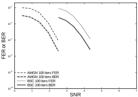
The Additive White Gaussian Noise (AWGN) channel and the Binary Symmetric Channel (BSC) both appear in simula-tion efforts as representatives of real-world channel condisimula-tions. This paper compares decoding results on a Gaussian channel
0 1 2 3 4 5 6 7
10-10 10-8 10-6 10-4 10-2 100
SNR
F
ER
o
r
BER
AWGN 100 iters FER AWGN 100 iters BER BSC 100 iters FER BSC 100 iters BER
Fig. 3. FER and BER for AWGN and BSC Channels
with competing published results that use the BSC. The equivalence computation is = 12 erfc(p2Eb
N0), where is the BSC bit crossover probability, and Eb
N0 is the signal to noise ratio (SNR) that characterizes a Gaussian channel. For decoders with oating-point belief propagation, there is an almost 2 dB difference in performance. Truncation to a hard decision at the receiver results in the 2 dB loss that differentiates the BSC and AWGN channels, as shown in gure 3. The difference is about the same whether the decoder is evaluated based upon bit error rate (BER) or frame error rate (FER).
Considering this loss, it seems a natural move to collect soft decisions at the receiver if the decoder is going to work with soft-information internally. Our decoder design assumes a soft-decision receiver with three bits of precision and our speci ed quantizations.
III. PLANJERY'SBEYONDBELIEFPROPAGATION We replicated the quantized three-bit algorithm speci ed in Planjery's paper[2]. We reproduced the 100 iteration results from their paper using several published codes (e.g. bench-marks) and ran simulations for our own code with both 10 and 100 iterations for a range of SNR values. These are shown in gure 4 (BER) and gure 5 (FER). Each graph shows the applicable reference curves from gure 3.
[image:2.612.319.556.54.221.2] [image:2.612.78.270.169.236.2]0 1 2 3 4 5 6 7 10-10
10-8 10-6 10-4 10-2 100
SNR
BER
Planjery as Published 10 iters Planjery as Published 100 iters Planjery Proprietary 100 iters
Fig. 4. BER for Published and Proprietary decoders of Planjery et al
0 1 2 3 4 5 6 7
10-10 10-8 10-6 10-4 10-2 100
SNR
F
ER
Planjery as Published 10 iters Planjery as Published 100 iters Planjery Proprietary 100 iters
Fig. 5. FER for Published and Proprietary decoders of Planjery et al
proprietary performance curves are repeated in the charts for our quantizations, gures 8 and 9, for comparison.
The Planjery et al three-bit algorithm begins with a single bit quantization (a hard decision) at the receiver. It performs another quantization at each parity check, and then quantizes again at each variable node update. Three-bit messages are used for the parity check operation inputs and outputs. Other algorithms in the literature quantize in a similar fashion, two quantizations per iteration, as illustrated in Figure 6.
A. Synthesis of the Planjery Vasic 3-bit Decoder
We implemented the three-bit logic of their parity checks and variable node update in Verilog HDL. The synthesis results, targeting our Cyclone II FPGA, were reported by the Altera Quartus II software.
The single bit computation used 138 logic elements and had a longest path delay of 20.489 nanoseconds. If we were to compute 1162 bits (the length of this LDPC code) simulta-neously, the footprint would expand to 160356 logic elements. If we were to compute, sequentially, the 100 iterations used in Planjery and Vasic's simulations, the decoding latency would
parity check
variable node update
i
j α
k
µjα(n-1)
µkα(n-1)
ναi(n)
i
ζ µiα(n)
ζ h
φ
g φ
α µhζ(n-1)
µgζ(n-1)
νζi(n)
µi(0 )
ναi(n)
whole iteration
A2Dj A2Dh A2Dg
A2Dk A2Di
1-bit hard decision 3-bit quantized 3-bit quantized 3-bit quantized
1-bit hard decision
Fig. 6. Quantization of the Variable Nodes and the Parity Computation
parity check
variable node update
i
j α
k
µjα(n-1)
µkα(n-1)
ναi(n)
i
ζ µiα(n)
ζ h
φ
g φ
α µhζ(n-1)
µgζ(n-1)
νζi(n)
µi(0 )
ναi(n)
whole iteration
A2Dj A2Dh A2Dg
A2Dk A2Di
3-bit soft decision
3-bit soft decision 3-bit quantized not explicitly quantized 3-bit quantized
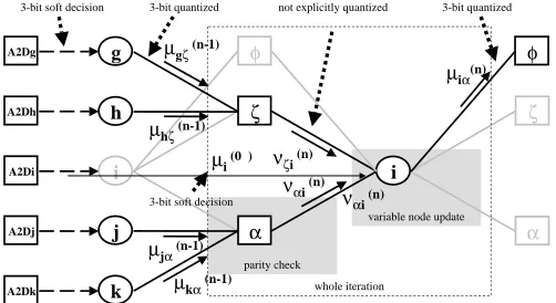
Fig. 7. Quantization of the Variable Nodes. One Quantization per Iteration
be multiplied to 2.0489 microseconds.
This synthesis result gives a baseline for the implementation cost of their published algorithm. Their second stage pro-prietary rule, giving them signi cant additional coding gain, increases the implementation cost by an amount unknown to us. The quantizations that we propose in the following sections require more logic elements, but our performance results show the bene ts of those additional implementation costs.
IV. OURWORK: ONECOMPUTATIONPERITERATION The SPA is typically described as two computational steps. If we consider the iteration to be a combined-step instead of the two separate steps, the formulation still has mathematical equivalence but the computation changes. Instead of applying quantization twice in an iteration, one quantization is applied. The intermediate quantization is not speci ed, but quantization is implied; that implied quantization is described later in the synthesis results subsection. Figure 7 illustrates the whole-iteration computation that we worked with.
A. Quantization Scales
[image:3.612.306.563.54.194.2] [image:3.612.59.303.56.218.2] [image:3.612.312.563.234.371.2] [image:3.612.58.293.256.422.2]in LDPC decoding in our previous effort. A quantization scheme using the sigmoid function, S(x) = 1
1+e x, was
among those that we used to determine the discrete scale values[8]. In this paper we present two related three-bit quan-tizations, based upon sigmod function evaluations at certain intervals: x= 1:5 f1;2;3;4g= f1:5;3:0;4:5;6:0gand
x = 2:0 f1;2;3;4g = f2:0;4:0;6:0;8:0g. These show
particular promise for decoder quantization over a tested range of Gaussian channel SNR values.
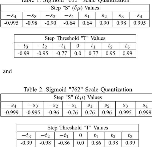
The step thresholds,T, that we chose are the means between
the step heights. The step-function mapping of passigns the
quantized value si, choosing isuch that ti 1 p ti. The
[image:4.612.321.556.55.220.2]two tested quantization scales are:
Table 1. Sigmoid "635" Scale Quantization
Step "S" ( ) Values
s4 s3 s2 s1 s1 s2 s3 s4
-0.995 -0.98 -0.90 -0.64 0.64 0.90 0.98 0.995
Step Threshold "T" Values
t3 t2 t1 0 t1 t2 t3
-0.99 -0.95 -0.77 0.0 0.77 0.95 0.99
[image:4.612.54.301.233.472.2]and
Table 2. Sigmoid "762" Scale Quantization
Step "S" ( ) Values
s4 s3 s2 s1 s1 s2 s3 s4
-0.999 -0.995 -0.96 -0.76 0.76 0.96 0.995 0.999
Step Threshold "T" Values
t3 t2 t1 0 t1 t2 t3
-0.99 -0.98 -0.86 0.0 0.86 0.98 0.99
Notice how, for both scales, the precision is concentrated in the regions of greatest certainty; the step functions have nely spaced steps at the two extremes. These families of quantizations suggest an implementation strategy for varying the decoder precision; such a strategy could compete with other adaptive error correction technologies that have been developed (rate compatible codes, etc.). The two quantizations tested differ only in how thexvalues of the sigmoidS(x)are selected.
B. Decoder Performance
We found that one of our quantization scales was better for lower SNR conditions and the other was better for high SNR conditions. A decoder intended to work well for a wide range of conditions might be designed to adapt its quantization as the channel conditions change. As channel conditions change, the current noise level could be estimated from the sample variance; we haven't yet built the logic needed to do this, but we understand it to be a common practice in signal processing. The SPA simulation results are shown in gures 8 (BER) and 9 (FER). The graphs show comparable results from a
0 1 2 3 4 5 6 7
10-10 10-8 10-6 10-4 10-2 100
SNR
BER
Sigmoid "635" 10 iters Sigmoid "762" 10 iters Planjery Proprietary 100 iters
Fig. 8. BER for Sigmoid "635" and "762", compared with Planjery et al
0 1 2 3 4 5 6 7
10-10 10-8 10-6 10-4 10-2 100
SNR
F
ER
Sigmoid "635" 10 iters Sigmoid "762" 10 iters Planjery Proprietary 100 iters
Fig. 9. FER for Sigmoid "635" and "762", compared with Planjery et al
simulation by Planjery, using their proprietary three-bit de-coder upon our own length 1162-bit LDPC code. The small vertical bars on the graph data points show the upper end of a 95% con dence interval for each of our simulation result values. These con dence intervals can be reduced with longer simulations (more samples). The con dence intervals that we present are small enough to rmly assert the following claims: The "635" quantization outperforms the "762" quantization over the [1.0,3.5] SNR range.
The "762" quantization outperforms the "635" quantization over the [4.0,5.0] SNR range.
At the10 4BER level, using our chosen rate-1
[image:4.612.319.558.263.431.2]C. Synthesis Results
In our quantization approach, as described above, limited precision is applied to the receiver sampling and to the variable node updates. Using this, we implemented a combined parity check and variable node update calculation using a mixture of calculations, logic, and a table lookup. The three-bit (6,3) parity check results in one of 112 possible output values, far less than the 2(3 5) input combinations. Another way to express this is as an implied quantization - the parity check output can be digitally represented using seven bits, since 112 < 27. The table lookup determines an update by specifying112 112 8 = 100352three-bit values. There are
additional symmetries which make it unnecessary to store this many computed table values. Our technique for nding the simpli cations was to allow the Altera Quartus II synthesis tool to do the simplifying for us. For our tested quantizations, the tool consistently digested the table lookup (speci ed in Verilog HDL) and produced a result with a complexity reduced by a factor of about 1000. The cost for each was an overnight, (81
2) hour, synthesis, place, and routing run.
The synthesis returns the number of logic elements (LE), which are required for the design and it computes, after placing and routing in an optimal manner, the longest path delay (LPD) between any pair among the inputs and outputs. The inverse of the LPD is the highest appropriate clock frequency for a clock-synchronous design.
The logic for calculating one variable update using two associated parity checks, synthesized to less than 5,000 logic elements. When the expressed design was expanded to include all three associated parity checks and compute all three of the resulting variable node updates, the design footprint more than doubled, but it did not triple. The delay increased by less than 20%. The three-message logic synthesized to a blend of shared computation and parallelism.
Table 3. Synthesis Results for each Quantization
msgs LEs LPD max clk
(ns) (MHz)
Planjery's algorithm 3 138 20.489 48.8
Sigmoid "635" Scale 1 4,743 36.255 27.5
3 11,111 43.099 23.2
Sigmoid "762" Scale 1 4,471 37.518 26.6
3 10,070 42.485 23.5
The chosen Cyclone II FPGA is too small to handle the 1162 replications of this design needed to process all of the bits of a code word simultaneously. A table lookup implementation is a good candidate for pipelining so a fast full-codeword design is entirely feasible.
Our synthesized design has twice the per-iteration latency of Planjery's published design (per our synthesis results). This computed factor of only two may be an overoptimistic comparison because some of both delays may be due to the overhead of directing input to and receiving output from the FPGA chip itself. To obtain a fairer comparison using these single iteration synthesis gures, we would omit some
input/output portion of the latency from the per iteration measure. We determined an upper bound for this contribution by implementing a very minimalist circuit, just an XOR of all of the inputs that also drives all of our outputs. That circuit, with three-bit inputs consumed 39 logic elements and had a latency of 17.560 ns. If we subtract off this latency time value from both longest path gures, then the Planjery/Vasic adds 2.929 ns to this minimal latency (to get the 20.489 ns total) and the "0.762" Sigmoid adds 24.925 to this minimal latency. The ratio of these two time durations is approximately eight to one. Since our decoder exceeds, in 10 iterations, the decoding gain of Planjery's proprietary decoder with 100 iterations, we compute the total decoding time for one bit to be
10 24:925 = 249:3ns for our design and100 2:929 = 292:9
ns for Planjery's published design. The timing advantage of our Sigmoid decoder is 15%.
The logic circuity of our decoder, with its quantizations, was larger than the logic to implement their decoder, but our de-coding operation was faster and obtains better dede-coding results for the tested regions of SNR, BER and FER. Our computation for one code symbol ts within the selected FPGA; we could readily use this to decode a full codeword in a serial fashion. Alternatively, we could increase throughput by using a larger chip or by redesigning for an ASIC. Using a larger chip would give us greater throughput and parallelization opportunities; these can be explored more thoroughly under the engineering constraints of a speci c application.
D. Further Work
With longer simulations we may determine how far down these performance curves go; explore more thoroughly the possible error oors of our approach and determine which of the approaches pushes down the error oor more. We have an alternative to longer and expensive simulations via our ongoing work in the importance sampling techniques that can be used to approximate simulations of very low error rate conditions. We previously studied the effect of varying the number of decoding iterations with this particular permutation-based LDPC code; we found that a decoding by 10 iterations was usually conclusive [8]. Simulations of our new quantized design in this paper with 100 iterations (instead of just 10) resulted in only minor additional gains (1
4 dB in terms of BER and 1
3 dB gain per the FER curves).
It bears mentioning that our simulation has the exibility to use different quantizations at each iteration. We have ex-perimented with this capability but we are without conclusive results.
V. COMPARINGDECODERS
The delity available at the receiver sampling point should not be discarded. The quantization selected for three-bits of precision does make a difference and considering the channel conditions is important when trying to choose the best possible quantization. Because we found that one of our quantizations was better in the lower SNR range and the other was better in the higher SNR range, we proposed a decoder that adapts between our two quantizations according to a frequent estimation of the channel conditions The 33,216 LE capacity of our FPGA could accommodate the logic of both of our quantizations, leaving enough additional room for the logic to measure the channel SNR and select the quantization adaptively. The adaptive decoder can beat Planjery's decoder by approximately 0.9 dB over a substantial BER range (10 2
to10 7).
Although the single iteration latency is greater than that of the Planjery et al design, our success with 10 iterations means that a decoder solution that is better for a range of SNR conditions can be reached in less time. We believe there is a potential for parallelization and pipelining, but even working through the bits one at a time in a serial fashion, the 430 ns per bit processing would support a decoding throughput over 2 Mbps. This FPGA-based capability is adequate to ful ll the diverse narrowband requirements and achieve the lower threshold for wideband operation of a contemporary radio system[20].
Our synthesis assessment is of Planjery's published design. We make two assumptions in order to compare our decoder to their proprietary design: (1) that the proprietary enhancements increase latency beyond that of the published design and (2) that the proprietary design requires additional logic. The comparison favors our decoder on two of three evaluation criteria. The comparison is summarized in the following table.
Table 4. Implementation Comparison
Our Planjery's designs
design pub. prop.
Decode 1 Bit (ns) 249.3 292.9 –
Gain @ 10 4 BER (dB) +8.5 +6.5 +7.6
Chip Area (LEs) 21,181 138 –
REFERENCES
[1] T. Zhang, K.K. Parhi, “A 54 Mbps (3,6)-regular FPGA LDPC decoder.” IEEE Workshop on Signal Processing Systems 2002 (SIPS '02), pages 127-132, Oct 2002
[2] S.K. Planjery, S.K. Chilappagari, B. Vasic, D. Declercq, L. Danjean, “Iterative Decoding Beyond Belief Propagation.” Information Theory and Applications Workship (ITA), pages 1–10, 2010
[3] Z. Zhang, L. Dolecek, B. Nikolic, V. Anantharam, M. Wainwright, “Design of LDPC decoders for improved low error rate performance: quantization and algorithm choices.” Communications, IEEE Transac-tions on Volume: 57 , Issue: 11, pages 3258–3268, 2009
[4] M.E. O'Sullivan, R. Smarandache, “High-rate, short length, (3,3s)-regular LDPC of girth 6 and 8.” Information Theory, Proceedings, IEEE International Symposium on, page 59, 2003
[5] M. Greferath, M.E. O'Sullivan, R. Smarandache, “Construction of good LDPC codes using dilation matrices.” Information Theory, Proceedings, International Symposium on, page 235, 2004
[6] Y. Chen, K.K. Parhi, “Overlapped Message Passing for Quasi-Cyclic Low-Density Parity Check Codes.” IEEE Transactions on Circuits and Systems, v. 51 no. 6, 2004
[7] M.M. Mansour, N.R. Shanbhag, “Low-power VLSI decoder architec-tures for LDPC codes.” Proceedings of the 2002 international sympo-sium on Low power electronics and design (ISLPED), pages 284–289, August 2002
[8] R. Moberly, M. O'Sullivan, “Representing probabilities with limited precision for iterative soft-decision LDPC decoding.” 2006 Wireless Personal Multimedia Conference, September 2006
[9] R. Moberly, M. O'Sullivan, “Computational performance of various formulations of the iterative soft-decision decoder algorithm.” 2000 IEEE International Symposium on Information Theory, pages 1703– 1707, July 2006
[10] J.Pearl.Probabilistic Reasoning in Intelligent Systems - Networks of Plausible Inference. Morgan Kaufmann, 1988
[11] B. Levine, R.R. Taylor, H. Schmit, “Implementation of near Shannon limit error-correcting codes using recon gurable hardware.” 2000 IEEE Symposium on Field-Programmable Custom Computing Machines, pages 217-226, April 2000
[12] D. Davey, M.C. MacKay, “Low-density parity check codes over GF(q).” IEEE Communications Letters, 2:165–167, June 1998
[13] A. Jimenez, K.Sh. Zigangirov, “Periodic time-varying convolutional codes with low-density parity-check matrices.” Proceedings 1998 IEEE International Symposium on Information Theory, page 305, Aug 1998 [14] M. Gokhale and P. Graham.Recon gurable Computing : Accelerating
Computation with Field-Programmable Gate Arrays, Chapters 1-4, Springer, Dordrecht, 2005
[15] M. Flynn, S.F. Oberman,Advanced Computer Arithmetic Design, Chap-ter 2, John Wiley and Sons Inc., New York, 2001
[16] B. Parhami,Computer Arithmetic - Algorithms and Hardware Designs, Chapters 1, 3, and 18, Oxford University Press, New York, 2000 [17] I. Koren,Computer Arithmetic Algorithms, Chapter 6, A.K. Peters Ltd.,
Natick, 2002
[18] M. Ercegovac, T. Lang,Digital Arithmetic, Chapter 8, Morgan Kauf-mann, San Francisco, 2004
[19] J.H. Han, M.H. Sunwoo, “Simpli ed sum-product algorithm using piecewise linear function approximation for low complexity LDPC de-coding.” ICUIMC '09: Proceedings of the 3rd International Conference on Ubiquitous Information Management and Communication, pages 302–309, February 2009