Pushover Analysis of RCC Set Back Building using
SAP2000
Bhatt Vandit
MTech-Structure, Department of Civil engineering Noble college, India
Abstract: The research revealed that three major factors, such as reserved strength, ductility and structural redundance Behaviour of multi-storey framed buildings throughout strong earthquake motion depend on the stiffness, strength and mass distribution in horizontal as well as vertical planes of the buildings. Damage occurring due to earthquake ground motion mainly starts at locations where structural weakness is present in the frames of multi-storey buildings. This weakness further increases and concentrates on the damage of structures by plastification resulting in the complete collapse of the building. In many cases, weakness occurs due to discontinuities in stiffness, mass or strength between two successive storeys. The storey discontinuities are often due to immediate variations in the geometry of frames along with the height. In past earthquakes, there are many examples of building failure due to such type of discontinuity in a vertical direction. Irregularity in configuration either in elevation or plan was sometimes recognized as one of the main causes of building failure during earthquakes. A common type of vertical irregularity (geometrical) in building develops due to a sudden reduction in the lateral dimension at specific levels of the building. This type of building is known as setback building. Many investigations have been performed to understand the behavior of setback buildings and to visualize methods for further improvement in performance.
Keywords: Static Nonlinear Pushover Analysis, Regular and Irregular Structure, Elevation Irregularity.
I. INTRODUCTION
Experiences during past seismic events have demonstrated that typical traditional methods of building design and construction lack in developing resistance to lateral forces in general and earthquake forces in particular. That’s why the concept of earthquake-resistant design came forward to enhance the behavior of structure during lateral loads. The basic approach of earthquake-resistant design should be to increase the lateral strength, deformability and ductility capacity of structure with limited damage but no collapse (Agarwal et al., 2010). This can be achieved by designing and detailing structure to get adequate toughness and ductility. This will lead to withstand the earthquake of any size and type, which is likely to experience during its lifetime. (Applied Technology Council, 1995; Osteraas et al., 1990)
Moreover, the response of symmetrical structures during earthquake events is far better than asymmetric structures (I.S. 13920-1993, 1993). It has well recognized that asymmetric buildings are especially vulnerable to earthquakes due to coupled lateral and torsional motions. The effect of such coupling and how well these effects are represented in seismic codes has been the subject of numerous investigations (Sunagar, 2012). The effects of coupling between lateral and torsional motions in the code designed systems were generally evaluated by comparing element ductility demands in asymmetric plan and the corresponding symmetric plan buildings. These investigations generally concluded that elements on the stiff side of the code designed asymmetric plan buildings are likely to suffer more damage, whereas elements on the flexible side are expected to suffer less damage (Wood, 1991).
In the present study, efforts have been made in estimating the seismic behavior of reinforced concrete medium-rise special moment-resisting frame (SRMF) having irregularity (asymmetry) in elevation by using non-linear static pushover analysis and compare it with codal values (Andrew et al., 1999; Balendra, 2003). The frame has been designed as per the guidelines of IS 456:2000. The lateral loads acting on the frames were obtained from the guidelines of IS 1893(part1). The non-linear pushover analysis is performed to find performance point and analyzed the behavior of the irregular structure.
II. MATERIALS AND METHODS
A. Computational Model
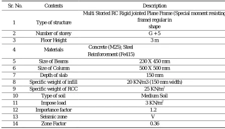
Table 1. Description of the modelled building used for the study
Sr. No. Contents Description
1 Type of structure
Multi Storied RC Rigid jointed Plane Frame (Special moment resisting frame) regular in
shape
2 Number of storey G + 5
3 Floor Height 3 m
4 Materials Concrete (M25); Steel
Reinforcement (Fe415)
5 Size of Beams 230 X 450 mm
6 Size of Column 500 X 500 mm
7 Depth of slab 150 mm
8 Specific weight of infill 20 KN/m3 (150 mm width)
9 Specific weight of RCC 25 KN/m3
10 Type of soil Medium Soil
11 Impose load 3 KN/m2
12 Importance factor 1.2
13 Seismic zone V
14 Zone Factor 0.36
The study considers two types of frame models; Irregular buildings and regular building. To validate the software generated results of regular building frame, those are compared with that of regular building as given in IS 1893(Part 1). As per IS 1893 (Part 1). A structure is defined to be irregular if the ratio of one of the quantities (such as mass, stiffness or strength) between adjacent stories exceeds a minimum prescribed value. However, in the recent version of IS 1893 (Part 1) irregular configuration of buildings has been defined explicitly. Five types of vertical irregularity have been listed. They are: vertical geometric irregularity, re- entrant corner irregularity, stiffness irregularity (soft storey), in-plane discontinuity in lateral-force-resisting vertical elements, and discontinuity in capacity. In this study we focus on vertical irregularities.
A regular building is the one which possess four attributes like: simple and regular configuration, adequate lateral strength, stiffness and ductility. Buildings having simple regular geometry and uniformly distributed mass and stiffness in plan as well as in elevation, suffer much less damage than buildings with irregular configurations (FEMA, 1995; FEMA, 2004). The model frames on which the studies made may include: regular reinforced cement concrete building, vertically irregular building.
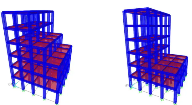
Modelling a building involves the modelling and assemblage of its various load-carrying elements. The model ideally represents the mass distribution, strength, stiffness and deformability. The beam-column joints are modelled by giving end-offsets to the frame elements, to obtain the bending moments and forces at the beam and column faces. The beam-column joints are assumed to be rigid (Lai et al., 1980; Lin et al., 2003).
Figure 2:3-d view of models having irregularity (IR1) Figure 3:3-d view of models having irregularity (IR2)
B. Pushover Analysis
The concept of a pushover analysis can be utilized for estimating the dynamic needs imposed on a structure by earthquake ground motions and the probable locations of the failure zones in a building can be ascertained by observing the type of hinge formations. The strength capacity of the weak zones in the post-elastic range can then be increased by retrofitting.
Nonlinear static pushover analyses of the three study frames are performed. For this analysis nonlinear plastic hinges have been assigned to all of the primary elements. First-moment hinges (M3-hinges) have been assigned to beam elements and then axial-moment 2- axial-moment3 hinges (PMM-hinges) have been assigned to column elements.
In the study, the height from the base to Centre of gravity of container is 18m and hence the target displacement is set to 72 mm. The displacement is applied step-by-step to the structure in an incremental manner. The base shear and roof displacement are recorded at every step. Due to the plan symmetry of the structure, the pushover analysis is carried out in X direction only. Hence, earthquake loads of tank full conditions are given in X-direction only.
C. Performance-Based Analysis
The modern approach of performance-based engineering offers a rational design framework for making design decisions by assessing the appropriate risks and meeting various performance objectives of the engineered facilities that are subjected to natural hazards. Performance-based seismic design and assessment guidelines for new buildings and other structures have been proposed by several FEMA programs (FEMA-350;
FEMA-P695; FEMA-P752). With the scale and complexity of modern tall buildings, the seismic performance-based design requires extensive computational resources and effort. Performance-based design optimization is a combination of state-of-the-art.
The performance-based analysis is a simplified, static- nonlinear analysis under a predefined pattern of permanent vertical loads and gradually increasing lateral loads. Typically, the first pushover load case is used to apply gravity load and then subsequent lateral pushover load cases are specified to start from the final conditions of the gravity pushover. Typically, a gravity load pushover is force-controlled and lateral pushovers are displacement controlled. The load is applied incrementally to frameworks until a collapse mechanism is reached. Thus, it enables the determination of collapse load and ductility.
D. Analytical Calculation of Design Base Shear
Vb = Ah W [1]
W = Seismic weight of building Z = Zone factor
I = Importance factor
R= Response Reduction Factor
Figure4. Pushover curve of R1 Frame
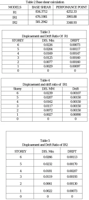
Table 2 Base shear calculation
MODELS BASE SHEAR PERFOMANCE POINT
R1 834.3712 4252.33
IR1 676.1981 3993.88
IR2 581.2942 3348.93
Table 3
Displcaement and Drift Ratio Of R1
STOREY DIS. Mm DRIFT
6 0.0226 0.00073
5 0.0204 0.00117
4 0.0169 0.00147
3 0.0125 0.00160
2 0.0077 0.00160
1 0.0029 0.00097
0 0 0
Table 4
Displcaement and drift ratio of IR1
Storey DIS. MM Drift
6 0.0239 0.00107
5 0.0207 0.00150
4 0.0162 0.00150
3 0.0117 0.00150
2 0.0072 0.00150
1 0.0027 0.00090
0 0 0
Table 5
Displcaement and Drift Ratio of IR2
STOREY DIS. Mm DRIFT
6 0.0266 0.00113
5 0.0232 0.00170
4 0.0181 0.00207
3 0.0119 0.00193
2 0.0061 0.00130
1 0.0022 0.00073
III. CONCLUSION
Based on the results obtained from the pushover analysis carried out in SAP2000, there developed a pushover curve that gave rise to the evaluation and calculation of many values. Using the significance of these values which include maximum base shear and maximum drift capacity.
In this study, the seismic performance of RC frames irregular in elevation was investigated. For this purpose, several types of vertically irregular frames were first modeled in sap2000 software and then nonlinear static analysis was performed was demonstrated that the life safety performance criteria are almost satisfied in the regular frames.
It was shown that the seismic performance of the studied multi storey reinforced concrete frame buildings with setbacks along height cannot be considered satisfactory.
It could be said that, although the design procedure provided by Code seems to be successful for regular frames, it cannot be able to satisfy the life safety performance level criteria in irregular frames with setback along with their height.
REFERENCES
[1] Agarwal P and Shrikhande M (2010). Earthquake Resistant Design of Structures. PHI learning private limited, New Delhi. [2] Andrew W, Gary H, Christopher R (1999). Seismic response modification factors. Journal of Structural Engineering, 125: 438-444.
[3] Balendra T and Huang X (2003). Over strength and Ductility Factors for Steel Frames Designed According to BS 5950. Journal of Structural Engineering, 129: 1019-1035.
[4] BIS I.S. 13920-1993 (1993). Ductile detailing of reinforced concrete structures subjected to seismic forces- code of practice, New Delhi. [5] BIS I.S. 1893-2002 (2002). Criteria for earthquake resistance design of structures- Part1, New Delhi.
[6] BIS I.S. 456-2000 (2000). Plain and reinforced concrete – code practice, New Delhi.
[7] Federal Emergency Management Agency (1995). NEHRP Recommended Provisions for Seismic Regulations for New Buildings, Washington, DC. [8] Lai SP and Biggs JM (1980). Inelastic Response Spectra for Aseismic Building Design. Journal of Structural Engineering. 106: 1295-1310.
[9] MagarPatil HR and Jangid RS (2015a). Numerical study of seismic performance of steel moment resisting frame with buckling restrained brace and viscous fluid damper. IES Journal Part A: Civil and Structural Engineering, 8: 165-174.
[10] MagarPatil H R and Jangid RS (2015b). Development and analysis of passive energy dissipation system for steel moment resisting frame. International Journal of Civil and Structural Engineering, 5: 339-352.
DECLARATIONS Author’s contribution