Abstract—End milling is a very common metal cutting process used for the machining of most types of metal. The process is inherently intermittent causing the tool tip edge to constantly fluctuate between various levels of temperatures, specifically from cold to 300oC when cutting Al alloy. During dry end milling cutting temperatures need to remain within the design specifications of the tool tip. Even working with Al alloy the tool tip is subjected to thermal cyclic stresses. Conventional wisdom states that it is essential to use flood cooling during end milling, as intermittent cooling increases the effect of thermal shock and build up edge. Al alloy - unlike other materials - needs cutting fluid to avoid smearing the insert edges and to improve the surface finish.
Modern machining companies constantly face the challenges of environmental issues that affect the manufacturing costs of machined parts. New environmental manufacturing techniques need to be developed for companies to remain competitive in the future. The research presented in this paper represents the experimentation involved in determining a suitable environmental alternative to using copious amounts of cutting fluid during end milling of Al alloy. Previous experimental evaluation of Minimal Quantities of Lubrication (MQL) when applied to the machining of Al alloy has proved to be inconclusive.
Index Terms—End milling, environmental issues, flood coolant, thermal shock, Minimal Quantities of Lubrication.
I. INTRODUCTION
HE machining process involves removing unwanted material from the workpiece in the form of chips, and is one of the principal methods of manufacturing. According to Childs [1] the wealth of nations can be judged by their investment in machining. Modern manufacturing trends require parts to be produced quickly, and with as small a carbon footprint as possible. This is directing machining processes towards higher cutting speeds, lower waste and improved part quality, making it necessary to use coolant. Having adequate cooling and lubrication during
Manuscript received February 10, 2012; revised March 20, 2012.
Feasibility Study of Adopting Minimal Quantities of Lubrication for End Milling Aluminium
Brian Boswell is a Lecturer at Curtin University Perth Western Australia 6845, corresponding author phone: +61 8 9266 3803; fax: +61 8 9266 2681; (e-mail: b.boswell@ curtin.edu.au)
Mohammad Nazrul Islam is a senior Lecturer at Curtin University Perth Western Australia (e-mail: m.n.islam@curtin.edu.au).
metal cutting is essential to reduce thermal shock and stresses generated during machining. These factors have a substantial impact on the tool life, quality, and the power consumed. The customary end milling process uses copious amounts of liquid coolant [2], with the liquid coolant being used to increase the tool life and to improve the workpiece surface finish. Unfortunately, even with the recognition of the aforementioned benefits, a more environmentally suitable tool cooling method is sought, as ecological and health costs can be contributed to the cutting fluid. Liquid coolant supports the growth of micro-organisms [3] such as aerobic bacteria, anaerobic bacteria and fungi which are the most notable microbial group [4]. Obviously the health and safety aspects of using cutting fluids add to the cost of metal cutting as suitable disposal of the cutting fluid is needed [5]. A number of alternative cooling methods have been trialed to help reduce the amount of liquid coolant used, while having no adverse effect on the machining performance [6]. One such method is called Minimal Quantities of Lubrication (MQL) [7]. This is where an extremely small amount of lubricant is blasted by air into the cutting zone. Previous research has shown that MQL has been effective in prolonging tool life when machining steel workpieces [8, 9]. A research paper by Rahman [10] examined the design of a new cooling system which used liquid mist and air in end milling. Additional research for machining steel conducted by Rahman [11] has shown MQL to be compatible to that of flood coolant for cutting conditions within the following range: cutting speed 75 to 125 m/min, feed rate 0.01 to 0.03 mm/tooth, and a depth of cut of 0.35 to 0.7 mm. Fig. 1 shows the flank wear and surface roughness recorded for a feed rate of 0.015 mm/tooth, and depth of cut of 0.35 mm..
Fig.1. Effect of cutting speed on tool wear and surface roughness by Rahman [10]
When contrasted with the production cutting conditions it was found that the flank wear had increased as expected,
Feasibility Study of Adopting Minimal
Quantities of Lubrication for End Milling
Aluminium
Brian Boswell, Mohammad Nazrul Islam
and that MQL was not as effective due to the higher cutting temperatures. As yet there has not been the same rigorous research into the machining of Al alloy. One paper has investigated the effect of using MQL on tool wear, chip morphology and surface finish produced during machining A356 Al alloy at high cutting speed. It was found that the use of MQL to replace flood coolant in high speed machining of Al alloy had been demonstrated to be successful [12]. However, there were some technical issues still to be resolved such as tool wear and machine reliability. The machining parameters selected for this research were typically those which are suitable for most CNC milling machines. A hypo-euthectic grade of Al-Si alloy (6061) was selected as it has medium to high strength properties, and has a machinability rating of 1.9 [2]. The machinability of Al alloys primarily depends on the Si content of Al-Si alloy (Si content between 0.4 and 0.8%). Unlike most other milling applications, cutting fluid should always be used when machining Al to avoid smears and to improve the surface finish. The dominant wear criteria when machining Al alloy is built-up-edge, burr formation and poor surface finish. Burr formation or surface finish is best to use as tool life criteria as it is difficult to observe wear on the tool tip when machining Al alloy.
This research endeavor’s to show the effectiveness and suitability of MQL to prolong tool life during the end milling of Al alloy. The Taguchi method [13] was used to strategize the experimental procedure and optimized the experimental machining parameters used in the tests.
II.CUTTING TESTS AND SET-UP
The metal cutting tests consisted of a Leadwell vertical machining center (V-30), a Kistler three component dynamometer (Type 9257BA) and a Yokogawa CW140 clamp on power analyser. An Airtx vortex tube (Model 20008) with an inlet pressure of 85 psi supplied chilled air at a temperature of -5oC. The compressed air used was
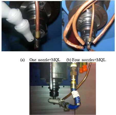
[image:2.595.305.547.357.457.2]supplied from the workshop airline. The MQL was delivered from a Uni-max cutting tool lubrication system which distributed atomised coolube metalwork lubricant to the cutting zone. This system operates on the same principle as a Serv-O-Spray allowing the lubricant to be sprayed from a single air source, which allows adjustment to the amount of lubricant delivered to the cutting zone. The proper selection of cutting fluid is often neglected in machining practice as many cutting fluids which are suitable for use with ferrous materials are not suitable for machining Al alloys. A traditional emulsified cutting fluid (Cocol ultra cut) was used for the wet test machining as this is suitable for Al. The cutting tool selected for all of the tests was a Sandvik single tip tool (R390-012A16-11L) with a coated tungsten carbide insert (R390-11 T3 08E-NL H13A). All cooling nozzles used during the tests were kept at approximately 25 mm from the tool during all tests. The combined cold air and MQL nozzle was able to be placed closer to the cutting zone. A single tooth cutter was selected to avoid the influence of tool run out on the flank wear, and to simplify the analysis of the tests. The workpiece was clamped onto the dynamometer that in turn was secured onto the machine table of the vertical milling center. Cutting forces were then recorded onto the computer’s hard disk for later analysis. Fig. 2 shows the cutting test set-up.
Fig. 2 Force measuring set-up
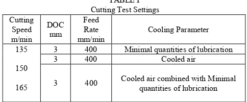
Cutting tests were carried out using five conditions; dry, flood, cooled air, MQL and combine cooled air with MQL. Typical machining practices were used to machine the face ensuring that the tool tip was constantly removing 70% of the material along the tool path. The cutting forces and power were measured for each face machined. The cutting conditions used were selected to reflect typical working conditions as shown in TABLE I.
TABLE I Cutting Test Settings Cutting
Speed m/min
DOC mm
Feed Rate mm/min
Cooling Parameter
135
150
165
3 400 Minimal quantities of lubrication
3 400 Cooled air
3 400 Cooled air combined with Minimal quantities of lubrication
Dry and flood workpieces were also end milled to provide the appropriate comparison of these two extreme conditions. In this research the tool failure criteria applied to the cutting edges were:
1. Part surface quality and burr formation.
2. Flank wear VB greater than 0.3 or maximum notch
wear of 1.0 mm.
3. Dramatic change in tool forces and cutting power. All tool tips were examined for wear after the machining of each test sample by using a tool maker microscope, and the surface roughness of the workpieces was measured by a Mitutoyo portable stylus type surface roughness tester.
III.RESULTS AND DISCUSSIONS
Although Al alloys are some of the most machinable of the common materials used there are still some machining issues to be aware of. The low melting point of the material and having one of the highest coefficients of expansion along with relative softness and elasticity makes it necessary to dissipate the generated heat. Otherwise, it is difficult to maintain tolerances of the workpiece. Al alloys normally have significant amounts of Si causing them to be adhesive, promoting rapid heat generation resulting in chip welding and built-up-edge. Rapid machining of Al alloy allows the development of a hard Al oxide film on new exposed
Dynamometer End mill
Coolant nozzle
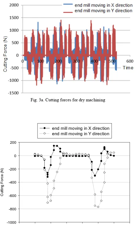
surfaces. This oxide film produces galling and smearing rather than good chip formation causing rapid degeneration of the cutting edge. All tested workpieces generate large amounts of data; a typical output from the dynamometer for dry machining is shown in Fig. 3a. The dynamometer was used to measure the forces acting on the tool tip for each new machined face of the workpiece. Examining this output helps identify areas of interest during the cutting process. A more detailed analysis of two revolutions of the cutter is possible as shown in Fig. 3b which examines X direction forces (the milling machine table moving left or right), and the Y direction forces (the milling machine table moving to the back, or moving to the front) as shown in Fig. 2. The cutting force shown in Fig. 3c combines the X and Y forces at the same 400 second point.
Fig. 3a. Cutting forces for dry machining
Time (s)
400.025 400.030 400.035 400.040 400.045 400.050 400.055 400.060
C
u
tt
in
g F
or
c
e
(N
)
-1000 -800 -600 -400 -200 0 200
[image:3.595.49.287.272.669.2]end mill moving in X direction end mill moving in Y direction
Fig. 3b. Dry X and Y forces at 150 m/s
Time (s)
400.025 400.030 400.035 400.040 400.045 400.050 400.055 400.060
C
u
tti
n
g
F
o
rc
e
(N)
0 200 400 600 800 1000
Fig. 3c. Dry cutting force at 150 m/s
The output from the dynamometer allows changes in the cutting conditions to be observed, with a more detailed cutting analysis possible when the sample time is reduced. However, this would restrict the analysis of the cooling process used during machining of the workpiece face. A detailed analysis of the cutting engagement of the tool tip can clearly be seen over two revolutions of the tool Fig 3b; both the X and Y directional forces are given. Examination of the two cutting cycles for MQL cooling Fig. 4, and dry cutting Fig. 3c shows a large reduction in cutting forces for MQL.
Time (s)
400.165 400.170 400.175 400.180 400.185 400.190 400.195 400.200
C
u
tt
in
g For
c
e (
N
)
[image:3.595.56.289.274.444.2]0 100 200 300 400 500 600
Fig .4. Maximum cutting force during MQL at 150 m/s
[image:3.595.307.540.417.575.2]Dry Air MQL MQL + Air Flood 0
200 400 600 800 1000 1200 1400
[image:4.595.307.548.62.203.2]Force Power
Fig. 5a. Cutting forces and Power
[image:4.595.60.269.66.230.2]As expected when the cutting speed increased the cutting force reduced, which was observed for all the cooling methods. Fig. 5b shows this for MQL and MQL and air.
Fig. 5b. Cutting force over a range of cutting velocities
The second method used to determine the effectiveness of the cooling process is by examining the surface finish Fig. 6. as anomalies on the surface are quite apparent.
Fig. 6. Surface damage indicating tool tip deterioration
The surface finish data Fig. 7 showed that MQL produced comparable surface finish as flood end milling even at higher cutting speed. However, the workpiece retained much of the generated heat.
Dry Air MQL MQL + Air Flood
Ra
(
m
m︶
[image:4.595.35.243.308.484.2]0.0 0.2 0.4 0.6 0.8 1.0 1.2 1.4
Fig. 7. Surface roughness at 150 m/min
The challenge for MQL when machining Al alloy is to dissipate the heat from the workpiece to insure dimensional integrity. Combining air cooling with MQL looked like the obvious answer to keep the workpiece cool while achieving good surface finish workpieces. The cold air cooling test for Al alloy did not achieve the same improvements at the tool tip as was obtained when machining steel, as the temperature at the tool tip was too low to induce thermal cracking reducing tool life. Previous research conducted by Kelly [14] and Diakodimitris [15] determined that the alignment of the nozzle in relation to the tool can optimise the tool life when MQL is machining Al alloy. To facilitate this; new cooling nozzles were designed incorporating cold air and MQL Fig. 8. A number of designs were tested with the most efficient design being used in this research. To reduce the workpiece temperature the tool tip was constantly surrounded with cold air with the addition of a small quantity of vegetable oil Fig. 8c. The mist levels produced by the nozzle are important for two reasons. First, the effectiveness of the machining operations is dependent on both the concentration of mist that reaches the cutting zone, and the oil droplet size of the mist. The design of the nozzle also needs to assist in reducing airborne emissions of the oil mist as it is directed at the cutting zone [16]. This is important for occupation, health and safety purposes.
(a) One nozzle+MQL (b) Four nozzles+MQL
(c) Combined cold air and MQL nozzle
Fig. 8. Development of cooling nozzle
MQL MQL + Air
Fo
rc
e (
N
)
0 100 200 300 400 500 600 700
Col 1 vs 135 m/s - 135 m/s Col 1 vs 150 m/s - 150 m/s Col 1 vs 165 m/s - 165 m/s
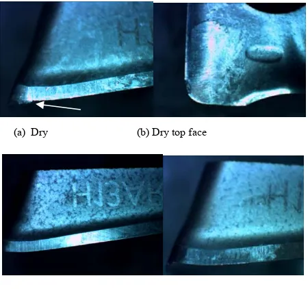
[image:4.595.312.538.539.762.2] [image:4.595.79.236.565.666.2]Generally the most inclusive cooling method is shown by the most reduction in tool wear. However, machining Al alloy wear is difficult to determine, even with the use of a microscope, as depicted in by the tool tip pictures in Fig. 9, where only the dry tool tip shows the start of a built up edge at the arrow.
(a) Dry (b) Dry top face
[image:5.595.57.282.149.360.2](c) Wet (d) MQL
Fig. 9. Tool tip wear
IV.CONCLUSIONS
The demand for environmental sustainable manufacturing is the primary drive for technology that reduces the use of liquid coolant. However, determining the effectiveness of the cooling parameters cannot be judged simply by considering one function only. Metal cutting is a very complex system, and a small change in cutting conditions can have major consequences. To determine the best cooling method it was necessary to consider a number of factors.
Did the cooling method increase tool life? Was the surface finish appropriate? Had the workpiece met the tolerance?
Was the method more sustainable than traditional wet coolant?
It was shown in Fig. 5 that MQL had the lowest cutting force followed by MQL + cooled air, indicating an efficient machining performance. In addition MQL and MQL + cooled air achieved surface finishes as compatible to that of flood coolant. These results confirm that MQL + air cooling met two of the criteria needed to be considered as equivalent as or better than traditional flood cooling. These goals were all achieved by combining air cooling + MQL in a suitable redesigned nozzle. Although air cooling with the use of a small amount of vegetable oil is not a totally dry process it is quite close and therefore is sustainable.
The results have shown that cold air + MQL can be used for end milling with normal production cutting speeds, feed rates and depths of cut. It must be observed that the operational use of the nozzle may be considered
cumbersome and for this reason machine operators may not like employing this cooling system in practice. Further work is necessary to examine how the nozzle can be made to be user friendly for the machine operator.
REFERENCES
[1] T. H. C. Childs, K. Maekawa, T. Obikawa, and Y. Â Â. Â Yamane, "Metal Machining - Theory and Applications," ed: Elsevier, 2000. [2] T. J. Drozda, Ed., Machining (Tool and Manufacturing Engineers
Handbook. Dearborn Michigan: Mc Graw-Hill Book Co, 1976, p.^pp. Pages.
[3] M. Soković and K. Mijanović, "Ecological aspects of the cutting fluids and its influence on quantifiable parameters of the cutting processes,"
Journal of Materials Processing Technology, vol. 109, pp. 181-189, 2001.
[4] C. O. T. a. E. O. Bennett, "The Growth of Aerobic Bacteria in Metal-Cutting Fluids," Applied Microbiology, vol. 6, p. 4,
1958.
[5] G. M. Calvert, E. Ward, T. M. Schnorr, and L. J. Fine, "Cancer risks among workers exposed to metalworking fluids: A systematic review,"
American Journal of Industrial Medicine, vol. 33, pp. 282-292, 1998. [6] Y.-K. Hwang, C.-M. Lee, and S.-H. Park, "Evaluation of machinability
according to the changes in machine tools and cooling lubrication environments and optimization of cutting conditions using Taguchi method," International Journal of Precision Engineering and Manufacturing, vol. 10, pp. 65-73, 2009.
[7] K. Weinert, I. Inasaki, J. W. Sutherland, and T. Wakabayashi, "Dry Machining and Minimum Quantity Lubrication," CIRP Annals - Manufacturing Technology, vol. 53, pp. 511-537, 2004.
[8] B. Boswell, "An experimental approach to determining the effectiveness of minimum liquid cooling for end milling 1040 steel," presented at the 6th Australasian Congress on Applied Mechanics, ACAM 6, Perth, 2010.
[9] N. Boubekri, "A technology enabler for green machining: minimum quantity lubrication (MQL)," Journal of Manufacturing Technology Management, vol. 21, p. 556, 2010.
[10] M. Rahman, A. Senthil Kumar, and M. U. Salam, "Experimental evaluation on the effect of minimal quantities of lubricant in milling,"
International Journal of Machine Tools and Manufacture, vol. 42, pp. 539-547, 2002.
[11] M. Rahman, A. Senthil Kumar, U. I. S. Manzoor, and U. I. S. Manzoor, "Evaluation of Minimal of Lubricant in End Milling," The International Journal of Advanced Manufacturing Technology, vol. 18,
pp. 235-241, 2001.
[12] H. A. Kishawy, M. Dumitrescu, E. G. Ng, and M. A. Elbestawi, "Effect of coolant strategy on tool performance, chip morphology and surface quality during high-speed machining of A356 aluminum alloy,"
International Journal of Machine Tools and Manufacture, vol. 45, pp.
219-227, 2005.
[13] R. Roy, A Primer on the Taguchi Method: Society of Manufacturing
Engineers, 1990.
[14] J. F. Kelly and M. G. Cotterell, "Minimal lubrication machining of aluminium alloys," Journal of Materials Processing Technology, vol. 120, pp. 327-334, 2002.
[15] P. H. a. Y. R. I. C. Diakodimitris. (2010, 12 Dec. 2011). Study of Minimum Quality Cooling (MQC) on the tool temperature in milling
operations. Available:
http://msep.engr.wisc.edu/phocadownload/cirp44_study%20of%20min imum%20quantity%20cooling.pdf