Towards the Spatial Database Specification for
GIS using Z-Notations
Farooq Ahmad, Salahuddin Khan and Sher Afzal Khan
Abstract—Formal methods are mathematical techniques use in design, development and verification of software and hard-ware system. Geographic information systems GIS use to collect, store, analyze and present spatial informations. GIS databases are usually very complex to design. Formal methods can play an important role in their design. In the paper, the authors investigate an approach of formal specification of spatial databases for GIS systems usingZ notation (a formal language with a powerful structuring mechanism). For the purpose, we use an example from the context of GIS and spatial database to draw Entity Relationship Diagram ERD. Further the paper presents transformation from Entity Relationship DiagramERDto formal specification that shows all the entities and their relationships in Z notation. In this paper we exhibit that the approach is applicable for spatial database designing. Consequently this leads to unambiguous, consistent and verified GISsystem.
Index Terms—Formal Methods, Z-Notations, GIS, Spatial databases, Conceptual design.
I. INTRODUCTION
G
EOGRAPHIC Information SystemsGISare extremely complex software, hence specification methods are very important for their quality especially for: consistency of data models, different component interfaces, and in database architecture [3]. Existing methods offer large amounts of text and diagrams, which often creates ambiguity and problems to scale up large problems where the greater amount of documentation require. Due to these problems, it is argued to develop software model for designingGIS. For this there are many useful models of GIS, which are designed by using informal approaches in ad-hoc fashion. Consequently, it is difficult for GIS designer to fully capture Modularity and to remove ambiguous, inconsistency and to verify step by step to a system. In order to remove such errors we propose formal approach based upon transformation of ERD diagram to Z- notation. This would help GIS designer to verify his system early at the design level.According to Woodcock et al. [11] Z is model-oriented approach, and has a powerful structuring mechanism. It can be used to specify information systems in combination with natural language. The formal methodZis based on discrete mathematics such as predicate logic, set theory, functions and relations. It is used for specifying the behavior of abstract data type and sequential programs. The Z-specification di-vides the specification of complex system in different states
Manuscript received June 05, 2012; revised July 12, 2012. The travel grant for this work is supported by the Higher Education Commission of Pakistan for oral presentation.
Farooq Ahmad is with the Faculty of Information Technology, University of Central Punjab, lahore, Pakistan e-mail:[email protected].
Salahuddin Khan is with the Department of Computer Sciences, SZABIST- Islamababd, Pakistan e-mail:[email protected].
Sher Afzal Khan is with the Department of Computer Sciences, Abdul Wali Khan University, Mardan, Pakistan e-mail:[email protected].
called schemas. The schema consists of three parts; the first one is the schema name which is in the top line, the second part between the first and second line is the schema signature which is the set of names and types of entities introduced in a schema. The third part under the middle line is called the schema predicate which is used for the set of properties and shows the relationships between the entities and the variables defined in the schema signature. These schemas can be combined to produce the overall description of the system. The paper address schemas in the specification part of the paper. The Z-specification cannot typically be executed by computers, but the standard tools are available which are used for checking syntax and proof of the formal specification, leads to quality of specification and this allows mistakes to be detected and corrected sooner in the design life cycle. Formalization is the process of the design of representations of infinite phenomena by a finite set of distinct symbols, [4]. The use of formalization process basically facilitates to understand the underlying structure and theory in the model [1].
The organization of the paper is as follows: Section 2 describes Geographic Information Systems GIS, spatial databases and their conceptual model. Section 3 describes related work that has been done regarding use of formal methods inGISand spatial databases. In section 4, Formal specifications of conceptual design of spatial databases are demonstrated using Z-notations. In Section 5, we present the proof and verification of syntax used in our proposed approach. In the end, we give conclusion and references.
II. GEOGRAPHICINFORMATIONSYSTEMSGIS
In the past, efforts have been made to defineGISfrom a variety of angles. This diversity of perceptions has lead to innumerable definitions forGIS, based on the type of user and application domain. In view of current capabilities of GIS, it can be defined as ”an information system used to store, organize, retrieve, analyze, output and update spatially referenced data, in order to support decision making for planning and management of activities like natural resources and environmental management, transportation and telecom-munication utilities, commerce and business affairs, defense services, and various administrative management”, Debashis Chakraborty and Rabi N. Sahoo (2007).
The major functional units of typical geographic informa-tion systems GIS consist of Data Input Unit, Data Model, Data Manipulation Capabilities, and Result Presentation Fa-cilities [6].
But now with the evolution of GIS, spatial data is better maintained, easy to search, analyze and represent, and can be shared safely along-with simple updating mechanisms, Debashis Chakraborty and Rabi N. Sahoo (2007). Due to this, a significant amount of time and money is saved, efficiency is improved and most importantly, now we can expect a better decision-making ability.
A few examples of use of GIS technology are that by mapping the locations of school-age children can help to know where school is needed, mapping crime incidents helps to know need for increased police patrol, mapping customer’s home and work locations can help bank placeATMmachines to provide better service, mapping properties of city can help users to locate a specific address or property owner andGIS systems also helps businessmen or marketers to find new prospects.
There are many popular commercial GIS software but GIS products by Environmental Systems Research Institute ESRIhave made it a world leader inGISindustry. Its GIS solutions like ArcInfo, ArcView, and ArcGIS have become a de facto standard for those who want to model spatial systems using maps, topological and remote sensing data [7].
III. RELATEDWORK
According to Andrew et al. [3] formalization of geographic space in Geographic Information SystemsGISis considered. Formalization is the representation of model of the world by means of formal language. It is also proposed that relational databases can be considered as representations of formal models. Tables are representations of the extension of a particular relation. In order to perform query processing, algebraic operations on the rows and columns in the table are performed. It is also proposed that by viewing GIS as implementations of formal theories of the geometry of geographic space, we can consider the spatial databases as representations of formal models of formal theories of geographic space and GISoperations as model based proof procedures.
Belussi et al.[5] proposed a Layered Spatial Data Model LSDM for the representation of geographical information in different layers and maps. The data model is based on the concept of feature type which are roads, lakes, etc. The main feature of the proposed data model is the ability to represent maps in which the geometry of its objects is not completely known. A language for querying layered maps is also presented. The proposed model and language have been implemented on top of a commercial object-relational spatial database system.
Jianchun et al. [10] proposed a formal specification data model FSM using the formal specification languages and techniques, which is a representation for describing the semantics of objects and their relationships. The purpose of giving this FSM is to generate common framework schema integration in multidatabase systems and solve the schematic conflicts among local schemas. The FSM provides types and properties to model the real-world objects. Alejandro et al. [2] formally defined dimension predicate and a method for discovering all the valid dimension predicates between two spatial objects of any type and complexity is presented. The concept of dimension predicates turns out to be useful not
only in high-level applications but also as part of a develop-ment hierarchy that includes robust geometric primitivesRGP which represent building blocks of the well known complex spatial data types like point, line and region. Applying di-mension predicates toRGPsduring development may benefit correctness of the implemented data type model. Huiqing et al. [9] explored a method based on an apartment web service application, which uses geospatial data to improve accuracy and quality of online information. The great strength of the spatial data is to query about the location and direction of spatial objects. A simple fuzzy model for direction query is introduced. Querying examples in the paper have shown the capabilities of a spatial database to support fuzzy directional queries.
IV. FORMAL SPECIFICATION FOR CONCEPTUAL MODEL OF SPATIAL DATABASE
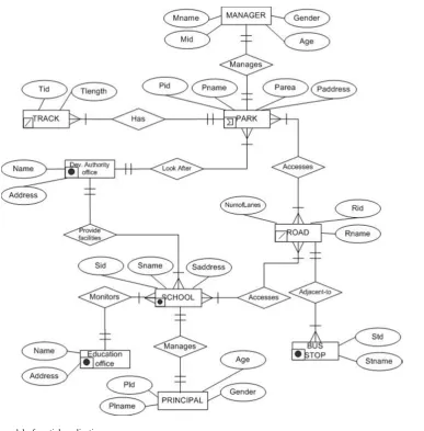
In order to show use of formal specification in spa-tial databases of GIS, we will use an example of spatial application domain. This application will map the parks, schools, road accessing the schools and parks, and bus-stops adjacent to these roads. This application will help the City Development Authority to recognize the need of more green space, schools, roads accessing the parks and schools, and bus-stops at suitable places. There are managers for parks and schools who look after and manage the activities there. Parks and Schools are accessed by roads and each road has bus-stops adjacent to it. City Development Authority provides different facilities to parks and schools. Education Authority office monitors the standard and activities of schools.
A. Business Rules
Business Rules are statements that describe and confine aspects of the business and state business structure. The business rules for our spatial application domain are as follows;
• Each PARK has a MANAGER, and a MANAGER can manage only one PARK. No two PARKs have same MANAGER.
• EachPARKhas one or more TRACKsfor walk. • EachPARKis accessed by one or manyROADs, and a
ROADcan access one or morePARKs.
• DEV. AUTHORITY provides facilities to all PARKs and each PARK get facilities fromDEV. AUTHORITY. • Each SCHOOL is managed by a PRINCIPAL, and a
PRINCIPALcan manage only oneSCHOOL.
• EachSCHOOLis accessed by one or manyROADs, and aROADcan access one or manySCHOOLs.
• DEV. AUTHORITY provides facilities to all SCHOOLs and each SCHOOL get facilities from DEV. AUTHORITY.
• EDUCATION AUTHORITY monitors the activities of all SCHOOLs, and each SCHOOL is accountable to EDUCATION AUTHORITY.
B. Entity Relationship Diagram of Example
Next, on the basis of above mentioned business rules, we will draw Conceptual model or Entity Relationships diagram ERD with pictograms for our spatial application. The conceptual model of our spatial database is shown in the entity relationship diagram in Figure 1.
C. Formal Specification for entities of Entity Relationship Diagram (ERD)
Now, we will use formal methods to define the Formal schemas for entities of above mentioned Entity Relationship Diagram in Z-Notation by using Z/EVES tool. Schema is a two-dimensional notation in which declarations for the objects appear in the upper part and constraints on the objects appear in the lower part. In Z, when a variable is introduced for the first time in a specification documents its type must be given which is just a collection of objects. The basic type is enclosed in square brackets when it is being introduced. So in all the schemas below, first line which is in bracket, introduces basic types. Then objects of those types and functions are declared in upper portion of schema and constraints in lower portion as described above.
[Parkid, Parkname, Parkarea, Parkaddress]
Park
Pid:PParkid
Pname:PParkname
Parea:PParkarea Paddress:PParkaddress
Parkattribrel:ParkidParkname×Parkname
×Parkarea×Parkaddress
Pid=domParkattribrel
[Trackid, Tracklength, Lineid]
Track
Tid:PTrackid
Tlength:PTracklength Lid:PLineid
Trackattribrel:TrackidTracklength×Lineid
Tid=domTrackattribrel
[Roadid, Roadname, RNumoflanes]
Road
Rid:PRoadid Rname:PRoadname Numoflanes:PRNumoflanes Lineid:PLineid
Roadattribrel:RoadidRoadname
×RNumoflanes×Lineid
Rid=domRoadattribrel
[Schoolid, Schoolname, Schooladdress, Pointid]
School
Sid:PSchoolid Sname:PSchoolname Saddress:PSchooladdress Pointid:PPointid
Schoolattribrel:SchoolidSchoolname
×Schooladdress×Pointid
Sid=domSchoolattribrel
[Principalid, Principalname, Gender, Age]
Princiapl
Plid:PPrincipalid Plname:PPrincipalname
Plgender:PGender
Page:PAge
Principalattribrel:PrincipalidPrincipalname
×Gender×Age
Plid=domPrincipalattribrel
[Managerid, Managername]
Manager
Mid:PManagerid
Mname:PManagername
Mgender:PGender
Mage:PAge
Managerattribrel:ManageridManagername
×Gender×Age
Mid=domManagerattribrel
[Standid, Standname]
BusStand
Standid:PStandid
Standname:PStandname
Pointid:PPointid
Busstopattribrel:StandidStandname×Pointid
Standid=domBusstopattribrel
[DevAuthorityName, DevAuthorityAddress]
DevelopmentAuthority
Authorityname:PDevAuthorityName
Authorityaddress:PDevAuthorityAddress
Pointid:PPointid
Devattribrel:DevAuthorityName
(DevAuthorityAddress×Pointid)
Authorityname=domDevattribrel
[EduofficeName, EduofficeAddress]
EducationDepttoffice
Eduoffname:PEduofficeName
Eduoffaddress:PEduofficeAddress
Pointid:PPointid
Eduattribrel:EduofficeName
(EduofficeAddress×Pointid)
Fig. 1. Conceptual model of spatial application
D. Formal Specification for relations between entities of Entity Relationship Diagram (ERD)
Now, we will define the Formal schemas for relationships between entities of above mentioned Entity Relationship Diagram in Z-Notation by usingZ/EVEStool.
[Parks, Managers, Tracks, Roads, DevAuthority, Schools, Principals, EduOffice, BusStops]
ParkManagement Cityparks:PParks
Citypmanagers:PManagers
Manage:ParksManagers
Cityparks=domManage Citypmanagers=ranManage
ParkDescription ΞParkManagement Cityptracks:PTracks
Contained:Parks↔Tracks
Cityparks=domContained Cityptracks=ranContained
AccessPark ΞParkManagement Cityroads:PRoads
Paccess:Parks↔Roads
Cityparks=domPaccess Cityroads=ranPaccess
ParkFacilitation ΞParkManagement
CityAuthority:PDevAuthority
Providefacilities:Parks 7→DevAuthority
Cityparks=domProvidefacilities CityAuthority=ranProvidefacilities
SchoolManagement Cityschools:PSchools Citysprincipals:PPrincipals Manage:SchoolsPrincipals
SchoolMonitoring ΞSchoolManagement CityEduoffice:PEduOffice Monitors:Schools 7→EduOffice
Cityschools=domMonitors CityEduoffice=ranMonitors
AccessSchool SchoolManagement Cityroads:PRoads Saccess:Schools↔Roads
Schoolfacilities ΞSchoolManagement
CityAuthority:PDevAuthority
Getfacilities:Schools↔DevAuthority
Cityschools=domGetfacilities CityAuthority=ranGetfacilities
RoadBusStops ΞAccessSchool
Citybusstops:PBusStops
Adjacentto:Roads↔BusStops
Cityroads=domAdjacentto Citybusstops=ranAdjacentto
It is clear from above mentioned formal specification that it is unambiguous and understandable by only one way. The use of this formal specification will be helpful in a great deal for designer of complex spatial databases to perform further design processes.
V. VERIFICATION OFSPECIFICATION
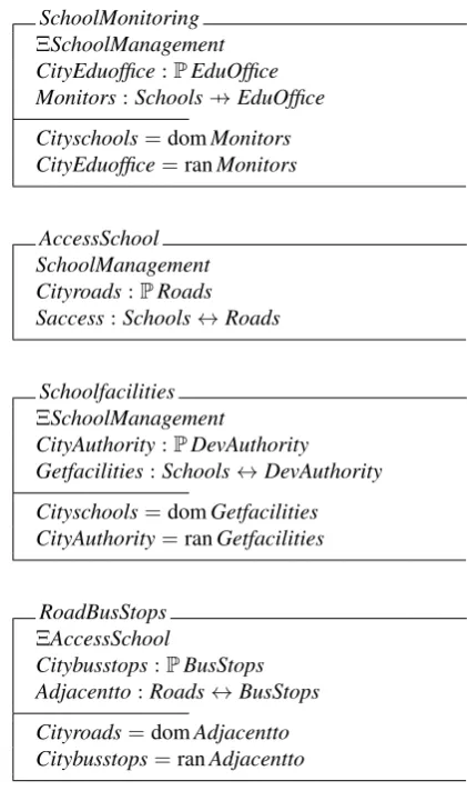
The formal schemas mentioned in previous section are implemented and verified by Z/EVES tool. Some of the snapshots of verification of these schemas are shown in following fligure 2(a) shows schemas for description of enti-ties and figure 2(b) shows schemas for relationship between entities. The main screen consists of three columns. First columns shows the verification of syntax, Second column shows verification of proof, and Third column contains the specification.
VI. CONCLUSIONS
In this paper, a brief introduction of Formal methods and Geographic Information Systems GIS is given along with the application of formal methods in spatial databases development. It is showed that conceptual models of spatial databases can be formalized in formal systems. The database concept is vital component of all GIS systems and differ-entiates it from other simple computer supported mapping systems, which may produce good quality maps but can neither highlight the important relationships between features nor provide any form of analysis. By using formal methods, a model is considered as an algebraic structure which consists of sets of individuals, relations, and functions. Relations and
(a)
[image:5.595.61.272.54.415.2](b)
Fig. 2. Z/EVES verification of Z- specification
functions of the model correspond to relations, properties, and processes in the world. These models use some formal language to represent conceptual models. In this paper, I have used Z -notation that has powerful structuring mechanism and is based upon set theory and mathematical logic. The main reason of using Formal methods in Conceptual design was that they provide a compact description of the entities and relationships between them.
REFERENCES
[1] Adrijana Car and Andrew U. Frank 1995: Formalization of Conceptual Models for GIS using GOFER. In Proceedings of GIS/LIS ’95 Central Europe, in Budapest, Hungary, pp: 8
[2] Alejandro Pauly, Mark McKenney, Reasey Praing, and Markus Schnei-der 2005: Dimension Refined Topological Predicates. In Proceedings of the 13th annual ACM international workshop on Geographic informa-tion systems
[3] Andrew U. Frank and Werner Kuhn1995: Specifying Open GIS with Functional Languages. In 4th International Symposium on Large Spatial Databases, SSD’95, in Portland, USA, 184-195
[5] A. Belussi, B. Catania, and E. Bertino November 2003: A Reference Framework for Integrating Multiple Representations of Geographical Maps. Proceedings of the 11th ACM international symposium on Advances in geographic information systems GIS ’03
[6] Brajesh Goyal, Shashi Shekhar, Mark Coyle, Duen-Ren Liu, and Shyamsundar Sarkar 1997: Data Models in Geographic Information Systems. Communication ACM 40(4): 103-111
[7] David G. Jenkins and Lisa A. MacCauley 2006: GIS, SINKS, FILL, and Disappearing Wetlands: Unintended Consequences in Algorithm Development and Use, Symposium on Applied Computing 2006: Pro-ceedings of the 2006 ACM symposium on Applied computing, Pages 277-282
[8] Debashis Chakraborty and Rabi N. Sahoo 2007: Fundamentals of Geographic Information System, Viva Books Private Limited [9] Huiqing H. Yang, Geoffrey L. Tranard 2006: An Online Information
System for Apartment Services with Fuzzy Spatial Queries. IKE’06: Proceedings
[10] Jianchun Zhang 1994: A Formal Specification Model and Its Applica-tion in Multidatabase Systems. In Proceedings of the 1994 conference of the Centre for Advanced Studies on Collaborative research [11] Jim Woodcock and Jim Davies 1996: Using Z Specification