Power Quality Improvement by using Shunt Active
Power Filter
Zehara Zeenat1, Dr. Nishant Patnaik2
1, 2
EEE Department, ANITS
Abstract: This paper presents the performance analysis of shunt active power filter using UVT(Unit V ector Template) method. This shows how to reduce or eliminate the various power quality issues for a three-phase balanced and unbalanced composite load i.e. (linear load and non-linear load) by using shunt active power filter. The governing method used to reduce the various power quality issues is UVT method for both three-phase balanced and unbalanced composite load. The various power quality issues are – harmonic compensation, reactive power compensation and improvement of power factor. Simulation results are tabulated for both three-phase balanced and unbalanced composite load.
Keywords: Balanced and Unbalanced Load, Reactive Power Compensation, Shunt Active Power Filter, THD, UVT
I. INTRODUCTION
Due to the extensive usage of power electronic based equipment for both domestic and industrial purpose there is a rise in power quality issue. The power quality issue is a major concern across the world. But the power electronic based equipment that is used for domestic and industrial purpose consists of both linear and non-linear loads. This power electronic based equipment mainly consists of non-linear loads that lead to power quality issues. Especially, due to increase in demand of non-linear load there is a decrease power quality. Some of the power quality issues are harmonics, reactive power demand, power factor, signaling voltages, voltage fluctuations, voltage dips and interruptions, voltage balance, power frequency variations etc. Examples of non-linear loads are computers, fax machines, printers, PLCs, refrigerators, televisions. One of the major power quality issues is harmonics. And apart from harmonics reactive power compensation is also the major quality issue that leads to disturbances in power systems. For these power quality issue we use filters. Based on the efficiency, the most widely used filter is active power filter. This filter does not compensate harmonics but also the reactive power compensation is also met. Due to which the source rms current is constant. Different configurations of active power filters have been developed. In this paper, shunt active power filter is used. The governing method used for both three-phase balanced and unbalanced composite load is UVT method i.e. (Unit Vector Template method). Here the power quality issues are analysed.
pulses for the three-phase voltage source converter a pulse generator is used. The pulse generator consists of a hysteresis controller. The control algorithm discussed here is Unit Vector Template method.
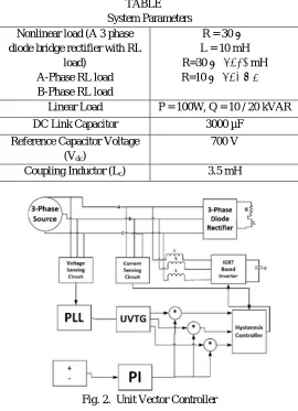
TABLE System Parameters Nonlinear load (A 3 phase
diode bridge rectifier with RL load)
A-Phase RL load B-Phase RL load
R = 30 Ω,
L = 10 mH
R=30 Ω, L=10 mH
R=10 Ω, L=5 mH
Linear Load P = 100W, Q = 10 / 20 kVAR
DC Link Capacitor 3000 µF
Reference Capacitor Voltage (Vdc)
700 V
Coupling Inductor (Lc) 3.5 mH
Fig. 2. Unit Vector Controller
III. UNIT VECTOR CONTROLLER
1) Balanced Load: A schematic block diagram of a three-phase balanced load is shown in the above figure (b). A three-phase source is connected to a three-phase composite load. The composite load consists of a non-linear load and a linear load. Non-linear load introduces harmonics and Non-linear load causes reactive power demand. A three-phase voltage sensing circuit is connected to the PLL (Phase Locked Loop). By using PLL three unit’s sine vectors are generated displaced by 120 degrees at
each other. The output of PI controller and unit sine vector are multiplied to generate reference source currents i.e. Isa*,Isb*,Isc*.
Here active filter used is a two-level three phase IGBT based voltage source converter connected to the mains at PCC (Point of Common Connection) through a coupling inductor. The function of coupling inductor is to reduce the ripple current of compensating current being injected at PCC. For generating the switching pulses for the converter a hysteresis controller is used
[image:2.612.171.441.222.595.2](a)
(b)
(c)
(d)
(e)
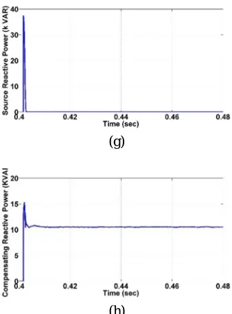
(g)
[image:4.612.221.390.78.306.2](h)
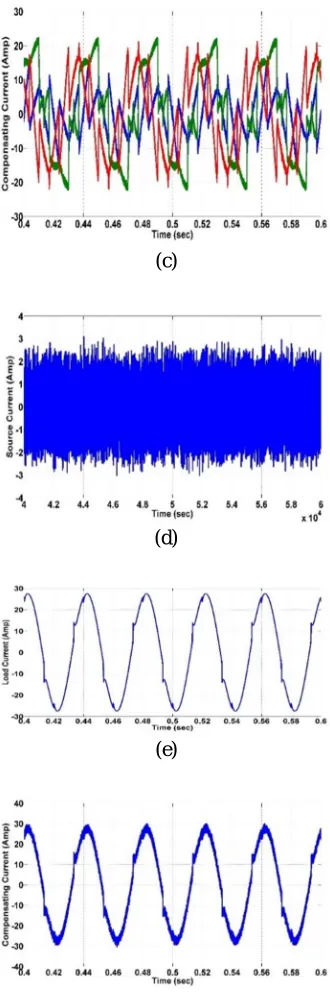
Fig. 3. Simulation Results Of Apf Using Unit Vector Template Method For Balanced Three-Phase Load (A). Source Voltage (Vph).
(B). Dc Link Capacitor Voltage (Vdc). (C). Load Current (Il) (D). Source Current (Is) (E). Compensating Current (Ic) (F). Load
Reactive Power (Ql). (G). Source Reactive Power (Qs). (H). Compensating Reactive Power (Qc)
2) Unbalanced Load: Two Single-Phase Non-Linear Load Are Connected To Phase A And Phase B. The Uvt Controller For Unbalanced System Is Similar To Balanced Case With Some Modifications. For Unbalanced Case Three Phase Four Leg Inverter Is Used Where Fourth Leg Is Connected To The Neutral Line Between Source And Load. The Fourth Leg Can Be Controlled For Neutral Current Compensation. The Reference Neutral Current Is Generated By Summation Of Three Reference Source Current. It Is Compared With Actual Neutral Current In Hysteresis Controller To Generate The Switching Pulse For The Fourth Leg Of The Inverter.
(a)
(c)
(d)
(e)
(f)
Fig. 4. Simulation Results Of Apf By Using Unit Vector Template Method For A Three-Phase Unbalanced Load (A). Source Current Is (B).Load Current (Il) (C). Compensating Current.(Ic) (D). Source To Neutral Current (Isn) (E). Load To Neutral
Current(Iln). (F). Compensating Neutral Current(Ic).
TABLE THD Of Source Current
Load type
Without
APF With APF
Nll (Balanced) 33.07% 4.1%
[image:5.612.223.388.81.577.2]shows the load neutral current is compensated by compensating neutral current in fig. 4. (f). Fig. 4. (d) shows source neutral current is zero.
V. CONCLUSION
An Active Power Filter Based On Unit Vector Template Controlling Technique Is Presented in this paper. Two important power quality parameters are analyzed in detail, namely, current harmonic and reactive power compensation which in turn affects the input side power factor. THD for only non-linear load reduces from 33.07% to 4.1%. THD for only non-linear and linear load reduces from 23% to 3.5%. Reactive load demand at 10kw is been compensated by the filter. Thus, it is clear that along with harmonic suppression, reactive power compensation can be performed in a controlled manner.
REFERENCES
[1] H. Akagi, “New Trends in Active Filters for Power Conditioning,” IEEE Transactions on Industrial Electronics, vol. 32, no. 6, 1996.
[2] B. Singh, K. Al-Haddad, and A. Chandra, "A review of active filters for power quality improvement," IEEE Transactions on Industrial Electronics, vol. 46, pp. 960-971, 1999.
[3] Vasco Soares, Pedro Verdelho, and Gil D. Marques, "An Instantaneous Active and Reactive Current Component Method for Active Filters," Power Electronics, IEEE Transactions on, vol. 15, no. 4, 2000.
[4] Shailendra kumar jain and Pramod Agarwal, “Design Simulation and Experimental Investigations, on a Shunt Active Power Filter for Harmonics, and Reactive Power Compensation,” Electric Power Components and System, 31:671–692, 2003.
[5] M. El-Habrour, M.K. Darwish, and P. Mehta, "Active power filters: a review," Electric Power Applications, IEE Proceedings, vol. 147, pp. 403-413, 2000. [6] Nishant Patnaik and Anup Kumar Panda, “Comparative Analysis on a Shunt Active Power Filter with different Control Strategies for Composite Loads”. IEEE
2014
[7] Bhim Singh, Kamal Al-Haddad, Senior Member, IEEE, and Ambrish Chandra, Member, IEEE. “A Review of Active Filters for Power Quality Improvement”1999
[8] Shailendra Kumar Jain, Pramod Agarwal and H.O Gupta - “Design Simulation and Experimental Investigations on a Shunt Active Power Filter for Harmonics and Reactive Power Compensation”-2002.
[9] Suresh Mikkili and AK Panda, “Real-time implementation of PI and fuzzy logic controllers based shunt active filter control strategies for power quality improvement,” International Journal of Electrical Power & Energy Systems, vol 43, pp 1114-1126, 2012.