interface for navigating immersive robotic systems
Mohammad Abu-Alqumsan1, Felix Ebert2 and Angelika
Peer3
1 Chair of Automatic Control Engineering, Technical University of Munich
(TUM), Munich, Germany
2 Institute of Autonomous Systems Technology, University of the Bundeswehr,
Munich, Germany
3 Bristol Robotics Laboratory, University of the West of England, Bristol, UK
E-mail: [email protected]
Abstract. Objective. This work proposes principled strategies for self-adaptations in EEG-based Brain-computer interfaces (BCIs) as a way out of the bandwidth bottleneck resulting from the considerable mismatch between the low-bandwidth interface and the bandwidth-hungry application, and a way to enable fluent and intuitive interaction in embodiment systems. The main focus is laid upon inferring the hidden target goals of users while navigating in a remote environment as a basis for possible adaptations. Approach. To reason about possible user goals, a general user-agnostic Bayesian update rule is devised to be recursively applied upon the arrival of evidences, i.e. user input and user gaze. Experiments were conducted with healthy subjects within robotic embodiment settings to evaluate the proposed method. These experiments varied along three factors: the type of the robot/environment (simulated and physical), the type of the interface (keyboard or BCI), and the way goal recognition (GR) is used to guide a simple shared control (SC) driving scheme. Main results. Our results show that the proposed GR algorithm is able to track and infer the hidden user goals with relatively high precision and recall. Further, the realized SC driving scheme benefits from the output of the GR system and is able to reduce the user effort needed to accomplish the assigned tasks. Despite the fact that the BCI requires higher effort compared to the keyboard conditions, most subjects were able to complete the assigned tasks, and the proposed GR system is additionally shown able to handle the uncertainty in user input during SSVEP-based interaction. The SC application of the belief vector indicates that the benefits of the GR module are more pronounced for BCIs, compared to the keyboard interface.
Significance. Being based on intuitive heuristics that model the behavior of the general population during the execution of navigation tasks, the proposed GR method can be used without prior tuning for the individual users. The proposed methods can be easily integrated in devising more advanced SC schemes and/or strategies for automatic BCI self-adaptations.
Keywords: Adaptive BCI, SSVEP, Intention Recognition, Shared Control, Robotic Embodiment
1. Introduction
Brain-computer interfaces (BCIs) aredirect communi-cation and control channels between the brain and arti-ficial devices like computers, prosthetic limbs or robots. Thedirectness here refers to the fact that BCIs bypass the natural neural (outside the brain) and muscular pathways [1] which are required for all other kinds of human-human and human-machine interaction. Typi-cally in BCIs, the users’ brain signals are decoded into machine actions using a mapping that is known to both the users and the devices they control or communicate with.
Recently, there has been growing interest in deploying BCIs in immersive robotic embodiment systems [2–7], whereby the objective is to allow users to exercise physical and social interaction in a remote environment through robotic avatars, which are typically equipped with locomotion and manipulation capabilities in order to allow for enhanced interaction. Hereby and throughout this work, the termsimmersion
and embodiment are used similarly to Slater and
Sanchez-Vives [8]. That is,immersion is used to refer to the objective description of the system technicalities that enable the users’ perception of the remote environment based on their natural sensorimotor contingencies (e.g. head tracking). On the other hand,
robotic embodiment is used to define the process of
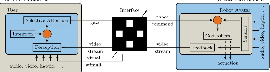
replacing the user’s body by a robotic avatar, where one speaks of the senses of self-location, agency and body ownership as subcomponents of embodiment [9]. Fig. 1 depicts a schematic of a closed loop BCI-based immersive robotic embodiment system. Users continuously receive perceptual feedback from their robot avatar embedded in the remote environment and communicate their intentions by selectively attending to (or gazing at) one of the available interface elements. Other BCI paradigms like motor imagery (MI) are possible [5], but we are mostly concerned in this work with BCIs based on selective attention, e.g. P300 and SSVEP-based BCIs. Ultimately, in order to fully immerse users in the remote environment, the perceptual channels from the local environment should be replaced by the ones that reflect the state of the avatar in the remote environment. In this regard, vision is the most important perceptual modality, but other modalities undoubtedly would enhance the user subjective experience of immersion and embodiment. The robot, on the other side, continuously receives user
commands and translates them using available low and high level controllers into robotic actions, that change the state of the environment or of the robot itself.
Generally speaking, at each time instant during BCI-based interaction, only a limited number of interface elements can fit into the interface, whether that be based on P300, SSVEP or MI and consequently, only a few commands will be available to users. This gives rise to the primary challenge in robotic applications of BCIs, that is, the considerable mismatch between the low-bandwidth interface and the bandwidth-hungry application. Hierarchical menu style BCI and adaptive BCIs offer a way to allow for an extended set of robotic actions and thus to overcome the bandwidth mismatch.
User Robot Avatar Remote Environment Local Environment
Interface
Perception Selective Attention
Feedback
Intention Controllers
Sensors
gaze
robot command
video stream video
stream visual
stimuli actuation
audio,
video,
haptic,
..
.
[image:3.612.78.531.70.192.2]audio, video, haptic, . . .
Figure 1: Closed loop BCI-based robotic embodiment system. Users communicate their intentions by selectively attending to one of the interface elements, which are typically shown overlaid on the visual feedback arriving from the remote environment. Self-adaptations in the BCI allow for extended set of actions available to the users. An SSVEP-based interface is shown as an example here.
the user behavior, on the basis of general behavioral patterns that are observed in humans during task execution. The Bayesian framework is designed for the general population allowing to infer user intentions, without any prior training. The output of the Bayesian inference module is a belief vector that sorts all target goals in the environment according to how probable they are given the observed evidence. Moreover, a novel metric that measures the non-uniformness of the belief vector is proposed as to reflect upon the confidence of the inference system in its computed beliefs. To show the usefulness of the computed beliefs and confidence measures, a simple probabilistic shared control scheme is devised so that adaptations are applied to the robot movements, according to the belief/confidence information. In order to evaluate the performance of the designed Bayesian inference module, experiments were conducted with healthy subjects in an immersive robotic embodiment setup and in simulation. Results show that the intention recognition system is able to track the hidden user goals with relatively high accuracy. When the belief of the intention recognition module is used to modulate parameters of the robot movement, less user effort (measured by the number of interaction) is required to accomplish the assigned tasks.
This paper proceeds as follows. Sec. 2 provides background information about adaptive interfaces in the context of robotic navigation, to motivate the work on intention and goal recognition. Sec. 3 provides a short review on state-of-the-art approaches to intention recognition for robotic navigation tasks. Our Bayesian goal inference systems is introduced in Sec. 4. Detailed information about the experiments used to evaluate the proposed methods is described in Sec. 5. Experimental results are reported in Sec. 6 followed by a discussion in Sec. 7. This paper concludes in Sec. 8.
2. Background and Motivation
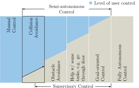
User commands in BCI-based robotic navigation applications range from commanding the mobile base to move for some distance in one direction, to commanding the mobile base to move to a specific location or to autonomously perform complex maneuvers like “move to the kitchen” or “walk through the doorway”. Obviously, the varying degrees in the goal-directness of incoming user commands require adequate levels of autonomy at the robot side. And conversely, by deciding first on the level of autonomy, adaptive interfaces can suggest conforming sets of commands for interaction. The exact relation between the interface and the level of autonomy, therefore, can be decided upon either by the interface itself as in [11] or by the user as in [12, 13]. Either way, the higher the robot autonomy, the less control is left to the user. In a general sense, robot autonomy is thought of here as a continuum where the fully autonomous and fully manual control modes are its extremes. Often the selection of the optimal point on the autonomy continuum is done in two steps. First, the continuum is discretized into different general levels (or modes) [14, 15] and the appropriate mode is selected. The optimal point of automation is then selected within that mode. In the context of robotic navigation applications, we borrow from [16] and adopt the 6 basic levels or robot operation modes shown in Fig. 2.
Ingoal-oriented control mode, users only
Level of user control Level of robot autonomy
Supervisory Control Semi-autonomous
Control
Man
ual
Con
trol
Collision
Av
oidance
Obstacle Av
oidance
Help
w/
some
tasks,
e.g.
go
through
do
or
Goal-orien
ted
Con
trol
F
ully
Autonomous
Con
[image:4.612.64.291.70.214.2]trol
Figure 2: Robot operational modes for navigation tasks. The level of automation can be modulated within each mode of operation as well.
obstacle avoidance mode, it is the robot’s job to exe-cute maneuvers that avoid obstacles while the human user is issuing commands that move it through the en-vironment. In thecollision avoidance mode, a typical behavior of the robot is to halt movement in the face of obstacles while the user is commanding movements. As hinted previously, the different automation levels define the nature of interface self-adaptations. For instance, in the goal-oriented mode, the interface might provide the user with the most probable next goals (or goal locations) in the environment. Such predictions can be performed on the basis of the transition probabilities between the different goals in the environment, which can be learned e.g. from the history of user interaction with the system. In absence of any knowledge about the user preferences in the domain, other interface adaptation strategies should be devised. One possible approach, is to allow users to interact with the robot in a lower autonomy mode, so that some evidence can be gathered throughout interaction and used to predict the target goals of the user.
In this work, we mainly focus on the problem of goal recognition during interaction within the collision avoidance mode, where user input is additionally restricted to incremental commands that translate or rotate the robot in the different directions with predefined steps. The reason for this is threefold. First, it has been noted in [17], that powered wheelchair users want to actively drive the wheelchair rather than being merely its passengers. The same can be said about the users of teleoperation/embodiment robots, and therefore, it is imperative to give users the sense of control they need [18], as much as can be allowed by other existing constraints like the safety of the human, the machine and the environment, the capabilities of the robot and the abilities/disabilities of the human
users. The collision avoidance mode leaves most of the control in the hands (or rather the brains) of the users, and at the same time guarantees navigation safety. Second, and most importantly, it allows us to develop the methodologies, by which gathered evidence from user commands in low autonomy levels can guide the interface self-adaptations in the higher autonomy modes. Third, with long term interaction with the robot, transition probabilities can be learned, and used later to guide interface adaptations in higher autonomy modes. The next section will provide a brief review on the problem of goal/intention recognition in general, with some emphasis on intention recognition in navigation tasks.
3. Related Work: Goal/Intention Recognition
The termplan recognitionhas been defined by Schmidt et al. [19] as the process of inferring an agent’s goals from observing the actions the agent is performing in the domain and organizing these actions into a plan structure which explicitly describes the goal-subgoal relations among them. Conformingly, recent research on human action understanding within navigation contexts shows that a machine equipped with inverse planning is able to efficiently model this cognitive process [20]. We refer interchangeably to the agent whose actions are observed as the actor or the user, whereas the observing agent that makes the inference is referred to as therecognizer.
The goals refer to desired states of the world or states of knowledge about the world. In order to arrive at these states, an actor needs to perform a sequence of actions that defines aplan. Actions taken might change the state of the world, or the state of the actor’s knowledge about the world. Actions are defined by their preconditions, i.e. possible states in which they can take place, and effects that describe the state transition when the action is performed. In some domains, it is possible to enumerate all possible goal states and plans an actor might have. The set of these plans is referred to as plan library.
The problems of plan and goal recognition have many details in common. Systems which try to infer the final target state only are referred to
as goal recognition (GR) systems, and those which
be referred to asintention recognition systems†. Intention recognition systems can be classified with respect to the actor’s attitude towards the recognizer into three categories. First, the keyhole recognition refers, as the term suggests, to the case when the actor is not aware of the existence of the recognizer [21, 22]. In the second category, which is referred to as intended recognition, the actor cooperatively chooses actions which reduce the ambiguity about his/her hidden intentions [23]. Finally, adversarial recognition concerns itself with the case when the actors actively try to confuse the recognizer by choosing misleading actions [22, 24].
Charniak and Goldman [25] argue that the problem of intention recognition is largely a problem of inference under conditions of uncertainty, rendering the probabilistic approaches of best fit. Such approaches introduce a numerical measure of belief that reflects how likely or probable individual plans are and can thus, explicitly represent the uncertainty associated [26]. The vector that contains the probability of all plans (or goals) is often referred to as the belief vector. Bayesian networks, and in particular, dynamic Bayesian networks (DBNs) are probably the mostly used probabilistic method for intention recognition in different domains, e.g. for predicting user plans in a game [21].
In robotic navigation contexts, Perrin et al. [27] use a DBN for goal recognition, in a system, with which the user interacts by either confirming or rejecting its propositions. The proposed Bayesian network addi-tionally includes variables that integrate the time of the day, whether the phone is ringing and the previ-ously visited goals. The conditional probability distri-butions (CPDs) used in the network are learned from training sequences. Alternatively, goal recognition is realized in [17] on the basis of simple metrics that are computed from the distances and relative orientations the wheelchair has to available goal locations (available doors in this case). On the other hand, several ap-proaches have regarded the goal/plan recognition prob-lem as a planning probprob-lem [28–30]. The main idea here is that, instead of enumerating all the plans in the do-main, which is not always feasible, a general planner can be used to generate the possible plans to all avail-able target states. Along these concepts, the works in [31, 32] use a recursive Bayesian update for plan recognition based on environmental data, global path planning, and history of interaction. The Bayesian up-date hereby is defined with
† Other abstraction levels exist. For instance, the user might want to move to the kitchen to prepare a meal, and this very objective of the user can be considered the user intention.
Pk(ik−m:k|uk−m:k) = (posterior)
P(uk|ik−m:k, uk−m:k−1) (user model) P(ik|ik−m:k−1, uk−m:k−1) (plan process model) Pk−1(ik−m:k−1|uk−m:k−1) (prior)
η, (normalization)
(1)
where ik is the user mental plan to move from the cur-rent location to the target location in mind,uk is the user input at time instantk,uk−m:k is the sequence of the user input from time instant k−m to k, and m defines the past time instances that influence the plan and the user input at any time. Hereby, for instance, the user model defines the likelihood of the user input given that the user has the plan evolution ik−m:k and issued previous commands uk−m:k−1. The user and plan process models are defined differently for a variety of systems and inputs. For a BCI-based input and free space area [31], the user model is defined with a simple heuristic function that takes into consideration the rel-ative orientations of the robot to the different goals and the distances to each of them. The plan process model is computed such that when the robot moves from the posexk−1 toxk, the straight path between xk−1 and the jth goal is transformed into the straight path be-tween xk and thejth goal, and thejth probability is transferred to the new path. More detailed user and plan process models are proposed in [32] for joysticks and deterministic discrete interfaces for different kinds of environments.
we aim at goal recognition systems that require no training whatsoever, so that users can benefit from the recognition system in their first use. On the other hand, straightforward methods like [17] may not be able to exploit useful available information, e.g. the previous user actions towards the target goal.
4. Methods: Bayesian Framework to Goal Recognition in Navigation Tasks
4.1. Problem Statement
The objective of the goal recognition module is to infer users’ target goals throughout interaction, where evidence is gathered from observed users’ commands and their directions of gaze. It is assumed here that the users are unaware of the existence of the recognizer, i.e. keyhole intention recognition.
We denote the set of enumerable goals in the environment with G = {1gW,2gW,
· · ·,n Wg
}, where each goal is defined by its pose with respect to the global coordinate system of the available map (W), such that m Wg = [m Wx , ym W, zm W, θm W]T, where
m ∈ {1,2,· · ·, n} and m Wθ
∈ [−π, π] is the smallest angle between the x-coordinate of themth goal frame and that of the global frame (W), where the z-coordinate of all goals is parallel to that of the world frame. We assume that the number (n) and the poses of these goals, which might represent the location of salient objects the user frequently uses, are accessible by the goal recognition system. For the sake of simplicity in the notation, the postscriptW is dropped when we refer to goals and their poses in the global coordinate system. The unknown target goal, which the user has in mind, is defined here as a discrete random variableGwith a sample spaceG.
While having a goal locationmg in mind at time instant k, the user updates the mental path plan
i
m
k of how to arrive there from the robot’s current pose xk = [xk, yk, θk]T. We write this in the form,
i
m
k =xk→mg. Additionally, we define the length of a path plan (in meters) with l(mi
k) = mlk. In order to follow the plan in mind, the user issues a command uk ∈ U. In this work, we only consider incremental commands that can be issued with discrete interfaces (e.g. keyboard or SSVEP-BCI), and therefore, the set of all possible commands is enumerable, i.e. U =
{move forward, move backward, move left, move right, turn left, turn right, stop}. User commands are translated into robot actionsak that change the state of the robot fromxk toxk+1. The change in the robot pose that is triggered by translational and rotational commands is set respectively to the default values δddef(m/command) andδθdef(rad/command).
In order to make the math easier to follow, we introduce the dummy user commandu0, which implies
x0 = x1 and mi0 = mi1 for all m. The user’s gaze direction at time instantkis denoted byhk, which we assume here to be defined with the rotational angles of the gaze direction relative to an arbitrary reference frame.
We assume that the localization module provides a reliable estimate of xk, and that the mental path plans to all goals (i.e. xk → mg) of the user can be estimated reliably with a global path planner on the basis of the 2D cost map of the environment, denoted by Mk. Implicitly, with this assumption we hypothesize that users in the navigation domain act approximately optimally (rationality assumption [20]) and try to follow the path that minimizes some cost function. The global path planner is expected to find paths similar to the ones the user plans for the different goals.
Therefore, we can assume that at time instantk, the GR module has access to the following information
• The observed sequence of user commands up to time instant k, which is denoted by u0:k = (u0,· · ·, uk).
• The observed sequence of user gaze up to timek, which is denoted byh0:k= (h0,· · ·,hk).
• The sequence of plans computed to all goals up to time instant k, denoted by 1:ni
0:k = (1i
0:k, . . .ni0:k), wheremi0:k = (x0→mg,· · ·,xk→
g
m ).
The problem of goal recognition can be then formally defined as estimating the probability
P
m
k =Pk(G=mg|u0:k,h0:k,1:ni0:k),∀m, (2) where Pn
m=1mPk = 1 for all k. The probabilities of all goals can be concatenated in the n-dimensional vector Pk which encodes the system belief about the user’s hidden goal at time instant k, where Pk = [1P
k, P2 k,· · ·, Pn k]T. In this work, Pk is referred to as thebelief vector.
We assume that before the user starts navigating in the remote environment, the GR module has no prior knowledge about the next pursued goal, and therefore mP0 = 1/n,∀m. Additionally, the subscript
kis reset to 0 each time the robot arrives at one of the available goals, which automatically resets the belief vector to a near-uniform distribution, wherein the last visited goal is assigned a smaller probability relative to other available goals, i.e. mP
0 = 0.1/n if goal m was the last visited goal and iP
0 = 1/n,∀i6=m. The belief vectorP0is then normalized to obey probability axioms.
4.2. Bayesian Update Rule
based on available information to the GR module. We begin by assuming that the recognizer has access to the true user inputuk, e.g. keyboard-based interface, but later, the update rule is extended to noisy interfaces, e.g. BCIs. At a later point in this section, it is further discussed how to deal with the fact that the user commands and information about the user’s gaze typically arrive asynchronously.
The conditional probability of a goalmgiven pre-vious observations can be computed recursively accord-ing to
Pk(mg|u0:k,h0:k,1:ni0:k) = (posterior) P(uk|mg, u0:k−1,h0:k,1:ni0:k) (user input model) P(hk|mg, u0:k−1,h0:k−1,1:ni0:k) (user gaze model)
P(1:ni
k|mg, u0:k−1,h0:k−1,1:ni0:k−1) (plans evolution model)
Pk−1(mg|u0:k−1,h0:k−1,1:ni0:k−1) (prior)
η, (normalization)
(3)
where η is a normalization factor which guarantees
Pn
m=1Pk(mg | u0:k,h0:k,1:ni0:k) = 1 for all k. The major difference between the two rules in (3) and (1), is that 1:ni
0:k is assumed known for all possible goals in (3), whereas in (1), the computation of their proba-bilities is the target of the update rule.
In the following, generic and user-agnostic models for the user input, the user gaze and the path plans evolution will be proposed.
4.2.1. User Input Model
The term P(uk | mg, u0:k−1,h0:k,1:ni0:k) models the likelihood a user issues a commandukat timek, while having the goal mg in mind and given the sequence of current and previous path plans to all goals 1:ni
0:k, the sequence of previously issued commands u0:k−1 and the sequence of user gazeh0:k up to time instant
k. We assume that the user input uk is conditionally independent ofu0:k−1,h0:k and mi
0
0:k, for allm06=m, given the current target goal and the mental path plan at time instant k. This reduces the user input model to P(uk | mik). Intuitively, this means that the user command at time instantkis only influenced by the mental path plan that brings the robot to the target goal location at that time instant. We assume additionally that the issued command is mainly influenced by the local surroundings of the robot, and in particular by a subgoal or a viapoint on the path
i
m
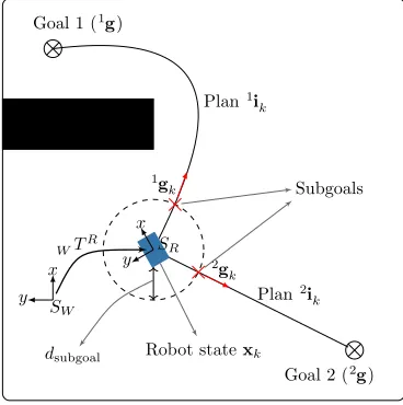
k, referred to as mgk. Subgoals are determined on each path to each defined goal, i.e. xk → mgk →mg as the furthest point, to which a straight line can be drawn from the current robot position without touching any obstacle. This definition is similar to the one proposed in [32, 33] for discrete interfaces. Sub-goals are searched for within a predefined circle around the robot with a radiusdsubgoal. The process of finding the subgoals is depicted in Fig. 3. These assumptions
Goal 1 (1g)
Goal 2 (2g)
Robot statexk
g 1
k
g 2
k Plan1i
k
Plan2i
k Subgoals
dsubgoal
y x
y x
TR W
SW
[image:7.612.335.519.66.251.2]SR
Figure 3: An example of estimating subgoals for goals 1 and 2. Subgoals in the figure are indicated by the red crosses and the black rectangle corresponds to an obstacle.
lead to the new approximation for the user model as
P(uk |mik)≈P(uk |xk,mgk).
Once the user command uk arrives, the relative orientations of the robot with respect to the computed subgoals are used to compute the approximated likelihood functionP(uk|xk,mgk) as shown in Fig. 4. For instance, when a turn left command is issued by the user, all computed subgoals which lie in the left semi-circle with respect to the robot’s heading are assigned a higher score than those which lie in the right semi-circle. The user model ignores the z-component (the altitude) of the available goals.
4.2.2. User Gaze Model
The term P(hk | mg, u0:k−1,h0:k−1,1:ni0:k) denotes the likelihood of a user’s gaze hk given the sequence of user commands u0:k−1, the previous gaze sequence
x
y
s= 0.7
s= 0.9
s= 1.0
(a) Forward
x
y
s= 1.0
s= 0.7
turn left
(b) Turn left
x
y
s= 1.0
s= 0.7
turn right
(c) Turn right
Figure 4: The user input model shown for the translational and rotational commands. Subgoals are assigned a score depending on their location relative to the robot heading (corresponds to the x-axis in the plots). The lighter the area, the lower the score, e.g. subgoals, which are located in the negative x direction and have an angle greater than 180◦ (behind the robot) get the lowest scores assigned if a forward command were issued. The shown scores are exemplary.
he/she is trying to reach on the path towards the final goal. Nonetheless, such subgoals can be accounted for by the user input model. The user gaze model can then be approximated asP(hk |mg,xk).
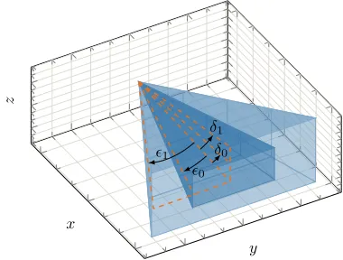
In order to computeP(hk|mg,xk), we note that the field of view of human vision is typically divided into an inner (i.e. foveal vision) and an outer (i.e. peripheral vision) part. The foveal vision corresponds to the sight area which maps on the central part of the retina with the highest receptor density and highest visual resolution. Thus, for sharp vision, one has to align the eyes/head to look directly at the point of interest. The peripheral vision, on the other hand corresponds to the remaining area of the visible field of view with lower resolution.
Inspired by these characteristics of the human vision system, we define two regions for the focus of attention. An inner region that is defined by the two angles 0 and δ0, which respectively determine the horizontal and vertical openings around the gaze direction, as depicted in Fig. 5. Similarly, the outer region can be determined by the angles 1 and δ1. With these assumptions, target goals are classified into three categories at any time instant k, according to their position with respect to the two regions of attentional focus, i.e. in the inner or outer region or out of sight. By conforming transformation, the goal locations (ignoring their relative orientation, i.e. mθ) can be defined with respect to the moving gaze frame as
g
m H= TH
W ·m Wg , (4)
whereWTH denotes the transformation matrix from the fixed world frame (W) to the moving gaze frame
x
y
z
0
1 δ0
[image:8.612.84.524.66.226.2]δ1
Figure 5: The inner and outer spatial regions of attentional focus are shown with respect to the coordinates system of the moving gaze frame.
(H).
Consequently, three conditions need to be fulfilled for a goalmto be assigned to the inner region. These are
x
m H>0 (5)
atan(m Hy , xm H)< 0 (6) atan(m Hz , xm H)< δ0 (7)
where m Hx , ym H and m Hz are the x, y and z components of the goal location in the moving gaze frame (H). Similar conditions can be derived for the outer region using the limiting angles1andδ1.
[image:8.612.333.523.322.466.2]the gaze mode as
P(hk|xk,mg)∝
a if mg lies within inner fov b if mg lies within outer fov c otherwise,
(8)
where a > b > c > 0 are constants to be chosen at design time.
4.2.3. Plans Evolution Model
The path plans evolution model denoted by P(1:nik |
g
m , u
0:k−1,h0:k−1,1:ni0:k−1) defines the likelihood that the robot currently has the path plans 1:ni
k given that the user has mg in mind, and the sequences of issued commands and gaze points and all path plans previously computed for all goals up to time instant k −1. Assuming that the plans 1:ni
k are conditionally independent of the previously issued commands and gaze points given previous path plans and the target goal, the path evolution model reduces toP(1:ni
k | mg,1:ni0:k−1). Despite this simplification, the computation of this model remains a bit tricky as it involves all plans computed to all end goals up to time instant k. In the following, a series of approximations allow to arrive at a reasonably simple model. Hereby, we consider first the path plan length, i.e. (ml
k), as an approximate sufficient statistic of the plan mi
k. This yields P(1:nlk | mg,1:nl0:k−1) as an approximation of the plan evolution model, where
l
1:n
k denotes the path plan lengths to all goals at time instant k. With this approximate statistic, only the lengths of the plans, rather than the complete path plans, need to be stored in memory in order to compute the score of the plans evolution model. With further simplification, the memory requirements are reduced to a single value. Fig. 6 shows a simple example with three different goals, and the evolution of their path plans. At each time instantk, the current and previous path plans are used to reason about the possible target goals.
As a heuristic estimate of the plan evolution model, we use the relative changes in path lengths returned by the path planner at each update to capture special trends towards (or away from) one (or more) end goals. Formally, we define ∆ml
k = l mk−ml
k−1
l m
k+C as the relative difference in length at timek for goal m, where division by zero is mitigated by the constant C ∈R+. Dividing by the current path length assures that closer goals are favored over farther ones. To account for path length differences further back in time, a weighted moving average over ∆ml
kdenoted by ∆ ˜ml
k is adopted and computed with ∆ ˜mlk=α∆mlk+ (1−α)∆ ˜ml
k−1, where 0< α <1 is a forgetting factor, and ∆ml
1= ∆ ˜ml1= 0 for allmsincex0=x1.
g
1
g
2
g
3
i
1 1
i
1 2
i
1 3
i
2 1
i
2 2
i
2 3
i
3 1
i
3 2
i
3 3
x1
x2
[image:9.612.338.517.65.207.2]x3
Figure 6: A simple example showing the evolution of trajectories towards three target goals. The plan evolution model assigns more scores to the goals whose record so far shows a trend of approach (e.g. 1gin the figure since 1l
3< l12< l11).
The values of ∆ ˜ml
k summarize approach (and depart) trends with respect to the different target goals in the environment, and thereby the plan evolution score can be approximated with
P(1:nlk| mg,1:nl0:k−1)∝f(∆ ˜mlk), (9)
where only the sequence of path plans towards goal m are used to compute f(∆ ˜mlk). This is rather a simplification, but given that P(1:nl
k | mg,1:nl0:k−1) needs to be computed for all goals in the environment, all available information from the computed path plans will be made use of. The functionf(∆ ˜ml
k) is defined as
f(∆ ˜mlk) =β1·
1−
1 exp−β2·∆ ˜mlk
+ 1
+β3,
(10)
where the parameters β1, β2 and β3 to be chosen at design time.
Intuitively, the score function in (10) favors goals whose new plans are shorter than the previously computed and among those, favors the closer end goals to the farther ones.
4.2.4. GR in Noisy Interfaces
Pk(mg|uˆ0:k,h0:k,1:ni0:k)
= X
u1:k∈Uk
Pk(mg|u0:k,uˆ0:k,h0:k,1:ni0:k)·P(u0:k|ˆu0:k,h0:k,1:ni0:k)
(1)
= X
u1:k∈Uk
Pk(mg|u0:k,h0:k,1:ni0:k)·P(u0:k|uˆ0:k)
(2)
= X
u1:k∈Uk
Pk(mg|u0:k,h0:k,1:ni0:k)· i=k Y
i=1
P(ui|ˆui)
(11)
The first simplification (1) is based on the assump-tion thatu0:k is conditionally independent ofh0:k and
i
1:n
0:k given ˆu0:k. On the other hand, (2) is based on the assumption that consequent user commands are independent of each other and only depend on the cur-rent noisy measure thereof.
The formulation in (11) means that the recognizer should keep a record of all possible hypotheses about the user input which can be traced back to the first observation received, i.e. ˆu1. The number of these hypotheses, however, grows exponentially with k, i.e.
|U|k. Therefore, in this work, we limit tracing these hypotheses to the last issued command only, which implies that the uncertainty about each command is only accounted for once. In case of SSVEP-based interaction, the probabilities P(ui | uˆi) are obtained from the interface confusion matrix which can be computed from a short training session as shown in [36]. Hereby, (11) also includes the possibility that the BCI issues a command while the user wants to be in the idle state (i.e. NOOP command). However, this is taken into consideration only in updating the posterior of the belief vector. The wrongly classified commands during the idle state propagate to the execution phase.
4.2.5. Asynchronous Posterior Updates
In absence of any additional information, e.g. user navigation preferences, the system starts with P0 =
[1/n,· · ·1/n]. The update rule in (3) can be triggered
either by the arrival of a user command or a new gaze point at the time instant k. Obviously, both triggers arrive in an asynchronous manner, and the probability that both will arrive exactly at the same time can be neglected. It is possible here for example to wait for the availability of the two signals to trigger the update synchronously. However, in this case many useful information, from which the recognizer can benefit will be lost. The other possibility is to trigger the update with every new information observed about the user. Consequently, the user input model contribution to the posterior in (3) will be ignored in case of gaze-based trigger, and the user gaze model contribution will be ignored when a new user command arrives.
In case of updates triggered by new user com-mands, a multiplication of the user input probability, the plan evolution probability and the prior followed
by a normalization step yields the posterior. Since the path evolution model is independent of the user command which triggers the update, we compute its contribution every time the robot state x changes in order to react as quickly as possible to the arrival of user commands. In the case of SSVEP-based interac-tion, uncertainty in user commands is accounted for with the formula in (11). Gaze-triggered updates are computed in a similar manner.
5. Experimental Evaluation
In order to empirically evaluate the Bayesian frame-work from Sec. 4, experiments were conducted with healthy subjects with a real and a simulated robot. This study is part of a larger project, which is approved by the Ethics Committee of the Faculty of Medicine of the Technical University of Munich (TUM).
Hereby, the performance of the GR framework is directly evaluated as the fraction of instances, at which the recognizer is able to correctly estimate the hidden user goals, while users navigate towards different goals in the remote environment. However, the predictions of the GR (i.e. the belief vectors) remain useless unless they are used in a way or another to improve interaction. Therefore, we adopted a shared control (SC) application of the belief vector, whereby when the GR module becomes confident about its belief, online modulation of the translational and rotational steps is performed so that the robot gets closer to high probable goals. The integration of an unobtrusive SC with a reliable GR system is expected to reduce the number of user commands required to accomplish navigation tasks. This way, the shared control (SC) application can provide indirect measure of the GR method reliability. Formally, the step modulation is obtained with
x=
(
xdefault if s < sthresh
s·xopt+ (1−s)·xdefault if s≥sthresh, (12)
5.1. Hypotheses
Based on the characteristics of the Bayesian inference system, we have formulated the following hypotheses. First, the integration of SC exploiting command-triggered updates of the GR into the robotic system is expected to result in a fewer number of user commands when compared to the situation when SC is disabled (H1). Second, the incorporation of gaze information, in addition to user commands, into the GR system should produce more accurate estimates about the hidden goals and consequently should result in a fewer number of user commands when SC is enabled (H2) compared to the case when the gaze information is not made use of in the GR system. Third, we expect the GR system, though mostly designed with 2D path planning for 2D navigation commands, to generalize to flat floor 3D environments, but perhaps with reduced performance. On this account, we hypothesize that comparable results, in terms of user commands required to accomplish the assigned tasks, are obtained in experiments within a 3D physical environment and a 2D simulated version thereof (H3). Fourth, BCIs typically require higher number of user commands in different application domains when compared to deterministic interfaces like keyboards. We hypothesize that the magnitude of reduction in user commands that results from the incorporation of GR into SC should differ between the keyboard and the non-deterministic BCIs (H4).
5.2. Conditions and Experimental Design
The experiments required that subjects drive a robot in a remote physical and a simulated environment and to visit a predefined subset of goal locations within these environments. We have varied the experimental setup within three factors:
(i) The type of the robot/environment used (RBT): simulated 2D (S) or physical 3D (P).
(ii) The type of the interface (IN T F C): keyboard (K) vs. SSVEP-based BCI (B).
(iii) The type of the GR-SC (SCT RL): GR is based on user commands only with SC not activated (L1), SC is applied on the basis of command-triggered belief updates only (L2) or SC on the basis of command and gaze-triggered belief updates (L3). A fully crossed design was not feasible, since the gaze (estimated with the head orientation as will be explained later) cannot be incorporated within the GR system for the 2D simulated robot/environment. Fig. 7 visualizes the resulting factorial design with the black cells referring to the infeasible conditions. The following subsections provide more details about the implementation of the different conditions.
L1
L2
L3
K
1 2B
3 4L1
L2
L3
K
5 6 7B
8 9 10 [image:11.612.330.527.65.143.2]Simulated environment (S) Physical environment(P)
Figure 7: Experimental factorial design consisting of 10 different experimental conditions. Black cells correspond to infeasible conditions.
RGB camera
3DOF neck
7DoF arm
SICK S300 safety laser scanner
Emotional head
Kinect
Processing computers and electronices
Gripper
Pressure-sensitive safety bumpers
Mobile base
Figure 8: The robot avatar. The labels shown in gray indicate robot parts irrelevant to the scope of this work.
5.3. Experimental Setup
5.3.1. Physical Robot: Fig. 8 shows the robot avatar
[image:11.612.322.532.224.433.2]obstacles in the 2D plane parallel to the floor plane (which is assumed to be a flat surface) and having a distance d= 10 cm to it. A Kinect (Microsoft, USA) camera is fixed to the robot’s chest, which is typically used in manipulation tasks to detect objects in front of the robot. Processing is done with two computers running Ubuntu 12.04 with real-time kernel patch. The Robot Operating System (ROS) [37] is used as the default interprocess communication infrastructure.
During the experiments, the robot received incre-mental commands from the user that define the direc-tion of transladirec-tion or rotadirec-tion only. These commands were translated in turn into linear and angular velocity commands which the low-level controller of the mobile base can understand. The linear velocity is denoted byν = [νx, νy]T and the angular velocity byω, which were assigned the default values: νx=νy =±0.25 m/s andω =±0.25 rad/s. The reason we chose such slow speeds is to keep a lower rate of optical flow in the visual feedback, which is known to be correlated with cybersickness [38]. A position controller, which con-tinuously received the robot’s location, made sure that the robot moved according to the received translation and rotations steps defined. The navigation stack from ROS was used for path planning and the AMCL ROS package [39] for robot’s localization.
5.3.2. Simulated Robot: For simulated robot
conditions (S), a 2D simulated version of the physical robot was constructed using stage simulator package in ROS [40]. Hereby, only the hardware components which are related to navigation were simulated, namely the robot body, the mobile base and the laser scanners.
5.3.3. Collision Avoidance Mode: The collision
avoidance behavior is realized with a velocity filter, whereby if the distance from the robot’s body to the closest obstacle in the direction of travel (r) gets less than a predefined threshold rsafe, the incoming velocity commands undergo a reduction before they get delivered to the low-level controller (i.e. the robot slows down). The actual reduction is determined in proportion to the observed distance. If the distance to the closest obstacle in the direction of travel becomes equal to a second predefined threshold 0 <
rstop < rsafe, the robot halts and any further velocity
commands which might lead the robot closer to this obstacle will be filtered out and blocked. Consequently, this means that the robot always keeps at least rstop distance to the closest obstacle. The default values are set torstop = 0.3 m and rsafe = 0.6 m during all experiments. For a wide range of applications, these values forrstopandrsafeseem reasonable, but they can be tuned online as well, if it is required that the robot gets closer to a specific obstacle (or rather a possible
target), e.g. to perform some manipulation tasks on objects located on top of a table.
5.3.4. User Interface: The robot avatar was
embedded in a remote physical or a simulated environment and received teleoperation commands from the user who conveyed his/her commands to the system with a chosen interface, namely with an SSVEP-based BCI (B) or a keyboard (K). During physical robot operation, subjects received a continuous 3D stereoscopic video stream from the ego-perspective of the robot avatar, which they viewed with the help of a head-mounted display (HMD) weighting 380 gram (Oculus VR, United States). Additionally, the user’s head movement was continuously tracked, via the built-in head tracker available in the HMD, and transmitted to the robot side to be mapped into similar movements at the robot’s neck. In the simulated environment conditions, the environment was shown on an LCD monitor. In the BCI conditions, visual stimuli were presented overlaid on the received video stream or the simulated environment, as can be seen in Figs. 9 and 10. The temporal resolution of the SSVEP-based interaction depends on the size of the EEG segment used for classifying user’s commands and the level of overlap between two consecutive segments as has been pointed out in [36]. The segment size and the temporal resolution were respectively set by default to 2 and 0.25 s. The interaction rate of the BCI (4 Hz) was chosen higher than that of the control loop (e.g. a translational command takes on average 1 s), as it was also important to provide continuous visual feedback about the performance of the interface, so that users could better predict the responsiveness of the interface. This rate mismatch was more pronounced for the keyboard-based interaction, and therefore user commands which arrived while the robot was moving were completely ignored by the interface unless they were meant to stop the robot. The SSVEP detection was based on the supervised CVARS algorithm [36].
Whereas keyboard interfaces potentially can provide a large set of commands using single buttons or combinations thereof, SSVEP-BCIs can only provide a limited set of commands. This is mainly due to the immersive nature of the application which necessitates that SSVEP stimuli to be shown overlaid on the video-stream received from the remote robot. The more stimuli are shown for display, the less will be the quality of the visual feedback. As a sensible trade-off, we fixed the number of possible commands to 4. By default, the commands move forward, turn left, turn right and stop are available to users. These commands, to which we will refer as normal mode
human-like navigation around and in the direction of the symmetry plane. Naturally, backward and sideways movements are the exceptions, not the norm [41]. In situations where the robot receives a command which gets completely blocked as to avoid collisions, the set of user commands gets automatically replaced by a second set that includes move backward, move right, and move left. The set of the new commands is referred to as the recovery mode commands. Most if not all the time, the recovery commands will be sufficient to bring the robot to a free space, where the normal mode of operation can be resumed by the user through a dedicated interface element. Adaptations to the interface were accompanied by an auditory feedback that produced the speech of “normal mode commands” or “recovery mode commands”, signaling the interface change to subjects.
5.3.5. Extraction of Gaze Direction: Typically,
humans adjust their gaze by moving both their head (or more precisely the neck) and eyes in order to bring the focus of attention to the spatial regions of interest around them. Specific to our immersive embodiment application, the user’s eye movement might not be spontaneous all the time, as it is the case in natural settings. In SSVEP-based interaction in particular, users overtly attend to one of the stimuli distributed at the sides of the display when they decide to issue a control command. Therefore, the user’s focus of attention in this work is estimated based on the head orientation only. This simplification is supported by the results in [42], which show that the head orientation contributes 70% to the overall gaze direction on average and that head orientation data alone is sufficient to accurately estimate the focus of attention.
The gaze movements of a user observing a scene can be, for the sake of simplicity, broadly separated into two classes. The first is characterized by sudden and rapid gaze movements known assaccades, and the second is characterized by a relative stability of the gaze for typically 200-600 ms [43] and is referred to as
fixations. Ignoring the contribution of eye movements to gaze direction implies that fixations in this work are approximated by the steady head orientations which last for a certain amount of time, i.e. fixations of the head rather than the gaze.
At the technical level, we define the gaze frame (H) as a moving coordinate system, whose origin is positioned at the midpoint between the robot’s eyes, x-axis is aligned with the gaze direction and z-axis parallel to the robot’s face plane and pointing upwards, i.e. from the neck to the forehead. In the following, we limit the tracking data to the yaw (Θ) and pitch (Φ) angles of head rotations, as the roll component, i.e. the head rotation around the axis of view, hardly affects
Forward
turnL
stop
turnR
Forward
turnL
stop
turnR
(a) Normal mode commands
Menu1
moveL
Back
moveR
Menu1
moveL
Back
moveR
[image:13.612.313.547.64.218.2](b) Recovery mode commands
Figure 9: SSVEP stimuli overlaid on stereoscopic images coming from the remote physical environment. Recognized user commands are typically highlighted in green. The “Menu1” command in recovery mode resumes the normal mode commands. The scene shows an example target location, where a glass bottle can be observed behind the AR marker (which is highlighted in the figure with green). Part of the robot base is visible at the bottom side of the images. The visible lens barrel distortion (at the capturing side) is counteracted by the HMD which magnifies the images it receives (i.e. pincushion distortion).
the actual gaze direction.
Figure 10: Simulated environment with SSVEP stimuli overlaid at the sides of the display. The stimuli constellation allows for intuitive interaction.
In the second stage, the sample mean of the incoming classified fixations in the yaw-pitch plane is recursively computed to determine the sample gaze mean [ ¯Θ,Φ].¯ The newly incoming fixations continuously update the old sample mean as long as their Euclidean distance to the current mean is below a certain threshold denoted by dthresh. Otherwise, i.e. if the distance is larger than dthresh, the sample mean is set to the new fixation, as shown in Fig. 11. Every time the sample mean is set anew, it gets broadcasted as a new gaze point, i.e. hk = [ ¯Θk,Φ¯k]T. With the help of this information and the available transformation tree to the system, the transformation from the fixed world frame (W) to the moving gaze frame (H), i.e. TH
W , can be easily computed.
¯ Φk
¯ Θk
¯ Θk−1
¯ Φk−1
Φ
Θ
d
thresh fnew
Figure 11: Mean gaze estimation from incoming fixation points (indicated as black crosses). When a new fixation is received, its distance to the old mean is checked against dthresh and the new mean [ ¯Θk,Φ¯k] is computed accordingly either by updating the old mean [ ¯Θk−1,Φ¯k−1], or by setting the mean to the new value.
5.3.6. Goal Recognition and Shared Control:
The GR module was active in all conditions, but its computed belief vectors were used to modulate the translational and rotational steps only in the conditions L2 and L3. The default translational and rotational steps were respectively set to δddef =
±0.25 m/command andδθdef=±π/12 rad/command. In conditions L2 andL3, the translational steps were modulated ifs(Pk)>0.3, whereas a more conservative threshold was chosen to modulate the rotational steps, i.e. s(Pk)>0.8.
The recovery mode and stop commands were excluded from the user input model as they are not typically oriented towards the final goal but rather dictated by the presence of obstacles in the robot’s surroundings. In some cases, users might need to recede away from a goal in order to avoid the immediate obstacles. For the user input model of forward commands, the inner and mid opening angles were respectively set to π/4 rad and 5π/12 rad. The corresponding scores for normal mode commands were chosen as defined in Fig. 4 and the parameterdsubgoal was set to 1.5 m.
The user gaze model was defined with the parameters 0 = δ0 = 0.1 rad, 1 = δ1 = 0.2 rad,
a= 1,b= 0.9 andc= 0.8. The parameters of the plan evolution model were set as follows: α = β1 = 0.8,
β2= 10 andβ3= 0.2, rendering msk ∈[0.2,1]∀m, k. Fig. 12 shows a block diagram of the whole robotic embodiment system for navigation which highlights the interconnections and message passing between the GR and SC blocks with other components.
5.4. Subjects
A total of 22 healthy adults (5 females) aged 27.59± 5.66 (range 20−38) with normal or corrected-to-normal vision served as paid volunteer subjects in this study.
5.5. Task
A 2D occupancy grid of the physical 3D remote environment (a cluttered laboratory space, with many desks, tables and other robots) was built using a laser-based SLAM algorithm available in ROS, i.e. the gmapping package [45]. In total, 16 different goals were manually defined on the map, e.g. at the lab doors and other salient spots like desks, and were additionally marked in the physical environment with augmented reality (AR) markers. The occupancy grid of the environment and the set of all goals are shown in Fig. 13. The same occupancy grid was used to build a simulated environment with the stage simulator package in ROS [40].
[image:14.612.87.267.474.619.2]HMD —————–
User
Gaze
Filter Goal
Recognition
Velocity Filter
Position Control Shared
Control
Map
Path Planning User
Interface
Localization Robot
ˆ uk,C
hk
Pk
,
ˆ
uk
Odometry Laser
Scan
xk
→
mg Interaction Mode
xk
[
νx ,νy
,ω
]
[ν0 x, νy0, ω0]
Occupancy Grid
xk
ak =
(δd, δθ) colli-sion?
(Θ,Φ)
Head orientation
3D stereoscopic video stream
[image:15.612.74.538.73.297.2]User Input (keyboard, SSVEP, ...) Video stream
Figure 12: System block diagram. This work focuses on the blocks in the shaded area.
[image:15.612.330.527.342.418.2]possible. The task was to drive the robot with the chosen interface and visit 4 target goals out of the available 16, where the different subjects were assigned different sets of goals. Participants were free to decide the order, in which they might visit the target goals, but they were instructed to stick to the same order in all yet-to-be-performed sessions. Since the target goals were unfamiliar to the participants, exactly as the non-target ones, glass bottles were placed besides the AR markers of the target goals (on target desks or tables) to allow the participants to recognize them from afar, especially if neighboring goals were very close. A sample screenshot from the ego-perspective of the robot in front of a target goal is shown in Fig. 9. Since doors have less ambiguity, they were only marked with the AR markers. Additionally, in the simulated environment, target goals were colored in red whereas the remaining ones were marked in green. The simulated environment for subject S1 is shown as an example in Fig. 10. A goal was considered reached if its distance to the robot became less than or equal to 0.8 m and its relative orientation with respect to the robot’s heading was less than or equal to 0.5 rad. Additionally, the goal had to be positioned within the range[−0.2,0.2] m with respect to the y-coordinate of the robot’s frame. Subjects were instructed simply to bring the robot to face each of the assigned goals. An auditory feedback signal was played back to participants when the robot arrived at any goal location. This way, we guaranteed that participants did not recede from a goal earlier (assuming they arrived) or later (assuming they did not arrive yet)
Figure 13: The environmental map was built using laser-based SLAM. The 2D poses of the 16 goals are shown, with respect to the world frame.
than they should.
5.6. Procedure
Upon their arrival at the laboratory, subjects were provided in written form, all information they needed about the course of the experiment and the different conditions they were going to perform. All participants gave their written informed consent. Participants were additionally asked to fill in a pre-questionnaire to collect some demographical data. They were additionally given a printed floor plan of the remote environment and were asked to decide upon the order in which they wanted to traverse the subset of goals consistently across conditions.
first, and the other half were assigned the physical robot conditions first. The experimental conditions were not fully randomized as switching back and forth between the simulated and the physical robot conditions involves adding significant time overhead to the already lengthy procedures. If a subject was found to spend relatively long time (i.e. around 3 min) trying to reach the first end goal in the BCI conditions, these sessions were stopped since otherwise experiments might have extended over uncomfortable time lengths to participants, let alone the effect of long recordings on the quality of the EEG setup. Prior to the actual experiments, participants were familiarized with the different system components in the physical and simulated environments, e.g. the head tracking and mapping to the robot’s head movement, 3D visual feedback and keyboard interface. In SSVEP-based interaction conditions, electrode placement and setup were done exactly as described in [36], and EEG signals were acquired with a sampling rate of 256 Hz at full DC. Two SSVEP training sessions were additionally collected during experiments with each subject. One training session preceded the simulated environment conditions with stimuli presented against a dark screen on an LCD monitor and viewed binocularly by the participants. The other session was collected immediately before the physical environment conditions. Stimuli in the latter case were presented on the HMD against a static view from the remote environment and were viewed binocularly. Training data were used to learn two linear discriminant analysis (LDA) classifiers for the CVARS scores as described in [36], which were later used in online SSVEP-based interaction conditions, i.e. conditions 3 and 4 for the first classifier and 8, 9 and 10 for the second one. The complete training sessions were used to train the LDA classifiers but the classifier confusion matrix was estimated with a 5-fold cross split of these sessions. To elicit natural behavior, participants were not informed about the existence of the recognizer or the fact that online modulation of the system parameters was active in some conditions. On the other hand, participants were instructed to pay great attention to auditory feedback signaling task completion after each visited goal and signaling the automatic entry to the recovery/normal modes of interaction. Again, when the familiarization phase of an individual subject took relatively long time, experiments were discontinued for them, as the actual experiments were predicted thereby to extend to longer times.
5.7. Performance Metrics
5.7.1. Direct Measures: Recall and precision metrics
are adopted as in [46–48] to provide direct evaluation of our GR method. Recall is defined as the fraction
of belief updates which has the true user’s end goal in the set of N-best predictions. Precision is defined as the ratio of belief updates, in which the recognizer is confident and the true goal is among the N-best predictions, to the total number of belief updates, in which the recognizer is confident. The recognizer’s confidence is defined here, as in Appendix A, by the non-uniformness metric of its belief vectors, i.e.
when s(Pk) > sthresh. Formally, let mP1:k =
{mP
1,mP2, . . .mPk}be the sequence of belief updates
during which the true user’s hidden goal is mg, recall and precision can be computed as follows
Recall =
Pk
i=1IN(mPi)
k ,
Precision(st) =
Pk
i=1IN(mPi)·IS(mPi)
Pk
i=1IS(mPi)
, (13)
where the indicator function IN(mPi) = 1 if the goal
m is among the N-best predictions and 0 otherwise and the indicator function IS(mPi) = 1 if the non-uniformness metric of the belief vector s(mP
i) > st
and 0 otherwise. Recall and precision were computed on the basis of the four belief sequences, that were obtained per subject and per experimental condition.
5.7.2. Indirect Measures: As described earlier, the
performance of the GR module can be indirectly evaluated by considering the effect of SC on the number of commands issued to complete each task. Aiming at generalizing our results with respect to the task space, each subject was assigned a different set of goals, and hence the observed number of commands per condition and subject can be affected by the varying complexity and path length of each sequence of goals. In order to correct for this, a baseline was computed for each sequence, relative to which the observed number of commands can be computed. The baseline is computed as the expected number of discrete normal mode commands needed to visit these goals in the same order which was undertaken by the individual subjects, but assuming free space. Fig. 14 illustrates the computation of the baseline number of commands with a simple example.
6. Results
6.1. Task Completion
g
1
x0
g
2
g
3 4g
θ1
θ2
θ3
θ4
θ5
θ6
θ7
θ8
l1
l2
l3
[image:17.612.332.525.62.309.2]l4
Figure 14: Baseline computation example showing 4 different goal poses visited in the order 1g,2g,3gand
g
4 starting from the initial pose x
0. The baseline number of commands is computed asP4
i=1li+Pj=8j=1θj
conditions. These two subjects, namely S1 and S3 were the first to use the system, where at this stage of the experiment, we recorded only one training session for SSVEPs using the monitor stimulation. Since theP B conditions require visual stimulation through the HMD for online interaction, it has been observed with these two subjects that the classifier learned for the monitor-based stimulation could not generalize very well to the HMD stimulation, and therefore we decided hereafter to record another training session for the HMD stimulation as described earlier in Sec. 5.5. We decided to keep the incomplete data of these two subjects in our data analysis since other conditions still compare to the procedure used for other subjects. Additionally, 3 other subjects were able to complete all the keyboard conditions, but none of the BCI’s, as the accuracies for their SSVEP detection were relatively low. The familiarization step took longer than expected with 4 subjects, and therefore experiments were discontinued with them. 1 subject felt motion sickness during the familiarization stage and decided to drop out.
[image:17.612.90.267.66.245.2]6.2. Direct Measures
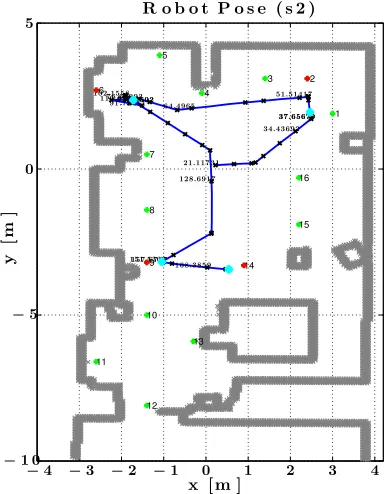
Fig. 15 shows an example of the belief vector Pk (in conditionP KL3 for subject S2) as it unfolds over time during the complete session in the form of 16 staircase plots. The rising and falling edges correspond to time instances, at which the belief vector underwent gaze or command-triggered updates. Upon arrival at any goal, the belief vector is reset. Correspondingly, Fig. 16 shows the robot’s pose during the complete session. These two figures combined can give a first insight
1 2 3
4 5
6
7
8
9
10
11
12 13
14 15 16 21.11731
34.43692 37.65679 37.65679 51.51417 64.4965
73.01692 73.01692 76.62993
91.75411
102.1558110.9771
128.6917
151.5302157.6727
168.3859
x [m ]
y
[m
]
R o b o t P o s e ( s 2 )
−4 −3 −2 −1 0 1 2 3 4
−1 0
−5
0 5
Figure 16: The complete robot’s pathxkfor subject S2 in condition P KL3. Target goals are marked in red. Additionally, points marked with cyan represent the points (in time and space), at which the user received the auditory signal signaling goal-reaching. All goals in the environment are shown with their identification numbers. The time in seconds is shown for some points along the path, wheret = 0 represents the time when the session started.
about the performance of the Bayesian GR system. Fig. 17 summarizes the results from all subjects and all finished sessions with respect to the precision and recall metrics introduced in Sec. 5.7, where precision was evaluated for different values of sthresh. The recall plots indicate that the recognizer was able to correctly estimate the user’s hidden end goals as the 1-best prediction around 40% of the time in all experimental conditions. This rate increases with increasing N, e.g. it becomes around 70% in the case of 4-best predictions. On the other hand, the increased precision observed with higher sthresh in Fig. 17(b) indicates the suitability of our proposed non-uniformness metric as a confidence measure for the recognizer.
6.3. Indirect Measures
t[s]
P
(
G
=
mg
|
u0
:
k
,
h0
:
k
,
1
:
ni0
:
k
)
B e lie f E v o lu t io n ( P h y s ic a l r o b o t , K e y b o a r d , L 3 )
0 5 0 1 0 0 1 5 0 2 0 0
0
0.2
0.4
0.6
0.8
1
1.2
G 2 G 6 G 9 G 1 4
1 2
3 4
5 6
7 8
9 1 0
1 1 1 2
1 3 1 4
[image:18.612.109.498.66.256.2]1 5 1 6
Figure 15: Belief evolution shown for subject S2 in conditionP KL3. The shaded area shows the time interval(s), during which the recovery mode was active and belief updates were not. The vertical lines correspond to the time instants when the robot arrived at a goal and are annotated accordingly.
N
R
e
c
a
ll
2 4 6 8 10 12 14 16
0 0.1
0.2
0.3
0.4
0.5
0.6
0.7
0.8
0.9
1
(Simulated robot, Keyboard, L1) (Simulated robot, Keyboard, L2) (Simulated robot, BCI, L1) (Simulated robot, BCI, L2) (Physical robot, Keyboard, L1) (Physical robot, Keyboard, L2) (Physical robot, Keyboard, L3) (Physical robot, BCI, L1) (Physical robot, BCI, L2) (Physical robot, BCI, L3)
(a) Recall for differentN-best values
sthresh
P
r
e
c
is
io
n
0 0
.1 0.2 0.3 0.4 0.5 0.6 0.7 0.8 0.9
0 0
.1
0.2 0.3 0
.4
0.5 0.6 0.7 0
.8
0.9 1
N= 1
N= 2
N= 3
N= 4
(b) Precision for differentN-best values as a function ofsthresh
Figure 17: Recall and precision of the GR module. Around 40% of the time, the GR correctly estimated the hidden user intention as the 1-best prediction. From the precision plot, it can be seen the sthreshcan be used as a confidence metric.
assigned tasks, we will hereafter refer to it as the user effort.
Our experiment in this study is a partially crossed 2×2×3 repeated-measures within-subjects factorial design (with missing data). The fact that the incorporation of gaze into the GR system is only feasible in the physical robot conditions renders it legitimate to run the analysis in two steps. Firstly, we consider the fully crossed 2×2×2 design that excludes the level (L3) in the factor SCT RL which leaves us with the levels S/P, K/B and L1/L2 of the main factors in the experiment. Secondly, we consider theL3 level within the fully crossed 2×3 design corresponding to the K/B andL1/L2/L3 levels of the IN T F C and
SCT RLmain factors, respectively.
6.3.1. Statistical Analysis of the 2×2 ×2 Design
(RBT ×IN T F C×SCT RL)
The data obtained from all subjects and all sessions (excluding L3 sessions) was analyzed using a linear mixed-effects model, where the subject factor was treated as a random factor, and the RBT, IN T F C
andSCT RLwere treated as fixed factors. To this end,
[image:18.612.65.291.323.617.2]