ISSN Online: 2165-3860 ISSN Print: 2165-3852
DOI: 10.4236/ojfd.2017.73027 Sep. 28, 2017 397 Open Journal of Fluid Dynamics
Simulation of Heat Transfer in a Tubular Pipe
Using Different Twisted Tape Inserts
Md. Moniruzzaman Bhuyan
1, Ujjwal K. Deb
2*, M. Shahriar
3, Simul Acherjee
41Department Electrical & Electronics Engineering, Southern University Bangladesh, Chittagong, Bangladesh 2Department of Mathematics, Chittagong University of Engineering & Technology, Chittagong, Bangladesh
3Department of Mechanical Engineering, Chittagong University of Engineering & Technology, Chittagong, Bangladesh 4Department of Mathematics, Narangiri Govt. High School, Chittagong, Bangladesh
Abstract
This paper performs a simulation study of the heat transfer phenomena in a tubular U-loop pipe. We have investigated the enhancement of heat transfer with mass flow in a pipe without insert, with full length and short length twisted tape inserts. The length of the pipe is approximately 2436.80 mm long with 29 mm inner and 33 mm outer diameter respectively. A constant heat flux is taken which generated the boundary layer of the pipe close to the flow-ing fluid around the boundary. The simulations are considered for the statio-nary and the time dependent module for 35 seconds with different length of inserts. The comparisons are made among the results. We observed that the transfer of heat is enhanced significantly with the increase of the length of in-serts inside the computational domain. We also found that, full length twisted tape inserts are more effective than comparing with the short length inserts and without insert.
Keywords
Heat Transfer, Non-Isothermal Flow, Tubular Pipe, Twisted Tape Inserts, Simulation
1. Introduction
The enhancement of heat transfer is the method of developing the performance of heat transfer device. There exist two methods to improve the enhancement of heat transfer. One is active method and another is passive. Both of them are used for augmentation of laminar flow heat transfer [1][2]. Till now, large number of attempts has been made to reduce the size and costs of the heat exchangers. The How to cite this paper: Bhuyan, M.M.,
Deb, U.K., Shahriar, M. and Acherjee, S. (2017) Simulation of Heat Transfer in a Tubular Pipe Using Different Twisted Tape Inserts. Open Journal of Fluid Dynamics, 7, 397-409.
https://doi.org/10.4236/ojfd.2017.73027
Received: August 7, 2017 Accepted: September 25, 2017 Published: September 28, 2017
Copyright © 2017 by authors and Scientific Research Publishing Inc. This work is licensed under the Creative Commons Attribution International License (CC BY 4.0).
DOI: 10.4236/ojfd.2017.73027 398 Open Journal of Fluid Dynamics
heat transfer augmentation techniques play a vital role for laminar flow since the heat transfer coefficient is normally low in plain tubes [3][4]. The swirl flow de-vices form an important group of passive augmentation methods where twisted tape is one of the most important members of this group [5]. Pipes with twisted tape inserts have been widely used in heat transfer technology to the heat ex-changer applications such as air-conditioning, refrigeration, automobiles, pe-trochemical industries, solar water heaters, shell and tube heat exchangers, chemical reactors power plant, process industries etc.
In the year 1896, Whitham studied about the twisted tape inserts in fire tubes of stream boilers and their effects in the flow dynamics and heat got an expected satisfactory result [6]. Kidd and Klepper, four decades ago, studied twisted tape and recommended that short length twisted tapes is more feasible for a gas cooled nuclear reactor compared with full length twisted tape [7][8]. S. K. Saha and his research group investigated heat transfer and pressure drop phenome-non for a laminar flow using twisted tape inserts and mentioned that regularly spaced twisted tape inserts shown better performance than full length twisted tape inserts for high Reynolds numbers [9]. Date and Gaintonde studied about the laminar flow in a tube using twisted tape regularly spaced inserts and pre-dicting characteristics of flow dynamics [10]. P. Promvonge, S. Eiamsa-ard et al. in the year 2007, experimented in a heat transfer augmentation in a circular tube using V-nozzle turbulator inserts and snail entry getting a significant change of heat transfer rate. They suggested that the v-nozzle turbulator inserts gives better results than that of other turbulator devices [11]. In the year 2009, S. Eiamsa-ard et al. investigated on short length twisted tape inserts and showed that it en-hances the heat transfer rate with respect to some parameters [12].
DOI: 10.4236/ojfd.2017.73027 399 Open Journal of Fluid Dynamics
recent paper, we have simulated a heat transfer model using rectangular inserts and increased the heat transfer rate than the plain tube [21].
In the above discussion we have found that numerous studies are performed about the heat transfer enhancement through the circular tube with different geometrical configurations for laminar flow. However, none of the studies report about the heat transfer augmentation and pressure drop in the tubular pipe with different twisted tape inserts. A non-isothermal flow form is well selected for the simulation. The important effort to utilize different methods is to increase the heat transfer rate by using different kinds of inserts. In the intervening time, it is estab-lished that, this way can diminish the manufacturing cost and save up the energy.
In this paper, our main goal is to present the heat transfer phenomena in a circular pipe using inserts by the Finite Element Method. The Finite Element Method (FEM)-based software COMSOL Multiphysics 4.2a version is used for this numerical study [22]. The Finite Element Method gives the more accurate results comparing with the other conventional methods. The technique devel-oped in heat transfer technology by using the FEM software has becomes popu-lar in recent years. In the case of laminar flow heat transfer by conduction, con-vection and molecular diffusion is important since there is no cross-mixing of fluids. A small amount of heat is transferred by the fluid in the laminar flow. In this simulation, we have observed a procedure of the heat transfer enhancement in a U-loop circular tube by using different twisted tape inserts inside the tube. The water is taken as fluid domain and the pipe domain is made of copper ma-terial to rationalize this simulation. A constant heat flux is considered at the sur-face of the tube.
The rest of the paper is prepared as follows: In Section 2, mathematical model is presented while governing equations of heat transfer flow in Section 3; Boundary conditions for the domain is given in Section 4; Computational domain and the mesh design of the domain are presented in Section 5; In Section 6, numerical results for the heat transfer phenomena is shown followed by conclusion in Section 7.
2. Mathematical Modeling
The aim of this study is to get better performance of the enhancement of heat transfer in a tubular U-loop pipe using different twisted tape inserts. Our model has been conscious as the geometry forms across the flow which enhances the heat transfer. The purpose of using inserts in our model is to increase layer to layer friction and presence of the inserts promotes enhanced heat transfer due to mixing.
3. Governing Equation
DOI: 10.4236/ojfd.2017.73027 400 Open Journal of Fluid Dynamics
equations which describe the flows are the Continuity equation and the Navi-er-Stokes equations given below:
( )
u 0t
ρ
ρ
∂ + ∇ ⋅ =
∂ (1)
(
)
[
]
u
u u PI F
t
ρ
∂ +ρ
⋅∇ = ∇ ⋅ − +λ
+∂ (2)
It also solves the heat transfer through a fluid and governed by the following equation:
(
)
(
)
:(
)
p
p
T T
C u T q S u p Q
t t t
ρ
ρ
ρ
τ
ρ
∂ ∂ ∂ + ⋅∇ = − ∇ ⋅ + − + ⋅∇ + ∂ ∂ ∂ (3)
where,
( )
(
)
1 2
S= ∇ + ∇u u T (4)
And Q contains heat source other than viscous heating (SI unit: W/m3). For
obtaining the heat transfer term used Fourier law of heat conduction, the con-vective heat flux; q is proportional to the temperature gradient.
i i T q K x ∂ = −
∂ (5)
where K is the thermal conductivity can be an isotropic and K becomes a tensor. The convective heat flux is given by
i ij j i T q K x ∂ = − ∂
∑
The term τ:S represents viscous heating of a fluid can be written on the
following form:
: nm mn
n m
S
τ =
∑∑
τ τThe term
(
)
p T u p t t
ρ
ρ
ρ
∂ ∂ + ⋅∇ ∂ ∂ represents a pressure work is responsible
for the heating of a fluid under adiabatic compression and for some thermo acoustic effects. By using the Equations (3) and (4) we can find
(
)
(
)
p p
T
C C u T K T Q
t
ρ
∂ +ρ
⋅∇ = −∇ ⋅ ∇ +∂ (6)
If the velocity is to zero the equation becomes
(
)
T
Cp K T Q
t
ρ ∂ − ∇ ⋅ ∇ =
∂ (7)
Convective heat transfer coefficient is obtain from
w b
Q h
T T =
− (8)
where Tw and Tb are the wall and bulk temperature, where . 2 out in b
T T
DOI: 10.4236/ojfd.2017.73027 401 Open Journal of Fluid Dynamics
Nusselt number is calculated by
hD Nu
k
= (9)
D is the diameter of the tube.
Thermal performance is calculated as
s
p
h h
η
= (10)where η is the thermal performance and hs, hp and hf are the heat transfer for
short length, plain tube and full length inserts heat transfer coefficient respec-tively.
4. Boundary Condition
In the study, the boundary conditions are assumed an uniform velocity i.e.
0.07 m sec in
u=u = at the inlet, and the temperature of the fluid is
293.15 K in
T=T = , the no slip condition i.e. u = 0 at the inner wall of the tube
and the laminar outflow at the outlet of the domain governed by the following equation:
(
)
(
T)
, 0
out t out t t out t
L ∇ − P I+µ ∇ + ∇u u = −P n ∇ =u (11)
5. Computational Domain and Meshes
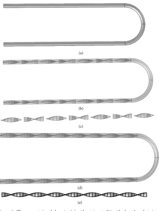
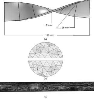
A design of computational domain without insert, with short length twisted tape inserts and full length twisted tape inserts are shown in Figures 1(a)-(e). In our simulation we have considered a typical U-loop circular tube whose length is 2436.80 mm, inner diameter 29 mm, outer diameter 33 mm. To reach a satisfac-tory computational exactness we continually change the mesh design until the outcomes obtained. The Mesh element becomes higher near the inserts positions have shown in Figures 2(a)-(c). A comparison of mesh design among different insert combinations has shown in the Table 1 and Table 2. The Table 3 showed the temperature variation of different mesh element while Table 4 showed the different parameter values of water in our simulation. As our domain length is large thus computer processor capacity becomes a significant issue for the com-putational study. The finer mesh is used along the whole comcom-putational model for numerical simulation. We used 16 GB DDR3 RAM, Intel core i7 processor based computer for our simulation.
6. Numerical Results and Discussions
DOI: 10.4236/ojfd.2017.73027 402 Open Journal of Fluid Dynamics
Figure 1. The computational domain: (a) without insert; (b) with short length twisted tape insert; (c) short length twisted tape insert; (d) with full length twisted tape inserts; (e) full length twisted tape inserts.
rate by considering the flowing fluid thus we ignored the flow heat in the solid tube.
DOI: 10.4236/ojfd.2017.73027 403 Open Journal of Fluid Dynamics
Figure 2. The computational domain: (a) short length twisted tape insert; (b) cross-section of mesh design; (c) mesh design of domain with inserts.
Table 1. Mesh elements comparison of a tubular U-loop pipe with different combination of inserts.
Property name Without insert Short length inserts Full length inserts
Tetrahedral elements 62,082 99,198 95,504
Triangular elements 16,894 30,210 31,112
Edge elements 1736 5244 5476
Vertex elements 20 412 412
Minimum element quality 0.2009 0.02766 0.04747 Average element quality 0.7332 0.6779 0.6735
Element volume ratio 0.06433 0.006154 0.006303 Mesh volume mm3 1,553,000 1,470,000 1,458,000
[image:7.595.208.540.481.621.2]DOI: 10.4236/ojfd.2017.73027 404 Open Journal of Fluid Dynamics
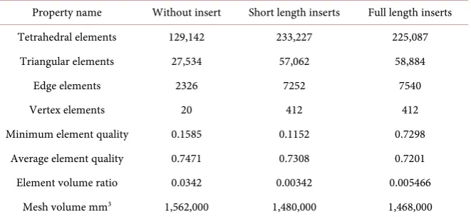
Table 2. Extra fine Mesh elements comparison of a tubular U-loop pipe with different combination of inserts.
Property name Without insert Short length inserts Full length inserts Tetrahedral elements 129,142 233,227 225,087
Triangular elements 27,534 57,062 58,884
Edge elements 2326 7252 7540
Vertex elements 20 412 412
Minimum element quality 0.1585 0.1152 0.7298
Average element quality 0.7471 0.7308 0.7201
[image:8.595.208.539.302.385.2]Element volume ratio 0.0342 0.00342 0.005466 Mesh volume mm3 1,562,000 1,480,000 1,468,000
Table 3. Temperature comparison of a tubular U-loop pipe with different combination of inserts.
Without inserts Short length twisted inserts Full length twisted inserts
Finer Mesh
temperature 368.63 496.01 502.47
Extra fine Mesh
[image:8.595.208.539.420.545.2]temperature 390.29 612 626.93
Table 4. Parameters value for the simulation.
Property name Symbol Water
Density ρ 1000 [kg/m3]
Thermal conductivity K 0.56 [W/(m·K)]
Heat capacity Cp 4.2 [J/(kg·K)]
Electrical conductivity σ 412
Ratio of specific heat γ 1.0
Dynamic viscosity µ 0.798 e−2 [Pa·s]
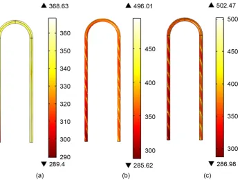
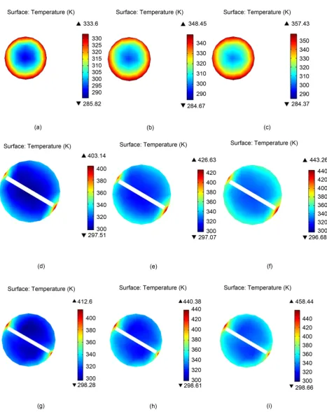
Figures 3(a)-(c) describe the above temperature.
DOI: 10.4236/ojfd.2017.73027 405 Open Journal of Fluid Dynamics
Figure 3. The computational domain of surface temperature of (a) without insert, (b) short length twisted tape inserts, and (c) full length twisted tape inserts.
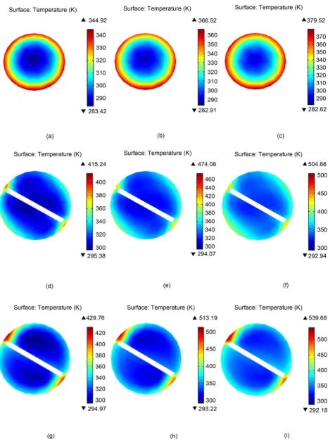
we found the temperatures for without insert after 15 sec, 25 sec, 35 sec are re-spectively 344.92 k, 366.52 k, 379.52 k and for the short length twisted tape inserts and full length twisted tape inserts temperature after 15 sec, 25 sec, 35 sec are 415.24 k, 474.08 k, 504.66 k for the short length twisted tape inserts 429.76 k, 513.19 k, 539.68 k for the full length twisted tape inserts. This is shown in the
Figures 5(a)-(c) for without insert Figures 5(d)-(f) for short length twisted tape inserts and Figures 5(g)-(i) for full length twisted tape inserts respectively. The
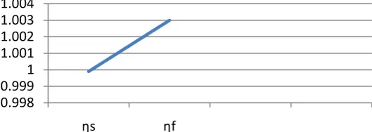
Figure 6 represents the effect of Nusselt number due to the different form of in-serts. We observed that full length inserts gives the higher Nusselt number com-pare to the other two types of inserts. From Figure 7, we found that thermal performance above unity indicates that the effect of heat transfer enhancement due to the full length twisted inserts is more dominant than the short length twisted tape inserts.
7. Conclusion
DOI: 10.4236/ojfd.2017.73027 406 Open Journal of Fluid Dynamics
[image:10.595.62.530.104.694.2]heat than the without insert. Moreover, the full length twisted tape inserts gives the better results than the short length twisted tape inserts and without insert.
DOI: 10.4236/ojfd.2017.73027 407 Open Journal of Fluid Dynamics
DOI: 10.4236/ojfd.2017.73027 408 Open Journal of Fluid Dynamics
Figure 6. Relation among different insert and Nusselt Number (Nu).
Figure 7. Thermal performance of short length and full length twisted tape inserts.
Acknowledgements
The authors gratefully acknowledge the technical supports provided by the Cen-tre of Excellence in Mathematics, Department of Mathematics, Mahidol Univer-sity, Bangkok 10400, Thailand.
References
[1] Bergles, A.E. and Rosenow, W.M. (1985) Techniques to Augment Heat Transfer Reading: Handbook of Heat Transfer Applications. McGraw-Hill, New York. [2] Bergles, A.E. and Webb, R.L. (1985) A Guide to the Literature on Convective heat
Transfer Augmentation. Advance Enhanced Heat Transfer, 43, 81-89.
[3] Hutton, D.V. (2004) Fundamental of Finite Element Analysis. McGraw Hill Com-panies, New York.
[4] Cengel, Y.A. (2006) Heat and Mass Transfer. 5th edition, McGraw Hill, New York. [5] Eiamsa-ard, S. and Promvonge, P. (2005) Enhancement of Heat Transfer in a Tube
with Regularly-Spaced Helical Tape Swirl Generators. Solar Energy, 78, 483-494. [6] Whitham, J.M. (1896) The Effects of Retarders in Fire Tubes of Stream Boilers.
Street Railway, 12, 374.
[7] Kidd Jr, G.C. (1969) Heat Transfer and Pressure Drop for Nitrogen Flowing in Tubes Containing Twisted Tapes. AIChE Journal, 15, 581-585.
https://doi.org/10.1002/aic.690150420
[8] Klepper, O.H. (1972) Heat Transfer Performance of Short Twisted Tapes. AIChE Journal, 35, 1-24. https://doi.org/10.2172/4645882
0.998 0.9991 1.001 1.002 1.003 1.004
[image:12.595.240.505.259.353.2]DOI: 10.4236/ojfd.2017.73027 409 Open Journal of Fluid Dynamics
[9] Saha, S.K., Gaitonde, U.N. and Date, A.W. (1989) Heat Transfer and Pressure Drop Characteristics of Laminar Flow in a Circular Tube Fitted with Regularly Spaced Twisted Tape Elements. Experimental Thermal Fluid Science, 2, 310-322.
[10] Date, A.W. and Gaintonde, U.N. (1990) Development of Correlations for Predicting Characteristics of Laminar Flow in a Tube Fitted with Regularly Spaced Twisted Tape Elements. Experimental Thermal Fluids Science, 3, 373-382.
[11] Eiamsa-ard, S., Woncharee, K., Eiamsa-ard, P. and Thianpong, C. (2007) Heat Transfer Enhancement in a Tube Using V-Nozzle Turbulator Inserts and Snail En-try. Experimental Thermal and Fluid Science, 32, 332-340.
[12] Eiamsa-ard, S., Thianpong, C. and Eiamsa-ard, P. (2009) Convective Heat Transfer in a Circular Tube with Short Length Twisted Tape Insert. International Commu-nication in Heat and Mass Transfer, 36, 363-371.
https://doi.org/10.1016/j.icheatmasstransfer.2009.01.006
[13] Rahimi, M., Shabanian, S.R. and Alsairafi, A.A. (2009) Experimental and CFD Stu-dies on Heat Transfer and Friction Factor Characteristics of a Tube Equipped with Modified Twisted Tape Inserts. Chemical Engineering Process, 48, 762-770.
https://doi.org/10.1016/j.cep.2008.09.007
[14] Eiamsa-ard, S., Nivesrangsan, P., Promvonge, P. and Chokphoemphun, S. (2010) Influence of Combined Non-Uniform Wire Coil and Twisted Tape Inserts on Thermal Performance Characteristics. International Communication Heat and Mass Transfer, 37, 850-856.
https://doi.org/10.1016/j.icheatmasstransfer.2010.05.012
[15] Eiamsa-ard, S., Woncharee, K., Eiamsa-ard, P. and Thianpong, C. (2010) Heat Transfer Enhancement in a Tube Using Delta-Winglet Twisted Tape Inserts. Ap-plied Thermal Engineering, 30, 310-318.
https://doi.org/10.1016/j.applthermaleng.2009.09.006
[16] Chowdhuri, M.A.K., Hossain, R.A. and Sarkar, M.A.R. (2011) An Experimental In-vestigation of Turbulent Flow Heat Transfer through Tube with Rod-Pin Insert. In-ternational Journal of Engineering, Science and Technology,3, 76-81.
[17] Fan1, A.W., Deng, J.J., Nakayoma, A. and Liu, W. (2012) Parametric Study on Turbulent Heat and Characteristics in a Circular Tube Fitted with Louvered Strip Inserts. International Journal of Heat and Mass Transfer, 55, 5205-5213.
https://doi.org/10.1016/j.ijheatmasstransfer.2012.05.023
[18] Salam, B., Biswas, S., Saha, S. and Bhuiya, M.M.K. (2013) Heat Transfer Enhance-ment in a Tube Using Rectangular Cut Twisted Tape Insert. Procedia Engineering, 56, 96-103. https://doi.org/10.1016/j.proeng.2013.03.094
[19] Hossain, S., Deb, U.K. and Rahman, K.A. (2015) Numerical Simulation of the Heat Transfer Phenomenon for a Fluid in a Circular Tube without Insert and with In-serts. International Journal of Integrated Science and Technology,1, 53-57. [20] Hossain, S., Deb, U.K. and Rahman, K.A. (2015) The Enhancement of Heat
Trans-fer in a Circular Tube with Insert and without Insert by Using the Finite Element Method. Procedia Engineering, 105, 81-88.
https://doi.org/10.1016/j.proeng.2015.05.010
[21] Bhuyan, M.M., Deb, U.K., Shahriar, M. and Acherjee, S. (2017) Simulation of Heat Transfer in a Tubular U-Loop Pipe Using the Rectangular Inserts and without In-sert. AIP Conference Proceedings, 1851, 020011.https://doi.org/10.1063/1.4984640
Submit or recommend next manuscript to SCIRP and we will provide best service for you:
Accepting pre-submission inquiries through Email, Facebook, LinkedIn, Twitter, etc. A wide selection of journals (inclusive of 9 subjects, more than 200 journals)
Providing 24-hour high-quality service User-friendly online submission system Fair and swift peer-review system
Efficient typesetting and proofreading procedure
Display of the result of downloads and visits, as well as the number of cited articles Maximum dissemination of your research work
Submit your manuscript at: http://papersubmission.scirp.org/