ISSN Online: 2165-3860 ISSN Print: 2165-3852
DOI: 10.4236/ojfd.2017.73023 Sep. 22, 2017 348 Open Journal of Fluid Dynamics
Computational Study on Aerodynamic and
Thermal Characteristics of a Hot Jet in
Parallel Flow
Merlin C. Das
1, Meribeni L. Jungio
1, N. Haritha
1, Abhilash Suryan
1*, Heuy Dong Kim
21Department of Mechanical Engineering, College of Engineering Trivandrum, Kerala, India 2Department of Mechanical Engineering, Andong National University, Andong, Korea
Abstract
The study of the migration characteristics of turbulent jets has become rele-vant as they are used in a variety of engineering devices and are encountered in combustion, chemical processes, and processes involving cooling, mixing, and drying. In several applications, especially in the case of hot streaks in gas turbines, the knowledge of mixing phenomena becomes crucial from a design perspective. The purpose of this study is to look into the characteristics of a round hot jet in a parallel air flow. A jet of hot air injected through a nozzle into a flow of cold air has been considered. Numerical simulations were car-ried out with different hot jet temperatures and two different Reynold’s num-bers, thus aiming at understanding the effect of initial conditions on the mix-ing of the jet. The temperature profiles were studied at different sections downstream of the nozzle. The results are presented in non-dimensional form.
Keywords
Turbulent Jet, Parallel Flow, Reynold’s Number, Temperature Profiles
1. Introduction
The mechanics of turbulent jets is of great interest for researchers because of the abundance of its applications. The study of turbulent jets branches into two— the study of free shear flows and the study of impinging jets. Jets impinging on a solid surface are seen in the cooling of turbine blades, drying of paper and fabric, furnace heating, tempering of glass and metal sheets, electronic chip cooling, food processing, etc. Free shear flows, on the other hand, find application in gas How to cite this paper: Das, M.C., Jungio,
M.L., Haritha, N., Suryan, A. and Kim, H.D. (2017) Computational Study on Aerodynamic and Thermal Characteristics of a Hot Jet in Parallel Flow. Open Journal of Fluid Dynamics, 7, 348-358.
https://doi.org/10.4236/ojfd.2017.73023
Received: August 1, 2017 Accepted: September 19, 2017 Published: September 22, 2017
Copyright © 2017 by authors and Scientific Research Publishing Inc. This work is licensed under the Creative Commons Attribution International License (CC BY 4.0).
DOI: 10.4236/ojfd.2017.73023 349 Open Journal of Fluid Dynamics turbines, aeronautics design, heating, cooling, ventilation and environmental fluid dynamics [1] [2].
In gas turbines, for instance, mixing characteristics of hot jets need to be stu-died. The work output of a gas turbine for a given quantity of fuel can be in-creased by increasing the temperature of the inlet gas. However, increase in the inlet temperature also means increased surface temperature of airfoils, thus making them susceptible to heat fatigue and subsequent failure. To control the high-temperature, a cooling system has to be used. Optimum design of the cooling system requires the knowledge of migration characteristics of the hot jet and of parallel air flow [3]. There have been many studies regarding impinge-ment of jets on an endplate [4] [5]. There have also been studies in the mixing of a confined jet in crossflow [6], studies investigating the effects of initial condi-tions on the characteristics of a jet [7] and on water droplets injected on an air stream [8]. The study of free shear jets has received more attention in the past decade, with several experimental studies being made in the field with specific reference to their application in gas turbine engines [9] [10] [11].
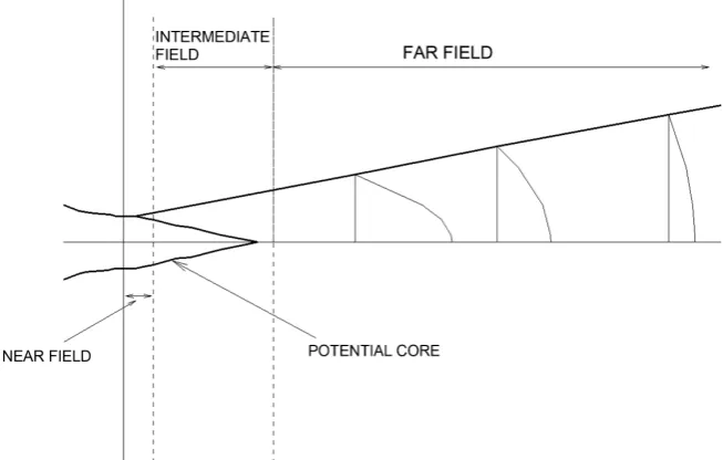
[image:2.595.211.538.494.702.2]Migration characteristics of a free shear flow may be studied by using temper-ature profiles at several transverse sections while travelling downstream in the axial direction. The flow temperature changes in the radial direction as well as in the axial direction due to the influence of the surrounding cold flow. The change in flow characteristics is different for different regions of flow as seen in Figure 1. In the initial region, the characteristics are almost the same as those at the nozzle exit. This region is called the near field, confined to within 0 ≤ z/D ≤ 6. The region where the conditions match the nozzle exit conditions is called the potential core. The potential core is the strongest in the near field and wanes downstream. The intermediate field exists in 6 ≤ z/D ≤ 30 and the far-field in z/D ≥ 30. The near-field and the intermediate-field are the regions where the
DOI: 10.4236/ojfd.2017.73023 350 Open Journal of Fluid Dynamics flow is in its developmental stage, whereas in the far-field, the flow is fully de-veloped [12] [13].
2. Experimental Details
An experimental study on the characteristics of a round hot jet [14] used the ex-perimental setup illustrated in Figure 2, consisting of a rectangular duct of width W = 1000 mm and height H = 210 mm. A nozzle of diameter D = 21 mm was centred with respect to the duct. The exit section of the nozzle was con-toured to minimise the generation of wake.
The main flow of air entered the rectangular duct at ambient temperature T∞ = 295 K and a nominal velocity of 15 m/s. The jet coming out of the nozzle was heated in the range 343 - 383 K. The velocity of the hot jet was expected to in-crease slightly as a result of density reduction due to the high-temperature.
[image:3.595.209.536.310.707.2]The value of nominal velocity was set as 15 m/s, giving Reynold’s number Re = 2.1 × 10⁴. Tests were also carried out at Re = 1 × 10⁴ obtained by either reducing
DOI: 10.4236/ojfd.2017.73023 351 Open Journal of Fluid Dynamics the nozzle diameter to 10 mm or by reducing the velocity of flow to about half of the original value.
Pressure was measured in a plane downstream of the nozzle and temperatures at various points were measured in several planes downstream of the nozzle exit.
The results were presented in terms of a normalised temperature ratio θ de-fined as hj T T T T θ ∞ ∞ − = −
where Thj was the peak temperature of the hot jet measured at the nozzle exit, T was the measured temperature at the point and T∞ was the free stream tempera-ture.
The results obtained in the study were used for the purpose of comparison with the results obtained from the numerical simulation.
3. Numerical Simulations
The governing equations for the problem are the continuity Equation (1), mo-mentum Equation (2), and energy Equation (3). The turbulence model used is the Spalart-Allmaras model (4) and the corresponding equations are given be-low: 0 j u x
ρ
∂ = ∂ (1)
0
i j ij ij
j
u u p
x ρ δ τ
∂ + − =
∂ (2)
0 0
j j i i ij
j
u e u p q u
x ρ τ
∂ + + − =
∂ (3)
(
)
1 2(
)
1 2 1 2 2 2
ˆ ˆˆ ˆ 1 ˆ ˆ ˆ
ˆ
1 b
j b i w w i b
j j j i i
c
v v v v v
u c f Sv c f f v v c
x k d σ x x x x
∂ = − − − + ∂ + ∂ + ∂ ∂
∂ ∂ ∂ ∂ ∂ (4)
Meshing and Boundary Conditions
Meshing was done using ANSYS ICEM-CFD. The inlet was divided into hot jet inlet and main flow inlet for the entry of the high-temperature jet and the low temperature main flows respectively. These inlets were specified as velocity inlets in ANSYS FLUENT, which was used to solve the problem.
The boundary conditions are shown in Figure 3. The velocity of the hot jet was specified as 15 m/s and that of the main flow as 19 m/s to counteract the change in velocity due to temperature effects. Turbulent intensity was set as 1%. Spalart-Allmaras model was used, and air was considered to be an ideal gas.
DOI: 10.4236/ojfd.2017.73023 352 Open Journal of Fluid Dynamics
Figure 3. Boundary conditions.
The nominal velocity of 15 m/s gave Reynold’s number of Re = 2.1 × 10⁴ for the hot jet. For the purpose of comparison, another set of simulations with Rey-nold’s number Re = 1 × 10⁴ were carried out by reducing the velocities to half the original values.The temperatures at sections downstream of the nozzle, namely at z/D = 2.6, 11.1 and 17.4 were found out, corresponding values of θ were calculated and the results compared with the experimental results. 3D model used for simulations are described in Figure 4(a) and Figure 4(b).
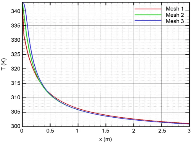
For an estimate on the numerical accuracy of the computed results, a mesh sensitivity analysis is performed. The error that can be quantified by mesh re-finement is known as the discretization error. For the quantification of the latter, an established method is recommended by the Fluids Engineering Division of ASME 38. The method is based, in principle, on the generalized Richardson extrapolation theory but has been developed into a more generalized formula-tion applicable to a wider range of practical CFD cases by Roache. The method, called grid convergence index GCI method, yields discretization error bands for the investigated variable and thus represents a sophisticated quantification of mesh dependency.
However, it is important to note that the GCI method, by definition, does not account for general modelling errors, such as the choice of boundary conditions or turbulence model; only the error due to an insufficient spatial resolution can be quantified by this method. The modelling errors may however be identified by comparing the numerical results with the experimental data.
DOI: 10.4236/ojfd.2017.73023 353 Open Journal of Fluid Dynamics
Figure 4. (a) 3D model used in simulation; (b) Enlarged view of inlet.
DOI: 10.4236/ojfd.2017.73023 354 Open Journal of Fluid Dynamics
4. Results and Discussion
4.1. Temperature Profiles at Different Axial Positions
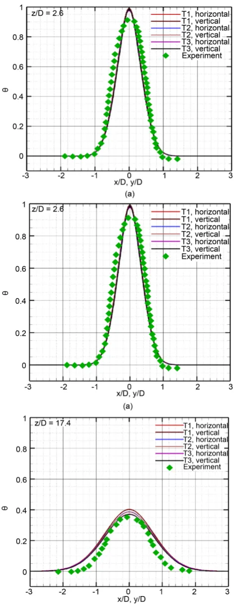
The thermal field downstream of the nozzle was investigated. Horizontal and vertical temperature profiles are presented in terms of normalized temperature ratio θ at different axial positions in Figure 6. The temperature profiles were compared to mean normalised temperature profile for different hot jet temper-atures. It can be seen that there is a good match between the experimental and numerical results. The peak values of θ are found to be slightly higher in the case of numerical simulations, probably due to the fact that in an experimental setup, there might be heat transfer from the side walls to the surroundings, which is absent in the case of numerical simulations.
The temperature profiles were compared to the mean normalised temperature profile for different hot jet temperatures. It was observed that the normalized temperature profile was the same irrespective of the initial temperature of the hot jet.
While temperature definitely decreases as one goes downstream, it can also be observed that the region of varying temperature profile tends to spread wider in downstream sections. For section z/D = 2.6, which is inside the near-field, the region of varying temperature profile is confined to −1 ≤ (x/D, y/D) ≤ 1. How-ever, in section z/D = 11.1, the temperature profile varies in −1.9 ≤ (x/D, y/D) ≤ 1.9, whereas in section z/D = 17.4, temperature profile variation is seen in −2.3 ≤ (x/D, y/D) ≤ 2.3. This is evidently an effect of the mixing and spreading of the hot jet into the parallel flow, thus reducing its own peak temperature and heat-ing up the surroundheat-ing fluid.
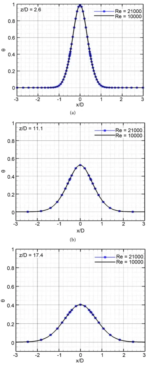
The curves corresponding to same initial temperature but in two directions (x and y) are seen to coincide perfectly, indicating symmetry of the jet. At section z/D = 2.6, the curves for different initial temperatures are almost coincident. At subsequent sections, however, the curves separate. This might be attributed to the fact that as the flow develops, heat transfer becomes dependent on the tem-perature of the jet. This is plausible, because the theories of conduction, convec-tion and radiaconvec-tion all point to heat transfer being dependent on the difference in temperatures. Interestingly, values of θ are higher for the lowest temperature, namely 343 K and lowest for the highest temperature, 383 K. This might be ex-plained based on the fact that a 383 K jet will transfer heat into a 295 K medium faster than a 343 K jet, because of the higher temperature difference. Tempera-ture profiles were also compared at jet temperaTempera-ture 343 K for two different Rey-nold’s numbers (Figure 7). The curves for Re = 21,000 and Re = 10,000 were seen to coincide exactly. This might indicate that migration characteristics are independent of Reynold’s number for high values of Re.
4.2. Axial Decay of Temperature
DOI: 10.4236/ojfd.2017.73023 355 Open Journal of Fluid Dynamics
DOI: 10.4236/ojfd.2017.73023 356 Open Journal of Fluid Dynamics (a)
(b)
[image:9.595.255.491.69.659.2](c)
DOI: 10.4236/ojfd.2017.73023 357 Open Journal of Fluid Dynamics
Figure 8. Axial decay of temperature.
It can be seen that immediately downstream of the nozzle, the normalized tem-perature matches that at the nozzle exit. The characteristics of the jet are close to those at the nozzle exit up to z/D = 6 (Abdel-Rahman, 2010). Going further downstream into the intermediate field, normalized peak temperature decreases at a faster rate. Towards the end of intermediate field where the flow approaches fully developed turbulent conditions, the slope decreases and rate of axial decay falls. Thermal diffusion of the jet is thus observed to be more intense in the re-gion of developing flow, after which, as the flow settles into fully developed state, interaction between the hot jet and the main flow decreases drastically.
5. Conclusion
A computational study has been performed on a hot jet surrounded by a parallel air flow. The temperature profiles at various sections downstream of the nozzle were studied to understand the spreading and mixing of the jet. It was observed that the normalized temperature profiles were independent of the initial tem-perature of the jet and the Reynold’s number of the flow. The cooling down of the hot jet because of the surrounding medium has also been observed in the near field and intermediate fields where the flow is still in developing stage and it has been inferred that most of the thermal diffusion of the hot jet into the sur-rounding flow happens in the developing region of the flow.
Acknowledgements
This work was supported by Advanced Research Center Program
DOI: 10.4236/ojfd.2017.73023 358 Open Journal of Fluid Dynamics
References
[1] Karimipanah, T. (1996) Turbulent jets in Confined Spaces: Application in Mixing Ventilation, Experimental and Numerical Studies. Ph.D. Thesis, Royal Institute of Technology, Sweden.
[2] Sekula, E. (2010) The Structure of Turbulent Jets: Application of Experimental and Environmental Methods. Ph.D. Thesis, Universitat Politecnica de Catalunya, Bar-celona.
[3] Zhao, Q., Wang, H., Tang, F., Zhao, X. and Xu, J. (2008) Investigation of Influen-cing Factors of Hot Streaks Migration in High Pressure Stage of a Vaneless Coun-ter-Rotating Turbine. Science in China Series E: Technological Sciences, 51, 127-144.https://doi.org/10.1007/s11431-008-0024-x
[4] Karimipanah, T. and Sandberg, M. (1994) Decay of Momentum and Velocity in an Axisymmetric Impinging Jet. Proceedings of 4th International Conference of Air Distribution in Rooms, Krakow, 15-17 June 1994, Vol. 1, 400-411.
[5] Carlomagno, G.M. and Ianiro, A. (2014) Thermo-Fluid-Dynamics of Submerged Jets Impinging at Short Nozzle-to-Plate Distance: A Review. Experimental Thermal and Fluid Science, 58, 15-35.
[6] Plesniak, M.W. and Cusano, D.M. (2005) Scalar Mixing in a Confined Rectangular Jet in Crossflow. Journal of Fluid Mechanics, 524, 1-45.
https://doi.org/10.1017/S0022112004001132
[7] Antonia, R.A. and Zhao, Q. (2001) Effect of Initial Conditions on a Circular Jet. Experiments in Fluids, 31, 319-323.https://doi.org/10.1007/s003480100289
[8] Suryan, A., Lee, J.K., Kim, D.S. and Kim, H.D. (2010) Numerical Simulation of Duct Flow with Fog Droplets. Journal of Thermal Science, 19, 533-539.
https://doi.org/10.1007/s11630-010-0420-y
[9] Jenkins, S.C. and Bogard, D.G. (2005) The Effects of the Vane and Mainstream Turbulence Level on Hot Streak Attenuation. Journal of Turbomachinery, 127, 215-221.https://doi.org/10.1115/1.1812777
[10] Jenkins, S., Varadarajan, K. and Bogard, D.G. (2004) The Effects of High Main-stream Turbulence and Turbine Vane Film Cooling on the Dispersion of a Simu-lated Hot Streak. Journal of Turbomachinery, 126, 203-211.
https://doi.org/10.1115/1.1643911
[11] Qureshi, I., Smith, A.D., Chana, K.S. and Povey, T. (2012) Effect of Temperature Nonuniformity on Heat Transfer in an Unshrouded Transonic HP Turbine: An Experimental and Computational Investigation. Journal of Turbomachinery, 134, 011005.https://doi.org/10.1115/1.4002987
[12] Abdel-Rahman, A. (2010) A Review of Effects of Initial and Boundary Conditions on Turbulent Jets. WSEAS Transactions on Fluid Mechanics, 5, 257-275.
[13] Mi, J., Xu, M. and Zhou, T. (2013) Reynolds Number Influence on Statistical Beha-viors of Turbulence in a Circular Free Jet. Physics of Fluids, 25, 075101.
https://doi.org/10.1063/1.4811403
[14] Satta, F. and Tanda, G. (2016) Aerodynamic and Thermal Characteristics of a Hot jet in Parallel Flow. Journal of Applied Fluid Mechanics, 9, 2105-2110.
Submit or recommend next manuscript to SCIRP and we will provide best service for you:
Accepting pre-submission inquiries through Email, Facebook, LinkedIn, Twitter, etc. A wide selection of journals (inclusive of 9 subjects, more than 200 journals)
Providing 24-hour high-quality service User-friendly online submission system Fair and swift peer-review system
Efficient typesetting and proofreading procedure
Display of the result of downloads and visits, as well as the number of cited articles Maximum dissemination of your research work
Submit your manuscript at: http://papersubmission.scirp.org/
![Figure 2. Schematic diagram of experimental setup showing side and top views [14].](https://thumb-us.123doks.com/thumbv2/123dok_us/173153.511219/3.595.209.536.310.707/figure-schematic-diagram-experimental-setup-showing-views.webp)