Preprint typeset in JINST style - HYPER VERSION
Point–source reconstruction with a sparse
light-sensor array for optical TPC readout
G. Rutter, M. Richards, A.J. Bennieston, Y.A. Ramachers∗
Dept. of Physics, University of Warwick, Coventry CV4 7AL, UK
ABSTRACT: A reconstruction technique for sparse array optical signal readout is introduced and applied to the generic challenge of large-area readout of a large number of point light sources. This challenge finds a prominent example in future, large volume neutrino detector studies based on liquid argon. It is concluded that the sparse array option may be ruled out for reasons of required number of channels when compared to a benchmark derived from charge readout on wire-planes. Smaller-scale detectors, however, could benefit from this technology.
KEYWORDS: Noble-liquid detectors, Optical detector readout concepts, Image reconstruction.
Contents
1. Introduction 1
2. Optical readout option 2
2.1 Charge readout benchmark 2
2.2 Sparse array readout and reconstruction algorithm 3
3. Discussion 6
4. Conclusion 7
1. Introduction
An all optical readout of charged particle tracks [1] in a time projection chamber (TPC) [2] so far has not evolved into a mainstream technology as opposed to purely charge readout on multi-wire planes. Nevertheless, for two-dimensional position resolution of interactions in a detector the advantages of optical readout were discussed early on, see [3]. The camera proposed in [3] still delivers the blueprint for large-area readout of radiation interactions in general since very few readout channels are required in order to cover a relatively large area, i.e. a cost-effective technology.
For radiation tracks, however, this method attracted rather a hybrid readout composed of an imaging device, typically a CCD camera, and a fast optical channel (or more than one) such as a photomultiplier (PMT) [1]. This technology has been deployed successfully several times for spe-cial applications [4][5][6]. Replacing PMTs with silicon photomultipliers, see discussion below, is being explored for new double-beta decay searches [7], or could potentially be deployed [8]. More recently, these hybrid optical readout methods utilised an imaging plane in form of new gaseous electron multipliers (GEMs) [9][10]. The technology demonstrated in [11] also uses a GEM opti-cal readout but replaces the CCD camera by an array of four PMTs with full area coverage, quite similar to an Anger camera [3].
Optical readout technology offers a few clear advantages compared to the vastly more abun-dant ionization charge readout:
• Excellent position resolution on large area detectors with comparable timing resolution to charge readout, see references above.
• Improved energy resolution compared to charge readout[12], in particular when combined with the charge signal [7].
• Free of electronics noise, cross-talk and mechanical challenges which increasingly plague charge readout systems as the detector size increases.
• For liquid argon as an interesting detection medium for large volume detectors intrinsic
op-tical gain is available when charge signals show none [13].
Research presented below is mainly motivated by design and development of a future (very) large volume neutrino detector based on liquid argon as an example. Successful charge readout in liquid argon has been demonstrated on the 300 tonne scale by the ICARUS epxeriment [14]. Plans for the next-generation liquid argon detectors are rather on the scale of 10 ktonne up to 100 ktonne for a (long-term future) general neutrino detector facility (combined with proton decay physics as well as astrophysics objectives). Presumably such a huge facility will have to employ an extremely cost-effective readout technology to have any chance of being realised.
In [13] a sparse array of fast light sensors was implied as a possible readout technology. This potential readout technique has been recognized in [15] and [16] for future detectors but was not examined in quantitative detail. Below, a solution to its foremost challenge is presented, i.e. a simple image reconstruction algorithm. Design conditions can therefore be given at the end of the section and conclusions given as to the viability of the sparse array as a solution to the optical readout challenge.
2. Optical readout option
The main challenge for any optical readout technology in competition with charge readout is to combine fast timing with excellent position resolution and comparable energy resolution. The hy-brid approaches cited above in the introduction achieve just that (CCD camera for spatial resolution and PMTs for timing and energy measurements). However, they require non-trivial reconstruction steps to combine these pieces of information in order to achieve a full three-dimensional raw event reconstruction. Additionally the PMT placement requirements are inconsistent with a modular large volume detector, and there is the real challenge of achieving good energy resoution when relying entirely on optical signals in the liquid [13][17]. One might argue that ideally the PMTs could be replaced with an extremely high frame-rate digital camera1which probably is the most promising way forward. However, lacking such fast cameras for now a second baseline option would be advantageous.
2.1 Charge readout benchmark
It is worthwhile at this point to comment on the existing charge readout method employed for instance by the ICARUS experiment. Undoubtedly, traditional charge readout is successful and works. It is the only existing method which demonstrated readout of charged particle tracks in large volume liquid argon detectors. The motivation to study alternative readout methods derives purely from the point of view of extrapolated costs for next-generation very large volume detectors as mentioned above.
A substantial proposal for a next-generation ICARUS experiment is published in [18], called MODULAr. More general technical discussions on a future 100 ktonne liquid argon detector are reviewed in [15]. The design in [18] is taken as the benchmark for the subsequent discussions below. It comprises large area readout of 8×8 m2with 4 m drift length as one possible design. Such a module of 358.4 tonne active mass would be measured by a total of 4000 channels using a 6 mm pitch and 3 wire planes as in ICARUS (their own estimate of each wire reading out about 200 kg of liquid argon [18] accounts only for one wire plane). In total 279 such modules would be required to raise the active mass of the detector to 100 ktonne. This results in a total of 1.116×10⁶readout channels. This rough estimate most likely overestimates the cost of the readout. Nevertheless, it serves as a conservative guideline for discussions below.
2.2 Sparse array readout and reconstruction algorithm
This technique derives from the hybrid approaches outlined above, see for example [1] and [10]. Instead of the GEM imaging plane a more robust thick GEM (THGEM [19]) imaging plane would be more beneficial. It offers better mechanical stability which would be important for a detector module area of the order of 1 m2. Likewise the realistic spatial resolution of the order of one to a few millimetre, depending on hole diameter, is fully sufficient when taking into account diffusion of charges in liquid argon, see [17] and references therein. Here it is proposed to use a sparse array of existing light sensor technology, silicon photomultipliers [20], [21], in order to take fast snaphots of charged particle tracks arriving at an imaging plane. The price to pay for such a shortcut to a full digital camera option would be the requirement of reconstruction of light source locations instead of direct imaging.
Ever since the invention of the Anger camera [3] for large area optical readout, this recon-struction requirement was present and solutions were investigated. The original solution in [3] has the disadvantage of leading to strong image distortions. The first maximum likelihood position es-timation method for this technology was published in [22]. A recent review in [23] summarises the state-of-the-art of position reconstruction using Anger-type optical readout cameras, a technology well known in medical physics. The fundamental problem of any position reconstruction method is re-iterated in [23], i.e. reconstruction of light source locations outside the circumference of the light sensor array. Otherwise, the methods based on maximum likelihood estimation work reliably and precisely, see Fig. 3 in [23].
The objective for the research conducted on the sparse array optical readout option was to deliver design conditions for imaging a 1 m2 array of light sources originating from a THGEM imaging plane, i.e. its holes. Given that sources around the perimeter of any sensor array would pose a reconstruction challenge, the condition of overlapping the outermost series of sensors with the edges of the THGEM was put in place. Subsequently several simple reconstruction techniques were tested, keeping the maximum likelihood estimator as a fall-back solution.
this article light propagates freely from the source, the THGEM holes, to the sensors and therefore displays straightforward spherical light propagation from an effective point source. This simplicity can be exploited for position reconstruction as discussed below.
It is worth pointing out that a least squares minimization algorithm would achieve the same position resolution as discussed below. The following algorithm can be considered a ’pedestrian’ version of such a minimization, which we found advantageous since every single step of the iter-ative procedure, see below, remains fully under control and can be stopped and inspected at any point.
The algorithm for position reconstruction proposed in the following is local and relies on an approximate seed point, for example from a first pass of a centre of gravity search. Subsequently,
the closest square array of 2×2 light sensors is chosen as a unit cell for the algorithm. With seed
position values x0and y0inside a thus defined unit cell of the sparse array, say detectors D1to D4,
see Fig.1, an iterative, fast converging method utilises the plain inverse square distance behaviour
of light from geometric optics. Building two light intensity ratios according to
α=I1
I2 =
r22 r21 =
x22+y22+h2
x21+y21+h2, (2.1)
whereα contains coordinates for detectors D1,2and a similarly defined ratioβ for detectors D1,3, the iteration procedure can be started. Note that I1 here is defined to be the maximum intensity measured by any detector in the array and is required to be shared by both intensity ratios, effec-tively reducing the unit cell to a triangle. The radial distancesr1,2 denote the distances from the light source location to D1,2and h is the known height of the sparse array above the imaging plane, i.e. the THGEM.
Algorithm:
A seed value, x0, for the x-coordinate of the position is passed to the algorithm. The position of the light sensors relative to each other and relative to the seed value are known, so knowledge of x1implies knowledge of x2and similarly for y-coordinates (from the constraint|y1−y2|=s, where s is the spacing or distance between sparse array sensor modules). Therefore, with the seed x-coordinate, x0, fixing x1,2for the first step, eqn. 2.1 can be solved for the only remaining unknown, y1,2, with y1and y2 related to each other by the constraint above. The new y-coordinates are then used to solve for new, updated x1,2, and, in this manner, eqn. 2.1 is used iteratively until the difference between the estimated coordinates before and after each iteration becomes small compared to other uncertainties. A loop over these steps converges quickly to the requested accuracy, here 1 mm, for a light source coordinate pair(x1,y1), see Fig. 1.
Figure 1. Left figure: Sketch of the algorithm convergence. Each arrow represents one calculational step to reconstruct the true light source position at the circle. The seed point here would be closer to D1and the first step updates the y-coordinate (vertical) to a new position further below the seed position.Right figure: Systematic errors due to the reconstruction algorithm for a full 1 m2imaging plane. The error is defined as absolute difference between true and reconstructed position.
ideal results, i.e. a more realistic treatment would worsen the results. A set of representative results is displayed in Fig.2.
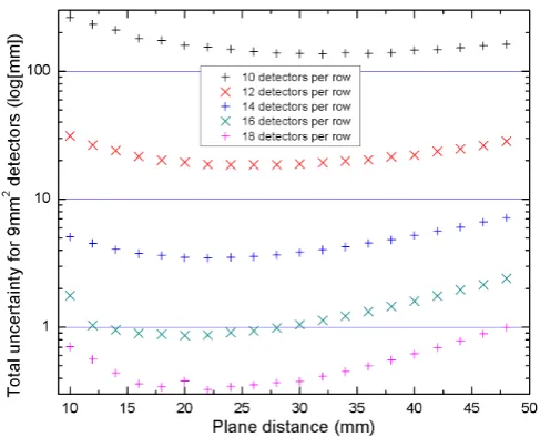
[image:6.595.171.415.442.639.2]The number of photons emitted from the simulated point source was set to 106 according to the following estimate: Specific ionization loss of the minimum ionizing particle in liquid argon
is 2.1 MeV/cm [25] resulting in just under 104 electron-ion pairs each millimetre along the track.
If such a track segment arrives at a THGEM hole of about one millimetre diameter the charges produce roughly 106photons inside the hole when taking into account the gain factor of roughly 150 [13]. Assuming commercially available SiPM sensors of 9 mm2area then yields the results in Fig. 2.
As expected for a statistical uncertainty limited spatial resolution, the curves in Fig. 2 display an optimal range for the distance between sparse array and imaging plane, i.e. too small a distance results in small effective SiPM areas which could receive photons from the source and resolution worsens. If the distance is too large, again photon statistic diminishes for each sensor and statistical uncertainties worsen the resolution. It appears that for a reasonable number of expected photons emitted from a single THGEM hole at least an array of 14×14 sensors is required to map a square metre of THGEM with a resolution of 3 to 4 mm. A 16×16 array could image down to 1 mm resolution. These results can form the basis for an informed discussion of detector design and comparison to a pure charge readout benchmark.
3. Discussion
Assuming that the benchmark set by [18] represents an upper limit, any alternative, optical readout technology would be required to improve on those readout channel numbers significantly. This might be accompanied by some restrictions in performance as long as the physics potential of the entire apparatus is not significantly compromised.
Our new reconstruction algorithm introduced above and corresponding design results enable a quantitative assessment of the sparse array option for the first time. The conclusion would have to be that the sparse array is disfavoured as a viable option compared to the traditional wire readout benchmark for large neutrino detectors, i.e. the target of this study.
The argument works as follows: Taking 196 channels as minimum requirement for a square metre imaging plane yields 12544 required readout channels for a 4 m drift module (see charge readout benchmark design above). This would be about a factor 3 more than for the wire readout. The option to take signals from the array in a row/column front-end electronics resulting in 28 instead of 196 channels per square metre would still result in about 5×10⁵ channels. However, this type of readout would seriously impact on the physics performance of each module since simultaneous hits cannot be resolved in space anymore, i.e. the actual tracking performance would cease to function.
spatial resolution of a sparse array. Likewise, large photon statistics from optical avalanche gains
in excess of 103[12] in noble gases would relax the constraints set in our case study above.
4. Conclusion
We have discussed an optical readout option for a future large volume liquid argon facility. The reconstruction algorithm as discussed above allows for the first time a quantitative assessment of the sparse array readout option and concludes that it is not viable economically for our targeted project when compared to the charge readout benchmark as defined in 2.1. In the context of the list of advantages (see introduction) of optical readout, however, light readout for tracking should be considered an important technology for future detectors. This conclusion suggests a rigorous research programme into operation of CCD or CMOS cameras inside a liquid argon environment as the next promising avenue towards an economically attractive technique for large area readout. Smaller detector proposals such as [16] might however benefit from an optical sparse array readout.
Acknowledgments
YR acknowledges part funding by the Science and Technology Facilities Council.
References
[1] P. Fonte et al., Nucl. Instr. and Meth.A283(1989) 658
[2] H.J. Hilke, Rep. Prog. Phys.73(2010) 116201
[3] H.O. Anger,Rev. Sci. Instrum.29(1958) 27
[4] U. Titt et al., Nucl. Instr. and Meth.A416(1998) 85
[5] U. Titt et al., Nucl. Instr. and Meth.A477(2002) 536
[6] M. Gai et al., 2010JINST5P12004
[7] The NEXT collaboration: F. Granena et al.,Letter of IntentarXiv:0907.4054
[8] R. Neilson et al., Nucl. Instr. and Meth.A608(2009) 68
[9] F.A.F. Fraga et al., Nucl. Instr. and Meth.A471(2001) 125
[10] L.M.S. Margato et al.,Nucl. Instr. and Meth.A535(2004) 231
[11] S.T.G. Fetal et al.,Nucl. Instr. and Meth.A581(2007) 202
[12] C.M.B. Monteiro et al.,Phys. Lett.B677(2009) 133
[13] P.K. Lightfoot, G.J. Barker, K. Mavrokoridis, Y.A. Ramachers and N.J.C. Spooner, 2009JINST4 P04002
[14] A. Menegolli, ICARUS Coll., J. Phys.: Conf. Ser. 203 (2010) 012107J. Phys., Conf. Ser.203(2010) 012107
[15] A. Marchionni,arXiv:0912.4417
[17] D.Y. Stewart et al.,2010JINST5P10005
[18] B. Baibussinov et al.,arXiv:0704.1422
[19] A. Breskin et al.,Nucl. Instr. and Meth.A598(2009) 107
[20] P.K. Lightfoot, G.J. Barker, K. Mavrokoridis, Y.A. Ramachers and N.J.C. Spooner, 2008JINST3 P10001
[21] A. Bondar et al,Nucl. Instr. and Meth.A628(2011) 364
[22] R.M. Gray and A. Macovski,IEEE Trans. Nucl. Sci.23(1976) 849
[23] H.H. Barrett et al.,IEEE Trans. Nucl. Sci.56(2009) 725
[24] A. Fabbri et al., Nucl. Nucl. Instr. and Meth. (2011) in press