th
Assessing GNSS Integrity Augmentation Techniques in
UAV Sense-and-Avoid Architectures
Roberto Sabatini1, Terry Moore2and Chris Hill2
1
School of Aerospace, Mechanical and Manufacturing Engineering RMIT University, Melbourne, VIC 3000, Australia
2
Nottingham Geospatial Institute University of Nottingham, NG7 2TU, UK
Abstract
Provision of GNSS Avionics Based Integrity Augmentation (ABIA) in Unmanned Aerial Vehicles (UAV) Sense-and-Avoid (SAA) architectures has the potential to provide an integrity-augmented SAA solution suitable for cooperative and non-cooperative scenarios where GNSS is used as the primary source of navigation and/or surveillance data (e.g, employing ADS-B). In this paper, we evaluate the opportunities offered by this integration, proposing a novel architecture that maximizes the synergies between ABIA and SAA functionalities in UAV applications. The performance of this Integrity-Augmented SAA (IAS) architecture was evaluated by simulating manned/unmanned platforms with different dynamics in representative cooperative and non-cooperative scenarios. The numerical results demonstrate that the proposed IAS architecture is capable of performing high-integrity conflict detection and resolution when GNSS is used as the primary source of navigation and/or surveillance data.
Keywords: Avionics Based Integrity Augmentation, Unmanned Aircraft, Sense-and-Avoid, Obstacle Detection, Obstacle Avoidance and Global Navigation Satellite System.
Introduction
th
safety-critical operations by continuously monitoring GNSS integrity levels and providing suitable caution and warning signals to the remote pilot or to the avionics flight control systems in order to accomplish GNSS-based mission and safety-critical tasks. This increased level of integrity could provide a pathway to support the challenging task of UAS certification for unrestricted access to commercial airspace. Although current and likely future SBAS/GBAS augmentation systems can provide significant improvement of GNSS navigation performance, a properly designed and flight certified ABIA system could play a key role in GNSS integrity augmentation for aviation safety-critical applications, including UAS SAA. Additionally, using suitable data link and data processing technologies on the ground, a certified ABIA capability could be one of the core elements of a future GNSS Space-Ground-Avionics Augmentation Network (SGAAN).
ABIA System
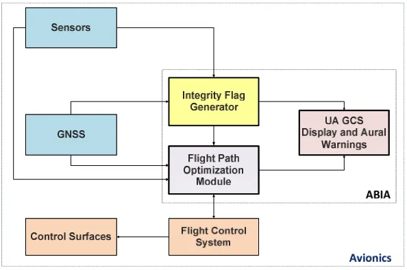
[image:2.595.150.447.344.541.2]Research activities performed previously on ABIA systems demonstrated the potential of this technology to enhance GNSS integrity performance in a variety of mission- and safety-critical applications including experimental flight test/flight inspection, precision approach and automatic landing [1-5]. Based on these results, an advanced ABIA system was developed for UAS applications (Fig. 1).
Fig. 1: ABIA system architecture for UAS applications
In this system, the on-board sensors provide information on the aircraft relevant flight parameters (navigation data, engine settings, etc.) to an Integrity Flag Generator (IFG), which is also connected to the GNSS system. Using the available data on GNSS and the relevant aircraft flight parameters, integrity signals are generated which can be sent to the UAV Ground Control Station (GCS) and/or used by a Flight Path Optimisation Module (FPOM). This system addresses both the predictive and reactive nature of GNSS integrity augmentation by producing suitable integrity flags (cautions and warnings) in case of predicted/ascertained GNSS data losses or unacceptable signal degradations exceeding the RNP specified for each phase of flight, and providing guidance information to the remote pilot/autopilot to avoid further data losses and degradations. The following definitions of Time-to-Alert (TTA) are applicable to the ABIA system [1]:
th
• ABIA Time-to-Warning (TTW): the maximum time allowed from the moment a GNSS fault resulting in an unsafe condition is detected to the moment that the ABIA system provides a warning flag to the user.
An Integrity Flag Generator (IFG) module produces the following integrity flags [1-3]:
• Caution Integrity Flag (CIF): a predictive annunciation that the GNSS data delivered to the avionics system is going to exceed the RNP thresholds specified for the current and planned flight operational tasks (GNSS alert status).
• Warning Integrity Flag (WIF): a reactive annunciation that the GNSS data delivered to the avionics system has exceeded the RNP thresholds specified for the current flight operational task (GNSS fault status).
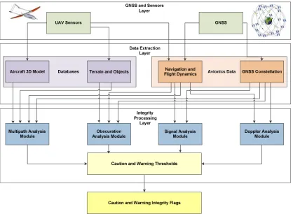
[image:3.595.90.508.301.607.2]ABIA Integrity Flag Generator
Fig. 2 shows the architecture of the IFG module and its interfaces.
Fig. 2: ABIA IFG module architecture
• The main causes of GNSS data degradation or signal losses in aviation applications were deeply analysed in [1] and are listed below:
• Antenna obscuration (i.e., obstructions from the wings, fuselage and empennage during maneuvers);
• Adverse satellite geometry, resulting in high Position Dilution of Precision (PDOP);
• Fading, resulting in reduced carrier-to-noise ratios (low C/N0);
th
• Multipath effects, leading to a reduced C/N0and to range/phase errors;
• Jamming and interference.
The ABIA IFG module is designed to provide CIF and WIF alerts in real-time (i.e., in accordance with the specified TTC and TTW requirements in all relevant flight phases) [1-5]. The GNSS and Sensors Layer (GSL) passes the aircraft Position, Velocity, Time (PVT) and attitude (Euler angles) data (from the on board Inertial Navigation Systems, Air Data Computer, etc.), GNSS data (raw measurements and PVT) and the Flight Control System (FCS) actuators data to the Data Extraction Layer (DEL). At this stage, the required Navigation and Flight Dynamics (NFD) and GNSS Constellation Data (GCD) are extracted, together with the relevant information from an aircraft Three-Dimensional Model (3DM) and from a Terrain and Objects Database (TOD). The 3DM database is a detailed geometric model of the aircraft built in a Computer Aided Three-dimensional Interactive Application (CATIA). The TOD uses a Digital Terrain Elevation Database (DTED) and additional man-made objects data to obtain a detailed map of the surfaces neighbouring the aircraft. In the Integrity Processing Layer (IPL), the Doppler Analysis Module (DAM) calculates the Doppler shift by processing the NFD and GCD inputs. The Multipath Analysis Module (MAM) processes the 3DM, TOD, GNSS Constellation Module (GCM) and A/C Navigation/Dynamics Module (ADM) inputs to determine multipath contributions from the aircraft (wings/fuselage) and from the terrain/objects close to the aircraft. The Obscuration Analysis Module (OAM) receives inputs from the 3DM, GSCS and ADS, and computes the GNSS antenna obscuration matrixes corresponding to the various aircraft manoeuvres [6]. The Signal Analysis Module (SAM) calculates the C/N0of the direct GNSS signals received by the aircraft in the presence of atmospheric propagation disturbances, as well as the applicable radio frequency interference and Jamming-to-Signal ratio (J/S) levels. The Integrity Flags Layer (IFL) uses a set of predefined CIF/WIF threshold parameters to trigger the generation of both caution and warning flags associated with antenna obscuration, Doppler shift, multipath, carrier, interference and satellite geometry degradations. The criteria for satellite-aircraft relative geometry are [1]:
• When the current A/C manoeuvre will lead to less the 4 satellite in view, the CIF shall be generated.
• When only 4 satellites are in view and one (or more) satellite(s) elevation angle is less than 10 degrees, the CIF shall be generated.
• When less than 4 satellites are in view, the WIF shall be generated.
• When only 4 satellites are in view and one (or more) satellite(s) elevation angle is less than 5 degrees, the WIF shall be generated.
From the definition of Dilution of Precision (DOP), GNSS accuracy can be expressed by [7]:
σ = DOP × σୖ (1)
where σis the standard deviation of the positioning accuracy and σୖ is the standard deviation of the satellite pseudorange measurement error. Therefore, the 1-sigma Estimated Position, Horizontal and Vertical Errors of a GNSS receiver can be calculated using the PDOP (i.e., Estimated Position Error (EPE) in 3D), the HDOP (i.e., Estimated Horizontal Error (EHE) in 2D) or the VDOP (i.e., Estimated Vertical Error (EVE)). The criteria for positioning errors are [1, 7]:
• When the Estimated Horizontal Error (EHE) exceeds the required horizontal accuracy 95% or the Estimated Vertical Error (EVE) exceeds the required vertical accuracy 95% alert requirements, the CIF shall be generated.
th
- When the Predicted Lateral Protection Level (PLPL) exceeds Lateral Alert Limit (LAL) or the Predicted Vertical Protection Limit (PVPL) exceeds the Vertical Alert Limit (VAL), the CIF shall be generated.
- When the Lateral Protection Level (LPL) exceeds the LAL or the Vertical Protection Level (VPL) exceeds the VAL, the WIF shall be generated.
• When the EHE exceeds the LAL or the EVE exceeds the VAL, the WIF shall be generated.
During the landing phase, a GNSS Landing System (GLS) has to be augmented by GBAS in order to achieve the RNP, as well as Lateral and Vertical Protection Levels (LPL and VPL). LPL/VPL is defined as the statistical error value that bounds the Lateral/Vertical Navigation System Error (NSE) with a specified level of confidence. In particular, for the case of Local Area Augmentation System (LAAS), which allows for multiple Differential Global Positioning System (DGPS) reference receivers (up to 4) to be implemented, 2 different hypotheses are formulated regarding the presence of errors in the measurements:
• H0 Hypothesis: No faults are present in the range measurements (includes both the signal and the receiver measurements) used in the ground station to compute the differential corrections;
• H1Hypothesis: A fault is present in one or more range measurements and is caused by one of the reference receivers used in the ground station.
Consequently, LPL and VPL are computed as follows:
LPL = Max {LPLୌ, LPLୌଵ} (2)
VPL = Max {VPLୌ, VPLୌଵ} (3)
The criteria for radio frequency link thresholds are:
• Multipath:
- When the Early-Late-Phase (ELP) exceeds 0.1 radians, the caution flag for multipath shall be generated [8, 9].
- When the multipath ranging error shows a sudden increase with the aircraft flying in proximity of the ground (below 448.5 metres), the warning integrity flag shall be generated.
- When the multipath ranging error exceeds 2 metres and the aircraft flies in proximity of the ground (below 500 ft AGL), the warning integrity flag shall be generated.
• Doppler:
- When the C/N0 is below 28 dB-Hz and the signal is lost, the caution integrity flag for Doppler shall be generated if the estimated acquisition time is less than the application-specific TTA requirements.
- When the C/N0 is below 28 dB-Hz and the signal is lost, the warning integrity flag for Doppler shall be generated if the estimated acquisition time exceeds the application-specific TTA requirements.
The criteria for receiver tracking thresholds are:
• When the signal tracking errors are within 5% of the maximum error budget tolerated by the receiver [7, 10, 11, 12], the CIF shall be generated.
th
• When the C/N0 is less than 27 dB-Hz or the difference between the S/N and the processing gain is less than 12 dB, the CIF shall be generated.
• When the C/N0 is less than 25 dB-Hz or the difference between the S/N and the processing gain is less than 10 dB, the WIF shall be generated.
• When the PLPL exceeds LAL or PVPL exceeds the VAL, the CIF shall be generated.
• When the LPL exceeds the LAL or the VPL exceeds the VAL, the WIF shall be generated.
Multipath integrity flags were defined using the Early-Late Phase (ELP) observable and the range error [13]. The multipath integrity flags criteria are the following:
• When the ELP exceeds 0.1 radians, the caution integrity flag shall be generated.
• When the multipath range error exceeds 1 meter, the warning integrity flag shall be generated.
The integrity flag criteria for SBAS are the following [13]:
• When VPLSBASexceeds VAL or HPLSBASexceeds HAL, the WIF shall be generated.
• When number of satellites in view is less than 7 or 8 which depends on bank angle, the CIF shall be generated.
• When number of satellites in view is less than 4, the WIF shall be generated.
The integrity flag criteria for GBAS are the following:
• When the PLPLGBAS exceeds LAL or PVPLGBAS exceeds the VAL, the CIF shall be generated.
• When the LPLGBASexceeds the LAL or the VPLGBASexceeds the VAL, the WIF shall be generated.
• When number of satellites in view is less than 5, the CIF shall be generated.
• When number of satellites in view is less than 4, the WIF shall be generated.
The ABIA system monitors the GNSS performances and gathers appropriate data to detect a departure from the nominal service state. The system reports any detected abnormal behaviour to the pilot/autopilot for action (i.e., either modify the aircraft trajectory or terminate the GNSS service). These functions are performed in a sequential manner and each function is modelled as a time-to-complete process. The cumulative sum of all four function completion times defines the time required for their associated integrity assurance process to respond to a navigation service failure. The response model provides the overall time-to-complete by considering the times required for monitoring, detecting, reporting and reacting (i.e., computing and commanding an optimised trajectory free from GNSS data degradations) and is given by [1, 14]:
Δt୰ୣୱ୮୭୬ୢ = Δt୫ ୭୬୧୲୭୰+ Δtୢୣ୲ୣୡ୲+Δt୰ୣ୮୭୰୲+ Δt୰ୣୟୡ୲ (4)
ABIA/SAA Integration
th
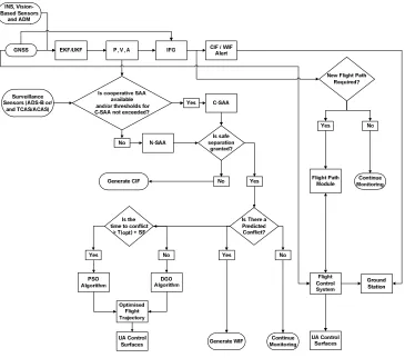
[image:7.595.118.483.249.571.2]process starts when the CIF is generated. Differential Geometry (DG) or Pseudospectral (PS) optimisations techniques are used to generate a set of optimal trajectory solutions free of near mid-air conflicts and integrity degradations. The selection of PSO or DGO is based on the available time horizons for the ABIA and SAA processes. The time to conflict is compared with that of the time taken for the optimisation and maneuver execution processes. The Frenet-Serret equations are used to describe host UAV/intruder relative motion [16] and a minimum separation distance is defined taking into account the combined navigation/tracking uncertainty volume. If the distance between the UAV and the moving intruder is or will be less than the separation distance at a specific time interval, then a conflict condition is established. Time and fuel are used as criteria in the cost functional (applying different weightings to obtain a set of feasible solutions), the dynamic model is used as the dynamic constraint, and satellite elevation criteria are used as path constraints.
Fig. 3: ABIA/SAA integrated architecture.
The selection of the optimal trajectory from the generated set of safe trajectories is performed is based on minimisation of the following cost function [17, 18]:
J = w୲∙ tୗ+ w∫[SFC ∙ T(t)]dt − wୢ∙ D୫ ୧୬−w୧ୢ∙ ∫D(t)dt (5)
where D(t) is the estimated distance of the generated avoidance trajectory points from the avoidance volume associated with the obstacle, D୫ ୧୬= min[D(t)] is the estimated minimum distance of the avoidance trajectory from the avoidance volume,tୗ = t|ୈౣ is the time at
which the safe avoidance condition is successfully attained, SFC [୩
∙ s] is the specific fuel
th
considering the cases where no WIF is generated following the raise of a CIF. The FAR is given by:
FAR =୭୲ୟ୪ୢ୳୰ୟ୲୧୭୬୭ୱ୧୫ ୳୪ୟ୲୧୭୬୭୲ୟ୪ୟ୪ୱୣୟ୪ୟ୰୫ ୱ (6)
The Detection Rate (DR) is obtained as (1-FAR).
Simulation Cases
A number of simulation case studies were performed to evaluate the performance of the ABIA and integrated ABIA/SAA systems. A GNSS Constellation Simulator (GSCS) was developed to calculate GNSS satellite position and velocity in the Earth-Centred Earth-Fixed (ECEF) reference frame and to obtain satellite visibility data from any point along the aircraft flight trajectory. The GSCS was implemented in MATLAB®to simulate both GPS and GALILEO constellations. The satellite position and velocity were calculated from the Kepler's laws of orbital motion using either the YUMA or SEM almanac data [19, 20] for GPS and a standard Walker constellation (27/3/1), which means 27 satellites in three Medium Earth Orbit (MEO) planes with 1 active spare satellite per orbital plane. The selected ABIA/SAA host platform was the AEROSONDE UAV and various geometric parameters were extracted from the literature to draw a detailed 3-D model of this aircraft [21-23]. The integration of ABIA into an existing UAV SAA architecture was studied in various C-SAA and N-SAA scenarios. In all test cases, an avoidance volume (sum of navigation and tracking errors) was generated by the SAA system [17]. PS or DG optimisation techniques were used to generate the new (optimal) trajectory based on the available time to conflict (i.e., host entering the avoidance volume). The avoidance trajectory was initiated by the SAA system when the probability of collision exceeded the required threshold value. Time, fuel, distance and integral distance were used in the cost functional, the UAV 3-DOF dynamic model was used as dynamic constraint, and the minimum elevation criteria as path constraint for both optimisation techniques. Boundary conditions were set from the values of the flight parameters at the first CIF epoch. Fig. 4 illustrates the C-SAA test scenario where three AEROSONDE UAVs (1 ABIA host platform and 1 intruder) are on a head-on collision with two at 90off track on the same Flight Level (FL) and the third UAV is descending. The risk of collision is detected and the conflict is resolved. The host UAV platform equipped with ABIA/SAA is able to generate an avoidance trajectory, which is free from CIF/WIF occurrences. As depicted in Fig. 4, the host UAV SAA avoidance trajectory and the ABIA/SAA avoidance trajectory have a different rejoin point on the original track. For clarity, three different points are shown on the ABIA/SAA host platform trajectory.
• SAA Break-off Point: The point where the host UAV initiates the avoidance trajectory (commanded by the SAA system). The cost function criteria adopted in this case is minimum time.
• SAA Safe Manoeuvring Point: The point where the host UAV can manoeuvre safely (any manoeuvre within its operational flight envelope) has 0 ROC. From this point onwards the SAA cost function criteria switches to minimum time and minimum fuel to get back on the original (desired) track.
th
SAA Break-off Point
SAA Safe Manoeuvring Point
ABIA Re-join Point
Host Platform ABIA/DAA
[image:9.595.129.470.94.280.2]Intruder Platform
Fig. 4: 3 UAV (90º and descent) collision cooperative SAA scenario
[image:9.595.140.457.366.445.2]The horizontal separation obtained in this case with respect to one of the intruders is shown in Fig. 5.
[image:9.595.124.475.526.750.2]Fig. 5: Obtained horizontal separation
Fig. 6 illustrates the N-SAA test scenario where the AEROSONDE UAV (ABIA/SAA host platform) is flying straight and level while an A320 is in a descending phase.
Host Platform ABIA/SAA
Intruder Platform
th
[image:10.595.133.466.100.186.2]The horizontal separation obtained is illustrated in Fig. 7.
Fig. 7: Obtained horizontal separation
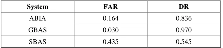
The ABIA IFG module is capable of generating integrity flags to provide both caution and warning signals when GNSS signals are degraded or lost. After the integrity caution flag is generated, the time available for the pilot/autopilot to react (before the integrity event is detected and the warning flag is generated), is at least 2 seconds [2, 3]. This TTC can support safety-critical tasks including GLS curved/segmented precision approach and automatic landing applications. In the C-SAA and N-SAA scenarios investigated and in the dynamic conditions explored, all near mid-air collision threats were successfully avoided by implementing adequate trajectory optimisation algorithms. The FAR and DR obtained for all the flight phases of the UAV with an on-board ABIA, GBAS and ABAS are listed in Table 1.
Table 1: FAR and DR
System FAR DR
ABIA 0.164 0.836
GBAS 0.030 0.970
SBAS 0.435 0.545
These results confirm that ABIA contributes to providing an integrity augmented SAA solution in cooperative and non-cooperative scenarios that is well suited for an extension of the current GBAS/SBAS augmentation network in a variety of mission- and safety-critical applications. This provides foundations for the development of a future SGAAN architecture meeting the requirements for manned and unmanned aircraft separation maintenance and collision avoidance tasks.
Conclusion
The synergies between a GNSS ABIA system and a novel UAS SAA architecture for cooperative and non-cooperative applications were explored. The integration of ABIA with SAA leads to an Integrity Augmented SAA solution, which can potentially support the safe and unrestricted access of UAS to commercial airspace. The trajectory optimization problem was tackled using both DG and PS techniques, and the real-time capability of the FPOM was verified. Simulation case studies were performed for the ABIA IFG module, IFG/FPOM modules and ABIA/SAA integration. From the results of the simulation activity, the following conclusions are drawn:
[image:10.595.108.490.396.479.2]th
• After the CIF is generated, the time available for the pilot/autopilot to react before the WIF is generated, is sufficient for safety-critical tasks including GLS curved/segmented approach and automatic landing applications.
• Data analysis shows that the ABIA system can provide the level of integrity required for CAT-IIIC precision approach, which are currently unavailable with LAAS.
• The ABIA integration into an existing UAV SAA architecture proved that all near mid-air collision threats were successfully avoided by implementing suitable trajectory optimisation algorithms.
• The proposed ABIA/SAA integration architecture is capable of achieving adequate performance by avoiding critical satellite data losses while fulfilling the separation requirements set for SAA.
Objectives for future work include the investigation and comparison of different types of avionics sensor technologies and their potential to support the design of robust ABAS/ABIA architectures for manned aircraft and UAVs. A possible extension of the ABAS/ABIA concepts to the Aeronautical Data Link (ADL) application domain and investigation of ABIA Line-of-Sight (LOS) and Beyond-Line-of-Sight (BLOS) communication interfaces for UAS applications is also being considered. Additionally, the ABIA evolutions for Next Generation Flight Management System (NG-FMS) applications [24-27] including trajectory optimization for future CNS+A systems, 4D trajectory intent based operations and NG-FMS/ABIA integration are currently being investigated. Finally, a study of the possible applications of ABAS/ABIA concepts to advanced mission planning and incident/accident investigation is being conducted.
References
1. Sabatini, R., Moore, T. and Hill, C., “Avionics-Based GNSS Integrity Augmentation for Unmanned Aerial Systems Sense-and-Avoid”, Proceedings of 26th International Technical Meeting of the Satellite Division of the Institute of Navigation: ION GNSS+ 2014, Tampa, Florida, USA, 2014.
2. Sabatini, R., Moore, T. and Hill, C., “A New Avionics Based GNSS Integrity Augmentation System: Part 1 – Fundamentals”, Journal of Navigation, Vol. 66, No. 3, May 2013, pp. 363-383. DOI: 10.1017/S0373463313000027
3. Sabatini, R., Moore, T. and Hill, C., “A New Avionics Based GNSS Integrity Augmentation System: Part 2 – Integrity Flags”, Journal of Navigation, Vol. 66, No. 4, June 2013, pp. 511-522. DOI: 10.1017/S0373463313000143
4. Sabatini, R., Moore, T. and Hill, C., “A Novel GNSS Integrity Augmentation System for Civil and Military Aircraft”, International Journal of Mechanical, Aerospace, Industrial
and Mechatronics Engineering, Vol. 7, No. 12, International Science Index, December
2013, pp. 1433-1449.
5. Sabatini, R., Moore, T. and Hill, C., “GNSS Avionics-Based Integrity Augmentation for RPAS Sense-and-Avoid Applications”, Proceedings of the Fourth Australasian
Unmanned Systems Conference, December 2014. DOI: 10.13140/2.1.3268.5120
6. Parkinson, B.W. and Spilker, J.J., “Global Positioning System: Theory and Applications -Volume I”,AIAA - Progress in Astronautics and Aeronautics, 1996.
7. Kaplan, E.D. and Hegarty, C.J., “Understanding GPS: Principles and Applications”, Artech House, Second Edition, 2006.
th
(Australia), 2010. Available at http://www.gmat.unsw.edu.au/snap/staff/omer _mubarak.htm.
9. Mubarak, O.M. and Dempster, A.G., “Statistical Analysis of Early Late Phase for Multipath Detection”,International Global Navigation Satellite Systems Society (IGNSS)
Symposium 2009, Gold Coast, Australia, December 2009.
10. Ward, P., “Using a GPS Receiver Monte Carlo Simulator to Predict RF Interference Performance”, Proceedings of the 10th International Technical Meeting of The Satellite
Division of The Institute of Navigation, Kansas City, USA, September 1997,
pp.1473–1482.
11. Ward, P., “GPS Receiver RF Interference Monitoring, Mitigation, and Analysis Techniques”, NAVIGATION, Journal of the Institute of Navigation, Vol. 41, No. 4 (Winter), 1994-95, pp. 367-391.
12. Braasch, M.S., “On the Characterization of Multipath Errors in Satellite-based Precision Approach and Landing Systems”, College of Engineering and Technology, Ohio University, June 1992.
13. Kang, L., “Assessment of Space, Ground and Aircraft Based Augmentation Systems Performance”, MSc Thesis, School of Engineering, Cranfield University, 2011-2012. 14. Leasure, S.L., Parrott, D. and Thomas, J., “HighDynamic StandAlone GPS Navigation
-the Limits of a Reversionary Mode”, Proceedings of Fourth International Technical
Meeting of the Satellite Division of The Institute of Navigation, ION GPS, September
1991, pp. 453-458.
15. Ramasamy, S., Sabatini R. and Gardi, A., “Avionics Sensor Fusion for Small Size Unmanned Aircraft Sense-and-Avoid”,Paper presented at IEEE Workshop on Metrology
for Aerospace, Benevento, Italy, May 2014, pp. 271-276. DOI:
10.1109/MetroAeroSpace.2014. 6865933
16. Rodriguez P., Sabatini R., Gardi A. and Ramasamy S., “A Novel System for Non-Cooperative UAV Sense-and-Avoid”, Proceedings of European Navigation Conference 2013, Vienna, Austria, April 2013.
17. Sabatini, R., Gardi, A. and Ramasamy, S., “A Laser Obstacle Detection and Avoidance System for Unmanned Aircraft Sense-and-Avoid”, Applied Mechanics and Materials, Vol. 629, Trans Tech Publications, Switzerland, 2014, pp. 355-360. DOI: 10.4028/www.scienti fic.net/AMM.629.355.
18. Sabatini, R. Gardi, A. and Richardson, M.A. “LIDAR Obstacle Warning and Avoidance System for Unmanned Aircraft”, International Journal of Mechanical, Aerospace,
Industrial and Mechatronics Engineering, Vol. 8, No. 4, International Science Index,
April 2014, pp. 62-73.
19. YUMA GPS Almanacs. Available at: http://www.celestrak.com/GPS/almanac/Yuma/ definition.asp.
20. SEM GPS Almanacs. Available at: http://www.celestrak.com/GPS/almanac/SEM/ definition.asp.
21. Sabatini, R., Richardson, M.A., Bartel, C., Kaharkar, A., Shaid, T., Rodriguez L. and Ramasamy, S., “A Low-cost Vision Based Navigation System for Small Size Unmanned Aerial Vehicle Applications”,Journal of Aeronautics and Aerospace Engineering, Vol. 2, No. 3, May 2013. DOI: 10.4172/2168-9792.1000110.
22. Sabatini, R., Kaharkar, A., Bartel C. and Shaid, T., “Carrier-phase GNSS Attitude Determination and Control for Small UAV Applications”, Journal of Aeronautics and
Aerospace Engineering, Vol. 2, No. 4, July 2013. DOI: 10.4172/2168-9792.1000115.
th
ARPN Journal of Systems and Software, ISSN: 2222-9833, Vol. 2, Issue 11, December
2012, pp. 297-322.
24. Sabatini, R., Liu, Y., Ridder, K. De, Gardi, A., Ramasamy, S., Zammit-Mangion, D. and Rodriguez, L., “ENDEAVOUR Project – Novel Avionics and ATM Systems for SESAR and NextGen”, Paper presented at the Conference Avionics Europe 2013 – Tackling the
Challenges in Avionics: Single Sky Many Platforms, Munich (Germany), February 2013.
25. Ramasamy, S., Sabatini, R., Gardi A. and Kistan, T., “Next Generation Flight Management System for Real-Time Trajectory Based Operations”, Applied Mechanics
and Materials, Vol. 629, Trans Tech Publications, Switzerland, 2014, pp. 344-349.
DOI:10.4028/www.scientific.net/AMM.629.344.
26. Ramasamy, S., Sangam, M., Sabatini R. and Gardi, A., “Flight Management System for Unmanned Reusable Space Vehicle Atmospheric and Re-entry Trajectory Optimisation”,
Applied Mechanics and Materials, Vol. 629, Trans Tech Publications, Switzerland, 2014,
pp. 304-309. DOI: 10.4028/www.scientific.net/AMM.629.304.
27. Gardi, A., Sabatini, R., Ramasamy, S. and Kistan, T., “Real-Time Trajectory Optimisation Models for Next Generation Air Traffic Management Systems”, Applied
Mechanics and Materials, Vol. 629, Trans Tech Publications, Switzerland, 2014, pp.