Performance Comparison of Three Types of Sensor
Matrices for Indoor Multi-Robot Localization
Israa Subri Alfurati
Electrical Engineering Dept. University of Basrah
Basrah, Iraq
Abdulmuttalib T. Rashid
Electrical Engineering Dept. University of Basrah
Basrah, Iraq
ABSTRACT
In this paper, a study for choosing a suitable system for indoor multi-robot localization is introduced. This work is based on design an environment with pair of sensors, one is fixed on each robot to work as a receiver and the other is arranged in a matrix and distributed uniformly in the environment to work as a transmitter. The coordinate axis of any robot is known when it is receiver sensor detect any transmitter sensor because any one of these sensors has a knowledge coordinate axis. Three types of sensor pairs are used: light emitting diode LEDs (light transmitter) with light dependent resistor LDR (light receiver), radio frequency identification RFID tag (transmitter) with RFID reader (receiver) and infrared sensor pair IR (transmitter and receiver). Practical circuits for these sensor types are built and tested and suitable results are obtained. The performance of these sensors are compared to choose the cheapest and the most appropriate one for indoor localization.
General Terms
Localization, Multi-robot system.
Keywords
Localization; light emitting diode; Light dependent resistor; Radio frequency identification; Infrared sensor.
1.
INTRODUCTION
Indoor localization of multi-robot system is one of main issues on service robot area. Various sensor systems like ultra-sonic, distance IR sensor, laser range finder (LRF), RF range systems such as UWB and chirp spread-spectrum (CSS), and vision have been applied to solve localization problem [1- 4]. Due to the low cost and scalability, RFID system can be the solution. Another solution may be an indoor localization grid based on a semiconductor light emitting diode LEDs. Also IR transmitter and receiver can be used. It is being realized that LED will be the desired lighting source in future. The RFID system that used to localize mobile robot in distributed tags on the floor is called RFID Tag floor localization system [4]. The accuracy of localization can be increased by combine the RFID and the vision systems [5]. This system combines the reading of the RFID reader that fixed on a mobile robot and check the signals from the RFID tags to localize the robot with respect to universal position. After determining the global position of the robot, the feature matching can be used to checking the local position of it in a predetermined global position [5].
A robotic cluster matching algorithm is introduced for multi-robot localization. The localization problem is addressed in two stages: in the first stage, it is assumed that the absolute positions of some robots are known (from the distance IR
sensor), and in the second stage, relative orientation information is assumed to be available (from infrared sensor on robots) [6]. This system has some drawback in the localization of the mobile robot because it needs sufficient time to compute the current location of the robot. Another algorithm is designed with two beacons to scan multi-color objects using long distance IR sensors to estimate their absolute locations [7]. These two beacon nodes are placed at two corners of the environment. The recognition is estimated by matching the locations of each object with respect to the two beacons. A look-up table that contains the distances information about different color objects is used to convert the reading of the long-distance IR sensor from voltage to distance units.
In wireless sensor networks (WSN), sensors maybe used for communication, distance or angle measurements, tracking, obstacle detection, routing …etc. [8-9]. The accuracy and inexpensiveness of infrared (IR) sensors make it very suitable choice for being used in distance measuring [10]. Using sensor networks instead of GPS makes indoor localization possible. In the future, an increase in the applications that satisfy location information requirements are expected, such as navigation systems and target tracking systems in office buildings or in supermarkets [11]. A mobile sensor network is composed of a distributed collection of nodes, each of which has sensing, computation, communication and locomotion capabilities [12].
In this paper the localization is based on design a system with pair of sensors: the first one is fixed on the robot and the other is arranged in an array and distributed uniformly in the system. Three types of sensor pairs are used: LEDs with LDR, RFID tag with RFID reader and IR sensor pair. The rest of the paper is organized as follows: Section 2 explains the system description, the experimental results shown in section 3, and finally section 4 discuss the results.
2.
SYSTEM DESCRIPTION
This section includes description, the electronic circuits, and the schematic diagrams of three types of sensors that can be used for robots localization. These sensors are the LEDs with LDR pair, RFID tag with RFID reader pair and IR transmitter and receiver pair. One sensor of each sensor pair is fixed on a robot to work as a receiver and the other is arranged in an array and distributed uniformly in the environment to work as a transmitter.
2.1 LED with LDR pair
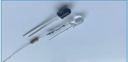
suitable current is applied to the leads) [13]. The LED technology is preferred over the other lamps because LED lamp saves the energy and it has a long life. Different colors of LEDs are available as shown in Fig. 1.
Fig. 1. The light emitting diodes with different colors.
A light dependent resistor (Fig. 2) is a low cost and very simple device that used as a light sensor. This device is used if there is a necessary to sense the presence and absence of light and it applications are mainly include burglar alarm, street lights and light intensity meters circuits. Its resistance varies according to the amount of light falling on its surface. When the LDR detect darkness light its resistance will be decreased elsewhere its increased [14].
Fig. 2. The light dependent resistor LDR
Each robot in the localization environment is equipped by one LDR sensor to work as a light sensor and several LED sensors which distributed uniformly in an array on the environment to work as light sources. The coordinate axis of each LED sensor known according to it is location in the array. The principle of the LED turn on is depend on the algorithm that used to help in robots localization. Any robot detects the light of any LED that means the robot has the same coordinate axis of that LED.
[image:2.595.322.541.248.355.2]To study the performances of this localization experiment, two slide parts are used as shown in Fig. 3. The first one is the lower part with 4.5 cm * 12 cm dimension. This part has 3 * 5 slots for fixed the array of LEDs. The second part in the experiment is the upper slide part with 3 cm * 4 cm dimension. This part has 3 slots for fixed the LDR.
Fig. 3. Two slide parts for fixing the LEDs and the LDR sensors in the first localization experiment.
2.2 IR transmitter and receiver
The second experiment of multi-robot localization depends on using the infrared IR transmitter and receiver pair as shown in Fig. 4. An IR Transmitter LED is simply emit a light with wavelength about 760 nm. It made up of GaAs (Gallium Arsenide) that emits the infrared radiation while the IR photodiode (receiver) is just the detector, which is sensitive to the same wavelength of the IR light that emitted by the IR LED. When IR light falls on the photodiode, the output voltages and the resistances will changed in corresponding to the magnitude of the received IR light. A good example of these sensor is DVD players and all different types of remote control TVs.
Fig. 4. The infrared sensor pair (transmitter and receiver).
IR sensors are cheap as compared with the other sensors and can be used for most indoor applications where no important ambient Infrared light is present [15].
Each robot in the localization environment is equipped by one IR receiver to work as an infrared sensor and several IR transmitters which distributed uniformly in an array on the environment to work as infrared sources. The coordinate axis of each IR transmitter and the principle of the IR turn on is used the same algorithm that used in the first experiment to help in robots localization. Any robot detects the IR radiation of any IR transmitter that means the robot has the same coordinate axis of that sensor. To study the performances of this localization experiment, the same two slide parts are used in last experiment (Fig. 3) also used in this experiment. The lower part is used to fix the array of IR transmitters and the upper part is used to fix the IR receiver sensor.
2.3 RFID Tag with Reader
[image:2.595.63.274.365.465.2]Radio frequency Identification (RFID) is a wireless technology that uses radio waves to automatically identify items or people (Fig. 5).
[image:2.595.323.536.635.732.2]This system consists of three major components: a reader (or interrogator) which is responsible for sending the reader signals to an RFID tag, the tag (or transponder) that contains the identification code and the third part is the reader that connect to the host computer as shown in Fig. 6 [16].
Fig.6. Illustration of RFID Tag and Reader operations.
RFID techniques are gradually promising in the body sensor network or for the Internet of Thing (IOT) applications since it can be position the location of a human body [17].
[image:3.595.55.280.134.234.2]In this experiment, each robot is equipped by one RFID reader. This reader has a recognition range in which tags are presupposed to be read in that range. According to the sensing range of the RFID reader the RFID tags are distributed uniformly in an array on the environment to work as identification points. The coordinate axis of each RFID tag is known so that when the robot detects the identity number of any RFID tag that means the robot has the same coordinate axis of that tag. To study the performances of this localization experiment, two separated parts are used for this purpose. The lower part is used to fix the array of the RFID tags as shown in Fig. 7. This part has two types of arrays to produce different distances among the RFID tags.
Fig .7. Different types for the lower part of the RFID localization system (5*5 holes) and (3*3 holes).
[image:3.595.317.546.409.692.2]The second one is the upper part with 4 cm width and 6 cm long which used to fix the RFID reader as shown in Fig. 8. This part has 4 screw passed through 4 slot onto the lower part to produces the ability to change the height. The experiments were done by choosing different position for the RFID reader onto the lower section and calculate the minimum and maximum sensing range between the RFID reader and the RFID tag.
Fig .8. The fixing of the RFID Reader on the upper part of the experiment board.
3.
EXPERIMENTAL RESULTS
3.1 LED & LDR Experiments
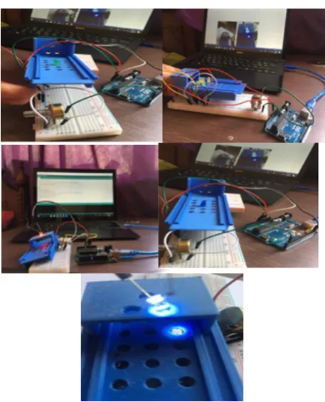
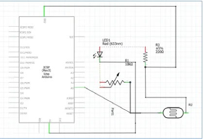
This part includes three experiments applied on the LED and LDR pair: the first one studies the effect of shifting the LDR from the LED on it is sensing range. The second experiment studies the effect of changing the altitude between the LDR and the LED on it is sensing range and the third one shows how the sensing range of the LDR effects by changing the color of the LED. In these experiments both the LED and the LDR are connected to an aduino UNO which connected to laptop through USB cable as shown in Fig. 9. Fig.10 shows the schematic diagram for these experiments.
[image:3.595.57.286.442.581.2]Fig .10. The schematic diagram for the experiments of the LED and LDR pair.
The first experiment result is obtained by changing the shifting range between the LED and LDR sensor (0, 0.5, 1 and 1.5 cm) as shown in Fig. 11. The altitude distance between the LED and the LDR in this experiment is 1 cm and five LEDs color (White, Red, Blue, Yellow and Green) are compared in this experiment.
Fig .11. Illustration the LDR reading at high=1cm for different shifting range from the different colors LEDs.
The second experiment result is obtained by repeating the above experiment with different altitude range between the LDR and the LED (1.5, 2 and 2.5 cm) as shown in Fig. 12, 13 and 14.
Fig .13. Illustration the LDR reading at high=2 cm for different shifting range from the different colors LEDs.
[image:5.595.316.539.73.310.2]Fig .14. Illustration the LDR reading at high=2.5 cm for different shifting range from the different colors LEDs.
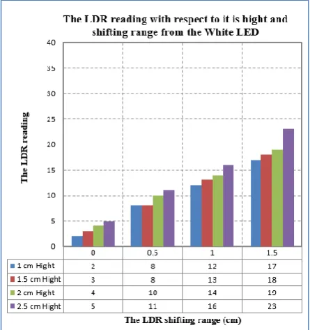
Fig. 11, 12, 13 and 14 show that the White color LED has a good performance for all distances when compare with the other color LEDS because it produces a good sensing range reading for the LDR sensor, so that this color LED is a more suitable color to be used in the localization system. Fig. 15 shows The LDR reading from the White color LED for different high and different shifting range.
Fig .15. Illustration the LDR reading from the White color LEDs for different high and shifting range.
3.2 IR Experiments
These experiments are used to test the sensing range of the IR pair with different high and different shifting range between the IR transmitter and IR receiver. The same distances for high and shifting range in last experiment are used in this experiments. In these experiments both the IR transmitter and the IR receiver are connected to an aduino UNO which connected to laptop through USB cable as shown in Fig. 16. Fig.17 shows the schematic diagram for these experiments.
Fig .9. The experiments for testing the sensing range of the IR receiver from the IR transmitter for different high
[image:5.595.339.521.470.725.2]Fig .17. The schematic diagram for the experiments of the IR transmitter and receiver.
[image:6.595.54.282.405.641.2]The experiment result is obtained by changing the shifting range between the IR receiver and transmitter sensor (0, 0.5, 1 and 1.5 cm) with different altitude range between the IR transmitter and receiver (1.5, 2 and 2.5 cm) as shown in Fig. 18.
Fig .18. Illustration the IR receiver reading from the IR transmitter for different high and shifting range.
3.3 RFID Experiments
These experiments are used to test the sensing range of the different high and different shifting range between the RFID readers with the RFID Tags. The experiment board has two types of square Tags board with 19 cm for each side: The red board is used for fixing a grid contains 5*5 RFID Tags and the blue board is used for fixing 3*3 RFID Tags. These types
are used to produce different shifting range between the RFID reader and the RFID Tags. The same distances for high and shifting range in last experiment are used in this experiments. In these experiments both the RFID reader and the RFID Tags are connected to an aduino UNO which connected to laptop through USB cable as shown in Fig. 19. Fig.20 shows the schematic diagram for these experiments.
Fig .20. Illustration of the RFID Reader schematic diagram.
The experiment result is obtained by changing the shifting range between the IR receiver and transmitter sensor (0, 0.5, 1 and 1.5 cm) with different altitude range between the IR transmitter and receiver (1.5, 2 and 2.5 cm) as shown in Fig. 18.
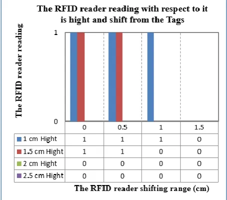
Fig .21. Illustration the RFID reader reading from the RFID Tags for different high and shifting range.
4.
CONCLUSION
This paper has focused on the ability of choosing a suitable sensor for implementation a localization system. The chosen sensors are distributed as a matrix of sensors to work as a localization points for any robot placed on the environment. The experiments have tested the low cost LEDs & LDR, IR transmitter & receiver and RFID Tag & Reader which are able to obvious reliable range to demonstrate the measurements. The experiment results show that the RFID reader and Tags produce a more accurate measurements than other sensors and it is non-effected by neither color nor light. The drawback of this sensor is the interference occurs when more than one Tag
are within the sensing range of the RFID reader. Other drawbacks are it has more cost than the other sensors and also has the bigger size which leads to increase the distance among these sensors when distributed in the environment. The increasing of the distance means reducing the accuracy of localization system.
The IR transmitter and receiver can be used to produce a more accurate result like the RFID system by making a distinct code for each IR transmitter but this process leads to make the system more complex. The small size of this sensor give us the ability of decrease the distance among these sensors when distributed in the environment. The drawback of this sensor that it is reading effects by the infrared radiation of the sun light.
The LED and LDR sensors are the low cost than the other sensors and have the same size of the IR sensors. So that can be consider as a low cost system when compare with the other sensors but on the other hand these sensors required a more complex software for building a localization system and also the sun and lamp light are more effect on these sensors than the IR and the RFID sensors.
5.
REFERENCES
[1] O. A. Hasan, A. T. Rashid, R. S. Ali and J. Kosha,” A Practical Performance Analysis of Low-Cost Sensors for Indoor Localization of Multi-Node Systems “, Internet Technologies and Applications (ITA), Wrexham UK, September 2017.
[2] O. A. Hasan, A. T. Rashid and R. S. Ali,” Centralized approach for multi-node localization and identification “, Iraq J. Electrical and Electronic Engineering, Vol.12 No. 2, pp. 178-187, 20 1 6.
[3] O. A. Hasan, A. T. Rashid and R. S. Ali,” A Hybrid approach for multi-node localization and Identification “,
Basrah Journal for Engineering Sciences, vol. 16, no. 2, pp. 11- 20, 2016.
[image:7.595.54.282.375.575.2]the 2008 IEEE International Conference on Robotics and Biomimetics Bangkok, Thailand, PP. 21 - 26, 2009.
[5] H. Chae and K. Han,” Combination of RFID and Vision for Mobile Robot Localization “International Conference on Intelligent Sensors, Sensor Networks and Information Processing, Australia, 2005.
[6] A. T. Rashid, M. Frasca, A, A, Ali, A. Rizzo and L. Foruna,” Multi-robot localization and orientation estimation using robotic cluster matching algorithm. Robotics and Autonomous Systems, Vol. 63, p.p. 108– 121, 2015.
[7] A. T. Rashid, W. H. Zayer and M. T. Rashid,” Design and Implementation of Locations Matching Algorithm for Multi-Object Recognition and Localization”, Iraqi Journal of Electrical and Electronic Engineering, Vol. 14, No. 1, p.p. 10-21, 2018.
[8] Y. T. Win, H. T. Htun, N. Afzulpurkar and C. Punyasai ,” Ultrasonic System Approach to Obstacle Detection and Edge Detection”, Sensors & Transducers Journal, Vol. 127, Issue 4, pp. 56-68, 2011.
[9] B. Mustapha, A. Zayegh1and R.K. Begg,” Microcontroller BasedWireless Obstacle Detection System for the Elderly”, 2014 4th International Conference on Artificial Intelligence with Applications in Engineering and Technology, 2014.
[10] M. R. Yaacob, N. S. N. Anwar, and A. M. Kassim, “Effect of glittering and reflective objects of different colors to the output voltage-distance characteristics of sharp GP2D120 IR,” ACEEE Int. J. on Electrical and Power Engineering, vol. 03, no. 02, 2012.
[11] M. Sugano, T. Kawazoe, Y. Ohta, and M. Murata,” Indoor Localization System Using RSSI Measurement
Of Wireless Sensor Network Based On ZIGBEE Standard”, 6th, IASTED International Multi-conference on Wireless and Optical Communications, 2006.
[12] A. Howard, M. J Mataric, and G. S Sukhatme,” Mobile Sensor Network Deployment using Potential Fields: A Distributed, Scalable Solution to the Area Coverage Problem”, H. Asama et al. (eds.), Distributed Autonomous Robotic Systems 5 © Springer-Verlag Tokyo 2002.
[13] S. N. Kumar,” Energy – Saving Smart Street Light Intensity Control System using Arduino”,IJCST Vol. 8, ISSue 1, 2017.
[14] T. P. Huynh1, Y. K. Tan and K. J. Tseng,” Energy-Aware Wireless Sensor Network with Ambient Intelligence for Smart LED Lighting System Control “, 37th Annual Conference of the IEEE Industrial Electronics Society, 2011.
[15] A. Kumar, H. Sinha, U. Rehman and P.D.Yadav,” Low Cost Line Follower Obstacle Detector and DTMF Tone Robot”, International Journal of Scientific and Research Publications, Volume 6, Issue 6, June 2016.
[16] H. T. Abbas, H. H. Abdullah, M. A. Mohanna , H. A. Mansour and G. S. Shehata1,” High RCS Compact Orientation independent Chipless RFID Tags Based on Slot Ring Resonators (SRR) “,2018, 35th NATIONAL RADIO SCIENCE CONFERENCE (NRSC 2018), March 20 - 22, 2018.