© 2019, IRJET | Impact Factor value: 7.211 | ISO 9001:2008 Certified Journal
| Page 2289
Pranav K Chandran
1, Aasha
21
PG Student, Department of Civil Engineering, ECET, Coimbatore, India
2Assistant
Professor, Dept. of Civil Engineering, ECET, Coimbatore, India
---***---Abstract -
Reinforced concrete beams needs to bestrengthened when the existing steel reinforcement in the beams are insufficient or subjected to corrosion or unsafe. Thus the need for rehabilitation and up gradation of existing structure has drawn an urgent demand to find a rapid and cost-effective repair technology. This paper summarizes an experimental investigation on Reinforced Concrete beams strengthened by wrapping with Glass Fibre Reinforced Polymer (GFRP) sheets and treating with Polymer Cement Mortar (PCM) on the bottom tensile portion. The GFRP wrapped beams were tested after 24 hours. The beams treated with polymer cement mortar were subjected to loading i) after 24 hours and ii) 7 days air curing. The results were then compared with control beams. A total of 12 beam specimens were casted which were designed to be weak in flexure. The beams were tested in a static two point loading test setup. The test results were evaluated in terms of load deflection behavior, ultimate load carrying capacity, ultimate deflection, crack patterns and associated failure modes
Key Words
:
GFRP, PCM, SBR Latex, RC Beam, Two Point Loading
1.INTRODUCTION
Concrete is the most widely-used construction material in the world of civil infrastructure over several decades. Reinforced-concrete (RC) structures are subjected to deterioration during their service life. Thus rehabilitation works are often required to restore the performance of these deteriorated structures. There are several materials that have been introduced in the construction industry for repairs of deteriorated structures. Among them, the most commonly used materials are polymer cement mortar (PCM), fiber-reinforced polymer (FRP) and ultra-high-strength fiber-reinforced concrete (UFC) panels. Fibre-reinforced plastic (FRP) is a composite material made of a polymer matrix reinforced with fibres. The use of FRP composite materials with various types of fibre reinforcements has become an alternative for reinforcement in various concrete members. Carbon Fibre Reinforced Polymer (CFRP) is the best type of FRP strengthening. But because of its high cost, its use is being limited. Thus, this makes Glass Fibre Reinforced Polymer (GFRP), the most commonly used type of FRP strengthening technique. Polymer Cement Mortar (PCM) is a cementitious material having better adhesive strength and resistance to aggressive environments compared to ordinary mortar and concrete.
PCM overlays are generally used to strengthen structural elements such as bridges, slabs, beams and columns. They are being used as the promising repair material for Reinforced Concrete. As a result of polymerization, the PCM exhibits excellent bonding with parent concrete, less shrinkage, less water absorption, chloride penetration, carbonation and other superior durability properties compared to ordinary cement mortar.
2. SCOPE
In this thesis, the effect of GFRP sheets and PCM on the bottom tensile portion of RC beam is studied. 12 beam specimens, that are designed to be weak in tension were casted. The beams wrapped with GFRP were subjected to loading after 24 hours. The beams with PCM were tested after 24 hours and 7 days of curing. A comparison of result is made with control beams. Static two point loading is carried out in order to determine the load deflection, ultimate load carrying capacity, ultimate deflection, crack patterns and associated failure modes.
3. EXPERIMENTAL INVESTIGATION
In order to determine the effect of strengthening of Reinforced Concrete beams using GFRP and PCM, normal RC beams with GFRP and PCM on the bottom tensile portion were casted and tested
3.1
Preparation of specimen
The required quantities of cement, fine aggregate, coarse aggregate and water was taken for the specimens. Initially cement, fine aggregate and coarse aggregate was hand mixed in dry state for about 2 minutes. The measured quantity of water was added stage by stage. M25 mix is used.
3.2
Casting of specimens
© 2019, IRJET | Impact Factor value: 7.211 | ISO 9001:2008 Certified Journal
| Page 2290
Fig -1: Specimen after casting
3.3
Strengthening of specimens
After the curing period of 28 days,
i. A set of beams were wrapped with 8 layers of GFRP (0.3 mm thick) throughout the bottom portion and was subjected to 24 hours air curing
ii. A set of beams were treated with Polymer Cement Mortar overlay at a thickness of 25 mm throughout the tensile portion and was subjected to 24 hours air curing
iii. A set of beams were treated with Polymer Cement Mortar overlay at a thickness of 25 mm throughout the tensile portion and was subjected to air curing for 7 days
3.3 Test Rig and
Instrumentation
Beams after strengthening were subjected to flexural strength test. The test setup consists of a 30 T loading frame. The deflection of the beam was determined by attaching a dial gauge at the bottom centre of the beam. For testing of the beam specimens, the supports were provided at a distance of 130 mm from the edge of the beam. In case of a beam of span 1250 mm, the effective span is taken as 990 mm. A proving ring of 500 kN is attached at the top of the beam to determine the applied load. The test setup for loading specimens is shown in Fig 3.
The flexural strength of beam is tested with a two point loading system with the help of a hydraulic jack attached to the loading frame. The behavior of beam from beginning to the failure was observed carefully. The loading of the beam was terminated just on the verge of collapse. The development and propagation of first crack was observed keenly. The values of applied loads and the corresponding deflections were noted and the load-deflection curve is plotted which is taken as the output. The load is applied uniformly perpendicular to the beam and is incremented up to the breaking point or failure of the material.
Fig -2: Specimen after casting
4. RESULTS AND DISCUSSIONS
4.1 Load Deflection Behavior
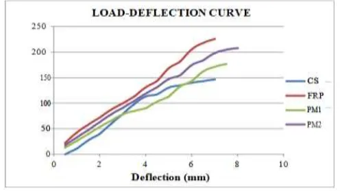
All the specimens show a straight line relationship between applied load and corresponding deflection up to cracking load. The deflections are found to increase rapidly with considerable deviation from linearity after cracking until failure of the beam. The load vs deflection curves for control beam, GFRP strengthened beams and beams externally treated with polymer cement mortar are given in Chart 1. It can be observed that the strengthened beams are stiffer compared to control beams. The curves for all the strengthened beams showed similar response in the initial stage of loading till the formation of first crack. But with the increase in load, a variation was observed for PM1
Chart -1: Load Deflection Curve
4.2 Load carrying capacity
[image:2.595.302.559.60.249.2] [image:2.595.310.558.470.609.2]© 2019, IRJET | Impact Factor value: 7.211 | ISO 9001:2008 Certified Journal
| Page 2291
carrying capacity of the specimens are listed in Table 1.Chart -2: Initial crack load and failure load of specimens
. Table - 1: Ultimate load capacity of specimens Beam Specimen Ultimate Load (kN)
CS 146.63
FRP 225.67
PM1 176.68
PM2 207.98
The ultimate load carrying capacities of strengthened specimens are higher than that of control specimen. The GFRP strengthened beam shows maximum load carrying capacity compared to PCM overlaid beams. For beams strengthened with GFRP, the percentage increase in ultimate load depends on the number of layers of GFRP and the thickness of layers of GFRP wrapping. The graph showing the percentage increase in ultimate load for strengthened specimens (FRP, PM1, PM2) with respect to the control specimen is shown in Chart 3.
Chart -3: % Increase in Ultimate Load of Specimens
were noted. It was observed that the ultimate deflections for CS and FRP specimens were the same; while that for PM1 the value was observed to be 7.5 mm. PM2 showed the highest central point deflection of 8 mm compared to other specimens. The ultimate deflection of the specimen is shown in Chart 4.
Chart -4: Ultimate deflections of specimen
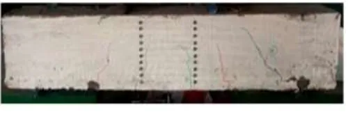
4.4 Crack patterns
In PM1 and PM2 specimens, formation of cracks has been reduced i.e., the number of cracks has been lesser than FRP and CS specimens. Thus it can be concluded that Polymer Cement Mortar overlay helps in reducing the number of cracks. It was also observed that the spacing between cracks was also more. The crack spacing was more in PM2 when compared to PM1. The propagation of cracks was restricted in case of FRP specimen. The graph showing the cracking loads of beams are shown in Chart 5. Crack patterns in beam specimens (CS, FRP, PM1, and PM2) are shown in Fig 3 to Fig 6 respectively.
© 2019, IRJET | Impact Factor value: 7.211 | ISO 9001:2008 Certified Journal
| Page 2292
Fig -3: Specimen after casting
Fig -4: Specimen after casting
Fig -5: Specimen after casting
Fig -6: Specimen after casting
4.4 Failure modes
All the specimens were designed for flexural failure. The CS and FRP specimen failed through pure flexural failure by the development of flexural cracks. Rupture of GFRP laminates at bottom of beam or crushing of concrete at top of beam was not observed till failure. On the other hand, the beams which were strengthened using polymer cement mortar overlay showed debonding failure. The interface between concrete and PCM debonded off at the supports. extend of debonding reduces with the increase in curing period. The debonding failures in PM1 and PM2 specimens are shown in Fig 7 and Fig 8 respectively.
Fig -7: Specimen after casting
Fig -8: Specimen after casting
5. CONCLUSIONS
i. Strengthening of beams provide additional stiffness to the beams. The reduced deflection in FRP specimens indicates an increase in stiffness.
ii. All the specimens showed a linear relationship between load and deflection until the formation of cracks
iii. The strengthened beams, in all cases, took more loads than the control beams. The load taken by beams subjected to GFRP strengthening technique was greater than PCM treated beams iv. Compared with the control specimen, the beams wrapped with 8 layers of GFRP sheets showed about 53% increase in load carrying capacity. The load carrying capacity can be further increased by increasing the number of layers of GFRP wrapping
v. The compressive strength of polymer cement mortar cubes was higher than that of ordinary cement mortar cubes (by about 3% for water cured cubes and 5% for dry cured cubes. vi. Compressive strength of PCM cubes subjected
[image:4.595.38.548.38.687.2] [image:4.595.38.288.442.524.2]© 2019, IRJET | Impact Factor value: 7.211 | ISO 9001:2008 Certified Journal
| Page 2293
viii. PCM limits the formation of cracks and itswidening. The spacing between cracks also increases with the increase in curing period.
ix. GFRP helps to limit the propagation of cracks and
its widening.
x. The deflections of FRP specimens were much lesser than that of PCM specimens.
xi. Beams strengthened with GFRP wrappings showed perfect bonding between GFRP sheets and concrete for entire range of loading. No debonding of GFRP or crushing of concrete was observed.
xii. Beams strengthened with PCM layer showed
debonding failure between the concrete and
polymer cement mortar layer at the supports
.
REFERENCES
[1] Dawel Zhang, Khuram Rashid, Bo Wang and Tamon
Ueda (2017)
, “
Experimental and Analytical Investigation of Crack Spacing and Width for Overlaid RC Beams at Elevated Temperature,” J. Struct. Eng., 143(12), 10.1061/(ASCE)ST.1943-541X.0001910.[2] Dawei Zhang, Tamon Ueda and Hitoshi Furuuchi
(2013), “Fracture Mechanisms of Polymer Cement Mortar: Concrete Interfaces”, Journal of Engineering Mechanics © ASCE, pp. 167-176.
[3] Hota V. S. Gangarao and P. V. Vijay (1998), “Bending
Behavior of Concrete Beams Wrapped with Carbon Fabric”, J. Struct. Eng., 124(1), 3-10.
[4] Jais John and Sachin Paul (2015), “Study of Properties of
Polymer Modified Mortars used as Repair Materials”, International Journal of Science Technology and Engineering, 2(5), 52-57
[5] Khashayar Jafari (2017), “Experimental and Analytical
Evaluation of Rubberized Polymer Concrete”, J. Construct. and Building Mater., 14(4), 631-642.
[6] L. K. Aggarwal, P. C. Thapliyal and S. R. Karade (2007),
“Properties of polymer-modified mortars using epoxy and acrylic emulsions”, J. Construction and Building Materials , Vol. 21, pp. 379–383.
[7] Pradeep Singh, Abhishek Mishra and Arpit Kulshreshtha
(2016), “Finite Element Analysis Of Reinforced Concrete Beam Using Ansys”, International Journal of Current Engineering and Scientific Research, 3(1),122-126.
[8] Siddharth and Koushik Paul (2016), “Strengthening of
an RC Beam using Synthetic FRP Laminates”, Indian Journal of Science and Technology, 9(41), 1-5.
[9] S. Tejaswi and J. Eeshwar Ram (2015), “Flexural