1
Crosstalk Aware Multi-Bit Error Detection with Limited
Error Correction Coding for Reliable On-Chip
Communication
Wameedh Nazar Flayyih
PhD, Department of Computer Engineering,
University of Baghdad, Baghdad, Iraq
ABSTRACT
Reliability of on-chip communication became a challenge in deep submicrometer (DSM) region due to the increased effect of the different noise sources and the crosstalk between adjacent interconnects. This led to the introduction of many coding schemes to jointly address both issues. In this paper, high error detection with single error correction joint coding scheme is proposed. The proposed scheme limits its error correction to single error as it was found that this meets the performance requirements while allowing the scheme to detect higher number of errors, namely six errors in this proposed scheme. The proposed scheme was implemented in two different designs, one optimized for higher performance and the other for smaller area. The two designs were evaluated and compared to similar coding schemes. The scheme achieved higher reliability and maintained high throughput. As compared to previous work, the first implementation achieved 4% higher frequency whereas the second implementation achieved 13% smaller area and 11% lower power.
General Terms
VLSI, Network on Chip.
Keywords
Error control, fault tolerance, network on chip
1.
INTRODUCTION
Network on chip (NoC) was introduced as a solution for the increasing on chip communication between the many components in a single chip [1,2]. This became important as traditional buses do not meet the performance and energy requirements of the increased number of integrated blocks [3,4].
As semiconductor technology continues to scale down, different noise sources affect the on chip communication infrastructure which results in transient faults leading to unreliable data transmission. Power supply noise, alpha particle hits, electromagnetic interference (EMI), and transistor variability [5,6] represent some sources of transient faults. In addition to these sources, crosstalk between adjacent wires became one of the major concerns due to its negative effect on signal integrity and the imposed timing delays. The root cause of crosstalk is the continuously decreasing wire spacing and increasing wire aspect ratio which increases the coupling capacitance [5-7].
To jointly address the reliability issues imposed by the transient faults and simultaneously address crosstalk timing effects, different joint codes were proposed. Early schemes achieved single error correction with crosstalk reduction like duplicate-add-parity (DAP) [8], dual rail [9], boundary shift
code [10], and modified dual rail code [11]. More powerful joint codes were later proposed like the joint crosstalk avoidance and triple error correction (JTEC) scheme and the JTEC with simultaneous quadruple error detection (JTEC-SQED) scheme [12]. The latter was enhanced in [13] to provide lower power consumption at lower noise levels. The authors in [14] proposed a new joint scheme providing seven errors detection at the cost of no error correction. The absence of error correction negatively affects performance due to the high number of retransmissions at high bit error rates. On the other hand, providing three errors correction as in JTEC-SQED is considered a waste in the redundancy available. This paper argues that it is possible to modify JTEC-SQED to provide higher detection while limiting its correction capability to single errors. Although it is theoretically possible to provide seven errors detection using the same redundancy, this may lead to high retransmission rate as in [14] due to the absence of error correction. In addition, the adaptivity provided in [13] can also be applied to the new proposed scheme.
The rest of this paper is organized as follows. Section 2 compares the performance effect of different correction capabilities by analyzing the retransmission effect on throughput. Section 3 introduces the proposed coding scheme. Section 4 evaluates the scheme as compared to JTEC-SQED from reliability, frequency, and area perspectives. Section 5 concludes the paper.
2.
RETRANSMISSSION PROBABILITY
It is known that to simultaneously correct tc-errors and detect td-errors, the minimum Hamming distance D should be tc+td+1, where td ≥ tc [15]. Since duplication of Hamming single error correction double error detection (SECDED) codeword, as in JTEC-SQED scheme, achieves D=8 [12], then it can theoretically be designed as one of the schemes in Table 1.
Table 1. Possible schemes with Hamming distance =8. Scheme tc td
7ED 0 7
1EC6ED 1 6
2EC5ED 2 5
When the decoder detects uncorrectable error(s), a retransmission request is sent to the encoder. The encoder re-encodes the original data stored in the retransmission buffer and sends the codeword again.
Assuming a coding scheme can correct up to tc errors and can detect up to td errors, then the retransmission probability Pret
can be given by summing the probabilities of errors that can be detected but not corrected:
𝑃
𝑟𝑒𝑡=
𝑃
𝑖−𝑒𝑟𝑟𝑜𝑟𝑠 𝑡𝑑𝑖=𝑡𝑐 +1
(1)
where Pi-errors represents the probability to have i errors in the
L bits word, and is given by [5,15]:
𝑃
𝑖−𝑒𝑟𝑟𝑜𝑟𝜀 =
𝐿
𝑖
𝜀
𝑖
1 − 𝜀
𝐿−𝑖 (2)where
𝐿
𝑖
=
𝐿!
𝑖! 𝐿 − 𝑖 !
(3)For small ε, the probability of tc+1 errors dominates, and Pret
can be approximated by:
𝑃
𝑟𝑒𝑡=
𝐿
𝑡𝑐 + 1
𝜀
𝑡𝑐 +1 (4)
As a result, the retransmission probability depends on the error correction capability.
NoC designs usually adopt the Go-Back-N retransmission policy instead of selective repeat [16,17]. In this policy, the sender can transmit N flits (flow control units in NoC) without receiving acknowledgement. The round trip time between two neighbor NoC routers can be predetermined at design time. It includes the flit encoding, flit transfer over the link, flit decoding, and acknowledgment transfer back over the link. So, the window size (N), is usually the round trip time. As a result, when a retransmission request is received by the sender it should retransmit N flits, starting with the requested flit. Since any flit may be retransmitted one or more times, then it is required to find the average number of flit transmissions required to be successfully accepted by the decoder, T. This average number includes the probability to be accepted in the first transmission, or after one or more retransmissions, as given by [14,15]:
𝑇 = 1 +
𝑁𝑃
𝑟𝑒𝑡1 − 𝑃
𝑟𝑒𝑡(5)
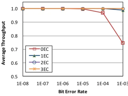
[image:2.595.325.531.78.233.2]The average codec throughput is the reciprocal of T above. Fig. 1 shows how the average throughput of the different schemes in Table 1 is affected by the increased bit error rate, assuming round trip time N=4. It is obvious that the automatic repeat request (ARQ) scheme (seven error detection without correction capability, 0EC) suffers from throughput degradation at high bit error rates reaching 25.3% reduction. On the other hand, single error correction scheme preserves throughput with a maximum degradation of 1.2%. From this, it is clear that SEC6ED achieves the highest detection while preserving performance. Accordingly, JTEC-SQED will be redesigned to achieve SEC6ED.
Fig. 1 Average throughput as a function of bit error rate for different correction schemes
3.
PROPOSED SINGLE ERROR
CORRECTION SIX ERROR
DETECTION SCHEME
3.1
Encoding
[image:2.595.330.529.444.583.2]The encoding part shown in Fig. 2 is the same as that of JTEC-SQED and is composed of two main stages. The first is the encoding using SECDED coding and the resultant codeword is then passed to the second stage which is duplication of all the data and check bits giving the codeword shown in Fig. 3. In addition, the encoder includes a retransmission buffer since the coding is Hybrid ARQ (HARQ), meaning it has retransmissions. In addition to duplication, the two copies are interleaved to provide crosstalk reduction.
Fig. 2 Encoding part
The encoder implements the Hsiao code instead of Hamming as SECDED code to reduce the chain of XOR gates to calculate the overall parity [12]. Hsiao code works as SEC code by dropping any one of the (h + 1) parity bits [12]. It should be noted that in Hsiao coding the resultant syndrome is zero when there are no errors, and it has even and odd number of 1s when there are even and odd number of errors, respectively. Also, for SECDED codes, four or six errors may result into another valid codeword which results into zero syndrome.
0.5 0.6 0.7 0.8 0.9 1.0
1E-08 1E-07 1E-06 1E-05 1E-04 1E-03
A
ve
ra
ge
T
hr
ou
ghp
ut
Bit Error Rate
0EC 1EC 2EC 3EC
Buffer
H
S
IA
O
S
E
C
D
E
D
e
n
c
o
d
e
r
Flit k k
k
k
k+h+1
k+h+1 k+h+1
duplication
retransmit A
3
Fig. 3 Codeword output from the encoder
3.2
Decoding
The proposed decoding algorithm is based on the syndromes of the two copies A and B along with the number of 1s in each syndrome. In addition, it makes use of comparing the two copies and correcting single errors in each.
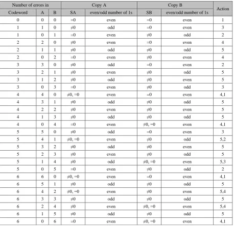
In order to prove the capability of duplicated Hsiao SECDED to detect six errors and correct single error we should check all the cases from error free case up to 6 errors. In order to be successful, the decoding scheme should be able to differentiate between the cases which will not require retransmission (error free case and single error cases) in one hand and all the other cases that will require retransmission (two up to six error cases). All the error patterns and their corresponding syndromes are listed in Table 2 and the actions taken can be grouped into five:
1. The error free case results into syndrome A (SA) and syndrome B (SB) to be zero, but this may also be the case when four or six errors affect one of the copies converting it to a valid codeword making the syndrome zero. If the two copies match then it is the error free case, D0
D0
D1
D1
Dk-1
Dk-1
P0
P0
Ph-1
Ph-1
C
o
p
y
A
H
+
1
b
it
s
C
o
p
y
B
H
+
1
b
it
s
Ph
D
a
ta
b
it
s
k
b
it
s
S
E
C
D
E
D
C
h
e
c
k
b
it
s
h
+
1
b
it
s
D
a
ta
b
it
s
k
b
it
s
S
E
C
D
E
D
C
h
e
c
k
b
it
s
h
+
1
b
it
s
Ph
Table 2 Error patterns and the corresponding syndromes and actions
Number of errors in Copy A Copy B
Action Codeword A B SA even/odd number of 1s SB even/odd number of 1s
0 0 0 =0 even =0 even 1
1 1 0 ≠0 odd =0 even 3
1 0 1 =0 even ≠0 odd 2
2 2 0 ≠0 even =0 even 4
2 1 1 ≠0 odd ≠0 odd 5
2 0 2 =0 even ≠0 even 4
3 3 0 ≠0 odd =0 even 2
3 2 1 ≠0 even ≠0 odd 5
3 1 2 ≠0 odd ≠0 even 5
3 0 3 =0 even ≠0 odd 3
4 4 0 ≠0, =0 even =0 even 4,1
4 3 1 ≠0 odd ≠0 odd 5
4 2 2 ≠0 even ≠0 even 5
4 1 3 ≠0 odd ≠0 odd 5
4 0 4 =0 even ≠0, =0 even 4,1
5 5 0 ≠0 odd =0 even 3
5 4 1 ≠0, =0 even ≠0 odd 5,2
5 3 2 ≠0 odd ≠0 even 5
5 2 3 ≠0 even ≠0 odd 5
5 1 4 ≠0 odd ≠0, =0 even 5,3
5 0 5 =0 even ≠0 odd 2
6 6 0 ≠0, =0 even =0 even 4,1
6 5 1 ≠0 odd ≠0 odd 5
6 4 2 ≠0, =0 even ≠0 even 5,4
6 3 3 ≠0 odd ≠0 odd 5
6 2 4 ≠0 even ≠0, =0 even 5,4
6 1 5 ≠0 odd ≠0 odd 5
[image:3.595.70.529.326.770.2]otherwise a retransmission is requested.
2. A single error affecting copy B leads to SA=0 and SB≠0 with odd number of ones. This is also the case if three or five errors affect copy B. It may also occur when single error affects B and four errors affect A converting it to a valid codeword making SA=0. A single error can be corrected using SB, so if the corrected copy B match copy A then it is a single error, otherwise it means it is three or five errors and a retransmission is requested. 3. Similar to point 2 above applies to single error affecting
copy A leading to SA≠0 with odd number of ones and SB=0.
4. If any syndrome is nonzero with even number of ones, then it means it has even number of errors (i.e. ≥2) which
mandates retransmission.
5. If both syndromes are nonzero, regardless of the number of ones, then each copy has at least one error. So the whole codeword has two or more errors, which requires retransmission.
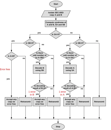
[image:4.595.93.523.244.747.2]Fig. 4 shows the decoding algorithm flowchart based on Table 2 and the corresponding actions.
Fig. 4 Proposed decoding algorithm flowchart
Is SA=0?
Is SB=0? yes
yes
no
Is there odd number of
1s in SB?
Decode B using SB
yes
Retransmit
no
yes yes
Isolate SEC-DED copy A and B
Compute syndrome of A and B, SA and SB
Start
Stop Is A=B?
Accept any copy as error free
no
Is decoding result of B=A?
Accept any copy as error free
Retransmit no
Is SB=0?
no
Is there odd number of
1s in SA?
Decode A using SA
yes
yes Is decoding result of A=B?
Accept any copy as error free
yes
Retransmit no
no
Retransmit no
Error free
1 error in B
5
3.3
Decoder Hardware
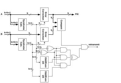
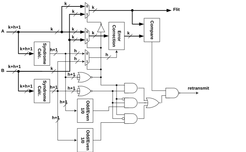
The decoding algorithm was realized in two different implementations. The first implementation shown in Fig. 5 is inherited from the JTEC-SQED decoding. It has two syndrome calculation units and two error correction units, one for each copy. The error correction is done based on the syndrome and can correct single error, and when a zero syndrome is passed to this unit the input is passed to the output unchanged. The retransmission decision is taken according to the algorithm in Fig. 4 based on the values of both syndromes and the result of comparison between the outputs of the correctors.
It can be observed from Fig. 4 that for any case there is no need to pass the two copies through the corrector.
- In action 1, where both syndromes are zero, there is no need for passing any copy through the corrector. Also, it should be noticed that even if any copy passes through the corrector no change will take place since the syndrome is zero.
- In action 2, where SA=0 and SB≠0, copy B should be corrected while copy A should be left unchanged. - In action 3, where SA≠0 and SB=0, copy A should be
corrected while copy B should be left unchanged. - In actions 4 and 5, none of the copies is required to be
corrected.
According to this, the second decoder implementation shown in Fig. 6 uses one corrector unit which takes the copy that has a nonzero syndrome. The compare unit compares the output of the corrector with the copy that was not passed to the corrector. This implementation omits one correction unit which achieves area savings that is limited by the extra multiplexors. An expected penalty is the increase in the critical path delay due to the multiplexors at the input of the correction unit.
4.
EVALUATION
In this section, the proposed scheme in both implementations is compared to JTEC-SQED. The evaluation includes the reliability achieved represented by the undetected error probability, the maximum encoder and decoder frequency, the consumed area, and the power consumption.
4.1
Undetected Error Probability
The reliability provided by any coding scheme can be evaluated through the probability of decoding failure (undetected error probability), which is the probability that a codeword with one or more errors pass undetected by the decoder [15].
For a bit error rate ε, an L bits word is received error free when none of the bits has error which has a probability of (1-ε)L
. The probability that the codeword has one or more errors is (1-(1-ε)L). The latter represents the uncoded case failure probability since any error will be undetected. On the other hand, the words encoded with an error protection scheme will have different undetected error probability (Pund) according to
the scheme detection capability.
For the proposed SEC6ED scheme it is known that it can detect up to six errors but fails when seven errors occur. Since not all seven errors cause a failure to the scheme, all the possible seven error patterns are shown in Table 3. Although not all cases in patterns 4 and 5 lead to failure, the model will be considered as an upper bound. Accordingly, the undetected error probability model for the proposed scheme is:
𝑃
𝑢𝑛𝑑 −1𝐸𝐶6𝐸𝐷= 2
𝐻 + 1
4
𝐻 + 1
3
𝜀
7 (6)
The Pund of JTEC and JTEC-SQED are given in [18] as
follows:
𝑃
𝑢𝑛𝑑 −𝐽𝑇𝐸𝐶=
5𝐻
2
𝐻 + 1
3
𝜀
[image:5.595.132.532.475.750.2]4 (7)
Fig. 5 First implementation of the proposed decoder
S
y
n
d
ro
m
e
C
a
lc
.
E
rr
o
r
C
o
rr
e
c
tio
n
A
k k
S
y
n
d
ro
m
e
C
a
lc
.
E
rr
o
r
C
o
rr
e
c
tio
n
B k
k
C
o
m
p
a
re
k
retransmit k+h+1
h+1
h+1
h+1
h+1
h+1 h+1
h
h
O
d
d
/E
v
e
n
1
/0
O
d
d
/E
v
e
n
1
/0
Flit
k+h+1 k+h+1
𝑃
𝑢𝑛𝑑 −𝐽𝑇𝐸𝐶 −𝑆𝑄𝐸𝐷= 2
𝐻 + 1
3
𝐻 + 1
2
𝜀
5 (8)
The undetected error probability as a function of increased bit error rate is shown in Fig. 7. As expected, the reliability increases (represented by reduced Pund) as the error detection
capability increases. For instance, at ε =10-4
the proposed 1EC6ED achieves Pund =2×10-19, whereas the JTEC and
JTEC-SQED achieve Pund =9×10
-11
and Pund =2×10
-13
respectively, as shown by the vertical line in the figure. From another perspective represented by the horizontal line, it can be seen that to achieve a specific target Pund, the 1EC6ED can
sustain higher BER than both JTEC and JTEC-SQED which make it more suitable for higher noise environments.
4.2
Area, Maximum Frequency, and Power
Consumption
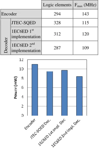
[image:6.595.125.529.76.325.2]The two proposed hardware implementations and the JTEC-SQED scheme were implemented in Verilog HDL, verified in ModelSIM, and evaluated on an FPGA Cyclone IV GX EP4CGX150DF31I7AD device. The encoder is the same for all the schemes under consideration so it is reported once in Table 4 and Fig. 8. For all the schemes the decoders are slower than the encoder, and in pipelined operation the slowest stage governs the frequency. The first decoder implementation has 4% higher maximum frequency than
[image:6.595.70.529.361.595.2]Fig. 6 Second implementation of the proposed decoder
Table 3 1EC6ED Decoding of Patterns of 7 Errors and Respective Number of Combinations Pattern
No.
No. of
Errors Syndrome=0?
No. of 1s in
Syndrome Decoder Action Decoding
Correctness No. of combinations
A B A B A B
1 7 0 N Y odd even Retransmit Correct
2 6 1 Y or N N even Odd Retransmit /
Retransmit Correct / Correct
3 5 2 N N odd Even Retransmit Correct
4 4 3 Y or N N even Odd May select copy A/ Retransmit
Incorrect / Correct 5 3 4 N Y or N odd Even May select copy
B/ Retransmit
Incorrect / Correct
6 2 5 N N even Odd Retransmit Correct
7 1 6 N Y or N odd even Retransmit /
Retransmit Correct / Correct
8 0 7 Y N even odd Retransmit Correct
*Y: Yes N: No
S
y
n
d
ro
m
e
C
a
lc
.
E
rr
o
r
C
o
rr
e
c
tio
n
A k
S
y
n
d
ro
m
e
C
a
lc
.
B k
O
d
d
/E
v
e
n
1
/0
O
d
d
/E
v
e
n
1
/0
C
o
m
p
a
re
retransmit h+1
h+1
h+1 h+1
h
h+1 k
h h
k k
k
k
h+1 0
1 0
1 0
1
Flit
k
k k+h+1
k+h+1
k+h+1
7 JTEC-SQED decoder whereas the second implementation is
5% slower than JTEC-SQED. The reduced frequency of the second implementation is due to the increased critical path delay introduced by the multiplexors at the input of the correction unit.
The first implementation of 1EC6ED decoder consumes 5% less area than JTEC-SQED. On the other hand, the second implementation consumes 13% less area than JTEC-SQED. The higher area savings achieved by the second implementation is a result of omitting one correction unit. Both implementations have less area than JTEC-SQED due to their simpler decision logic.
The dynamic power consumption is estimated using PowerPlay Power Analyzer in Quartus II tool at 100 MHz operating frequency. The power consumption of the encoder is higher than that of all the decoders. The main contributor to this high power consumption is the large number of registers due to the retransmission buffer. The first decoder implementation of 1EC6ED consumes 3% higher power than JTEC-SQED whereas the second implementation consumes 11% and 14% less power than JTEC-SQED and the first implementation, respectively.
5.
CONCLUSIONS
The data redundancy available in any coding scheme may be used in different ways to achieve different combinations of error detection and error correction. This paper analyzed the effect of different correction capabilities on the performance of on chip communication. It was found that single error correction can maintain high performance while it allows higher detection. According to this conclusion, the JTEC-SQED scheme which provides three error correction and four error detection was redesigned to provide single error correction and six error detection. The proposed coding scheme was implemented in two different designs and evaluated on FPGA. The results showed that it provides higher reliability while it achieves higher frequency (first design) and lower area and power (second design) as compared to JTEC-SQED.
According to the findings, it is possible to extend the idea of changing the use of redundancy towards higher detection and lower correction to include other error correction schemes. It is also worthy to analyze the bit error rates at actual chips to accordingly analyze the effectiveness of this technique. Another possible future enhancement is to embed adaptivity in the error control scheme as in other schemes to provide different protection according to different noise severity or required reliability level.
6.
REFERENCES
[1] Benini, L., and De Micheli, G., 2002, “Networks on chips: a new SoC paradigm”, Computer, Vol. 35, No. 1, pp. 70-78.
[2] Dally, W. J., and Towles, B., 2001, “Route packets, not wires: On-chip interconnection networks”, in Proceedings Design Automation Conference., Las Vegas, NV, pp. 684-689.
[3] Lee, H. G., Chang, N., Ogras, U. Y. et al., 2007, “On-chip communication architecture exploration: A quantitative evaluation of point-to-point, bus, and network-on-chip approaches”, ACM Transactions on Design Automation of Electronic Systems (TODAES), Vol. 12, No. 3, pp. 23.
[4] Siguenza-Tortosa, D., and Nurmi, J., 2005, “From buses to networks”, in Nurmi J., Tenhunen H., Isoaho J., Jantsch A. (Ed.) “Interconnect-centric design for advanced SoC and NoC”, Springer, pp. 231-251. [5] Benini, L., and De Micheli, G., 2006, “Networks on
chips: Technology and Tools”, Morgan Kaufmann. [6] Pasricha, S., and Dutt, N., 2008, “On-Chip
[image:7.595.63.280.79.242.2]Communication Architectures: System on Chip Interconnect”. San Mateo, CA, USA: Morgan Kaufmann. [7] Constantinescu, C., 2003 “Trends and challenges in VLSI circuit reliability”, IEEE Micro, Vol. 23, No. 4, pp. 14-19.
Fig. 7 Undetected error probability of the different schemes as a function of bit error rate
Table 4 Number of logic elements, dynamic power consumption, and maximum frequency of the encoder and decoders of the different schemes
Logic elements Fmax (MHz)
Encoder 294 143
Dec
oder
JTEC-SQED 328 115
1EC6ED 1st
implementation 312 120 1EC6ED 2nd
implementation 287 109
Fig. 8 Dynamic power consumption for the encoder and decoders of the different schemes
1E-60 1E-50 1E-40 1E-30 1E-20 1E-10 1E+00
1E-10 1E-09 1E-08 1E-07 1E-06 1E-05 1E-04 1E-03
U
nd
e
te
ct
e
d
Er
rpr
P
rob
abi
lit
y
Bit Error Rate
[image:7.595.77.269.317.603.2]8 [8] Sridhara, S. R., and Shanbhag, N. R., 2005, “Coding for
system-on-chip networks: A unified framework,” IEEE Trans. Very Large Scale Integr. (VLSI) Syst., vol. 13, no. 6, pp. 655–667.
[9] Rossi, D., Van Dijk, V. E. S, Kleihorst, R. P, Nieuwland, A. H., and Metra, C., 2002, “Coding scheme for low energy consumption fault-tolerant bus,” in Proc. IEEE 8th Int. On-Line Test. Workshop, Bendor, France, pp. 8– 12.
[10]Patel, K. N., and Markov, I. L., 2004, “Error-correction and crosstalk avoidance in DSM busses,” IEEE Trans. Very Large Scale Integr. (VLSI) Syst., vol. 12, no. 10, pp. 1076–1080.
[11]Rossi, D., Metra, C., Nieuwland, A. K., and Katoch, A., 2005, “New ECC for crosstalk impact minimization,” IEEE Des. Test Comput., vol. 22, no. 4, pp. 340–348, Jul./Aug.
[12]Ganguly, A., Pande, P. P., and Belzer, B., 2009, “Crosstalk-aware channel coding schemes for energy efficient and reliable NoC interconnects,” IEEE Trans. Very Large Scale Integr. (VLSI) Syst., vol. 17, no. 11, pp. 1626–1639.
[13]Flayyih, W. N., Samsudin, K., Hashim, S. J. et al., 2016, “Adaptive Multibit Crosstalk-Aware Error Control
Coding Scheme for On-Chip Communication”, IEEE Transactions on Circuits and Systems II: Express Briefs, vol. 63, no. 2, pp. 166-170.
[14]Flayyih, W. N., Samsudin, K., Hashim, S. J. et al., 2014, “Crosstalk-aware multiple error detection scheme based on two-dimensional parities for energy efficient network on chip”, IEEE Transactions on Circuits and Systems I: Regular Papers, vol. 61, no. 7, pp. 2034-2047.
[15]Lin, S., and Costello, D., 2004, “Error Control Coding”, Pearson, Prentice Hall.
[16]Dally, W. J., and Towles, B., 2004, “Principles and practices of interconnection networks”, Morgan Kaufmann.
[17]Park, D., Nicopoulos, C., Kim, J. et al., 2006, “Exploring fault-tolerant network-on-chip architectures”, in International Conference on Dependable Systems and Networks, 2006, Philadelphia, PA, pp. 93-104.
[18]Flayyih, W. N., Samsudin, K., Hashim, S. J. et al., 2013, “Improved undetected error probability model for JTEC and JTEC-SQED coding schemes”, in 2013 IEEE International Conference on Circuits and Systems (ICCAS), pp. 27-32.