Development and Application of Gas Turbine
Performance Analysis Software: Part II – Modified
Cycles
E. G. Saturday
Department of Mechanical
Engineering
University of Port Harcourt
Port Harcourt, Nigeria
J. C. Ofodu
Department of Mechanical
Engineering
University of Port Harcourt
Port Harcourt, Nigeria
M. S. Torbira
Department of Mechanical
Engineering
University of Port Harcourt
Port Harcourt, Nigeria
ABSTRACT
This paper presents the second part of the development and application of gas turbine performance analysis software. The simple ideal cycle and the real cycle engines were considered in the first paper. Four modifications to the simple cycle engine are considered here. These are regenerative cycle, intercooled cycle, reheat cycle, and the cycle with all three modifications combined. The mathematical models of the performance of each engine cycle is developed and implemented in the developed software. The thermal efficiency and specific fuel consumption (sfc) of each engine cycle over a wide range of pressure ratios are generated and compared. The thermal efficiencies of the intercooled plant and the reheat plant are lower than that of the simple cycle plant; also, their sfc are both higher than that of the simple cycle plant indicating that they are not suitable stand-alone modifications. These two plants also respond to increase in turbine entry temperature slowly. The regenerative cycle provides greater thermal efficiency at lower pressure ratios which decreases to that of the simple cycle plant at the optimum pressure ratio. The sfc of the regenerative cycle is smaller than that of the simple engine cycle, and increases to the value of the simple cycle plant at the optimum pressure ratio. This plant responds to increase in TET greatly; even more than the cycle with all three modifications combined, and is a suitable stand-alone modification to the simple cycle plant. The cycle with all modifications combined has the highest thermal efficiency value at lower pressure ratios which decreases to the simple cycle value at a pressure ratio higher than the optimum pressure ratio. The sfc of this cycle is the lowest and increases to the simple cycle value at a higher pressure ratio. The developed software could form a useful tool in system design.
Keywords
Regenerative cycle, intercooled cycle, reheat cycle, specific fuel consumption, turbine entry temperature.
1.
INTRODUCTION
This is the second part of the two-paper series on software development and application of gas turbine analysis software. The first paper [1] considered the application to ideal cycles and real cycles using the simple cycle with one compressor and one turbine ideal for power application. The developed software was validated in the first paper. In this work, different modifications to the simple cycle engine are considered. The simple cycle gas turbine engine can be modified by adding different components to the cycle. Some of the modified engine cycles operate on the open cycle basis, but in the analyses here, we shall consider the modifications
on the Brayton cycle basis. The modifications have led to regenerative gas turbine engine cycle [2]–[4] where the compressor exit gases are heated with the gases at the turbine exit. Another modification is the usage of more than one compressor in compressing the air and cooling the air in-between compressors- a process that has led to a cycle with inter-cooling [5], [6]. A third modification is using more than one turbine in expanding the combustion gases and reheating the gases in-between the turbines; this has led to reheat cycle [7]. A combination of any two modifications and all modifications in a single cycle has been achieved [8]–[11]. The purpose of the modifications is to improve the efficiency of the simple cycle engine. We shall find out if every modification actually led to improvement in the simple cycle. Most of the works on modified cycles centred on the performance analysis of existing plants. But how the performance of these plants compare with the ideal cycle plants and the conditions that favour each modification are hardly thoroughly investigated. In this work, mathematical expressions for the thermal efficiency of each of the modified cycles and a combination of all three modifications is carried out. How the efficiency of each cycle compares with ideal cycle efficiency at different pressure ratios was examined using the developed software. Also, the conditions that favour each modified cycles are investigated. The variations of the thermal efficiency of modified cycles with pressure ratio are be presented. This will provide enough ground for those who intend to be involved in engine design as well as providing relevant information for students in preparation for the gas turbine industry.
2.
PERFORMANCE
ANALYSIS
OF
THE MODIFIED CYCLES
The thermal efficiencies of the regeneration cycle, intercooling cycle, reheat cycle and cycle resulting from the combination of all modifications are presented here.
2.1
Analysis of Regeneration Cycle
7
Fig 1: Block and T-s diagrams of regeneration gas turbine cycle
The compressor exit gases are heated up to
T
2'
T
2'
T
4
- less than the exhaust gas temperature. The exhaust gases leavethe regenerator at a temperature
T
4', higher than the compressor exit temperatureT
2. In the ideal regenerator, the compressor exit gases are heated up to the exhaust gas temperature, while the exhaust gases leave the regenerator attemperature
T
2 [12]. The ability of the regenerator to heat up the compressor exit gases to the required level is defined by the effectiveness of the regenerator
given by Equation (1)2 4 2 ' 2 2 '' 2 2 ' 2
T
T
T
T
T
T
T
T
(1)The actual temperature at the combustor inlet after regeneration is,
4 2
2 '
2
T
T
T
T
(2)2.1.1
Thermal Efficiency of the Regeneration
Cycle
In the regeneration cycle, it is obvious the compressor and turbine work terms are the same as in the ideal Brayton cycle as presented in [1]. Thus, the specific net work output
reg NET
w
, is as given by Equation (3)
1
1
1 1 1 3 , p p p p reg
NET
c
T
r
c
T
r
w
(3)
1 1
1 1
3
,reg p
1
p p p1
pNET
c
T
r
c
T
r
r
w
(3a)The specific heat input into the cycle
q
H,regis given byEquation (4),
3 2'
,
c
T
T
q
H reg
p
(4)Both
T
2 andT
4 are known from cycle calculations.T
2'can be estimated if the effectiveness of the regenerator is known. The heat input into the cycle can be obtained as well. Assuming an ideal regenerator is used, the heat input will be,
q
H,reg
c
p
T
3
T
2''
c
p
T
3
T
4
1 3 4 31
3
1
p pp
c
T
r
T
T
c
(5)The thermal efficiency of the ideal regeneration cycle
th,reg is given by Equation (6),
1 3 1 1 1 1 3 , , ,1
1
1
p p p p p p p reg H reg NET reg thr
T
c
r
r
T
c
r
T
c
q
w
1 3 1 1 3 1 1 11
1
1
1
p p p pr
T
T
r
T
r
r
T
(6)2.1.2
Performance Evaluation
The variation of the thermal efficiency of the ideal regeneratio cycle with pressure ratio could be obtained at different values
of
3 1
T
T
. Since the thermal efficiency appears to decrease with
pressure ratio, there will be a point where the efficiency of this cycle will be equal to the thermal efficiency of the ideal Brayton cycle. The pressure ratio at which the thermal efficiencies of the two cycles are equal is obtained by equating the two efficiency terms. The thermal efficiency of the ideal Brayton cycle engine is,
th,i
1
r
p1(7)
Equating Equations (6) and (7):
reg th i th,
,
1 3 1 11
1
pr
pT
T
r
Simplifying,
1
2 1 3
T
T
r
p (8)(b) T-s diagram
(a) Block diagram
1
2 4’
2’ 3
4
W
CC Compressor Regenerator Turbine 1 2 2’ 2’’ 4 3.
.
T
s
.
44’
This is the optimum pressure ratio (the pressure ratio at which the net work output is maximum as presented in [1]. The effect of regenerator effectiveness on the thermal efficiency of the plant at different pressure are presented later.
2.2
Performance Analysis of Inter- cooling
Cycle
[image:3.595.61.278.261.429.2]In the Brayton cycle gas turbine plant with inter-cooling, more than one compressor is used in the compression process. The gases at the exit of the first compressor are cooled to usually the initial temperature before entering the second compressor using an inter-cooler. This is done in order to reduce the compression work. When the compression stages are increased, the work done to compress the air decreases-this calls for multi-stage compression. Usually, two compressors are employed. Figure 2 shows the T-s diagram of a two-stage compression system with inter-cooling.
Fig 2: T-s diagram of Brayton gas turbine cycle with inter-cooling
The working fluid is compressed isentropically in the first compressor to an intermediate pressure level pi. At the end of the compression process (process 1-i), the working fluid is cooled to the initial temperature level (inter-cooling, denoted by process i-i' where T1=Ti) before being admitted into the second compressor. The working fluid is then compressed to pressure p2 in the second compressor (process i'-2'). The work absorbed by the compressors is minimal when the pressure ratio of both compressors is the same [13] . That is,
i i stg p
p
p
p
p
r
21
,
(9)where
r
p,stgis the pressure ratio of each stage. For the two-stage system, the pressure ratio of each two-stage relates with theoverall pressure ratio
r
p as,2 1
,stg p
p
r
r
(10)And for n stages the relationship is as given by Equation (11),
n p stg
p
r
r
1
,
(11)For the two-stage system with equal pressure ratios, the temperature of the working fluid at the exit of both
compressors is the same and these temperatures relate with the inlet and exit temperatures in the simple cycle configuration in the form,
2 1 2 1 '2
T
T
T
T
i
(12)2.2.1
Thermal Efficiency of a Two-Stage
Compression Brayton Cycle with
Inter-cooling
In the Brayton cycle with inter-cooling, the turbine work
output
w
T,inc will be the same as that of the simple cycle.Thus,
1 3
,
,inc T i p
1
pT
w
c
T
r
w
(13)The specific compressor work absorbed
w
C,incwherew
C1and
w
C2are the specific work absorbed by the first compressor and second compressor respectively is given by equation (14),
1
2' '
2 1
,inc C C p i p i
C
w
w
c
T
T
c
T
T
w
(14)But
T
i'
T
1 andT
2'
T
i. Thus,
1
1
1
,
c
T
T
c
T
T
2
c
T
T
w
Cinc
p i
p i
p i
2
21
1
1
p p
T
r
c
(15)The specific net work output
w
NET,inc is,
1
2
21
1 1 1
3 ,
,
,
p p p
p inc C inc T inc
NET
w
w
c
T
r
c
T
r
w
1 2
1 1 1 3 2 1 1 3
,
c
T
T
r
c
T
r
c
T
r
2
c
T
w
NETinc p p
p p
p p
p
(16)
The specific heat input into the cycle
q
H,inc is,
2 1 1 3 1 , 1 3 ' 2 3
,inc p p pstg p p
H
c
T
T
c
T
T
r
c
T
T
r
q
(17)The thermal efficiency
th,incof the plant is,
2 1 1 3
1 2
1 1 1 3 2 1 1 3
, , ,
2
p p
p p p p p p p
inc H
inc NET inc th
r
T
T
c
T
c
r
T
c
r
T
c
r
T
T
c
q
w
T
i=T
2'T
1=T
i'Inter-cooling
i' 2'
3
P2
P1
4
i
Pi
2
1
T
s
9
2 1 1 3 2 1 1 1 3 2 1 1 3 1 2 1 1 1 3 ,2
1
2
1
p p p p p p inc thr
T
T
r
r
T
T
r
T
T
T
r
T
r
T
Let
1 3
T
T
and
1
p
r
, Thus,2 1 2 1 ,
2
1
incth (19)
The thermal efficiency of the Brayton cycle with inter-cooling depends on the pressure ratio and the minimum and maximum cycle temperatures.
2.3
Performance Analysis of Reheat Cycle
[image:4.595.54.269.74.247.2]The gas turbine cycle with reheat is achieved if the expansion process is executed with more than one turbine and additional heat is added to the working fluid in-between turbines. This is to obtain additional turbine work output, but, additional fuel is equally burnt in the reheating process. Figure 3 shows the T-s diagram of a gas turbine plant with reheat using two turbines.
Fig 3: T-s diagrams of Brayton gas turbine cycle with reheat
In the reheat cycle, the work absorbed by the compressor remains the same as the simple cycle. The heat input into the cycle is in two phases- processes 2-3 and I-I'. Process I-I' is the reheating process. The working fluid is expanded in the first gas turbine to an intermediate pressure level pi and to temperature TI (process 3-I). It is then reheated in the reheater at the intermediate pressure level to temperature TI'. In this analysis, we assume the reheating brings the working fluid back to the same temperature before it entered the first turbine. Thus, TI'=T3. The working fluid is expanded in the second turbine to the atmospheric pressure level, and to temperature T4'. T4 is the temperature obtained if a single turbine is used in the expansion process. The maximum possible work output is obtained from the turbines if the pressure ratios in the two turbines are equal. Limiting the analysis to this case, it can be easily shown that,
2 1 4 3 '4
T
T
T
T
I
(20)2.3.1
Thermal Efficiency of the Reheat Cycle
The thermal efficiency of the reheat plant
th,reh is,reh H reh C reh T reh H reh NET reh th
q
w
w
q
w
, , , , , ,
(21)reh T
w
, ,w
C,reh,w
NET,reh andq
H,reh are respectively the specific turbine work out, specific work absorbed by the compressor, the net work output of the cycle and the specific heat input into the reheat cycle. The work absorbed by the compressor is the same as that of the simple cycle and this is given by Equation (22),
1
1 1 , , p p i C reh
C
w
c
T
r
w
(22)The turbine work output
w
T,reh is the sum of the workoutput due to the two turbines designated as
w
T,1 and2 , T
w
respectively, 2 , 1 ,,reh T T
T
w
w
w
3
' 4'
,
c
T
T
c
T
T
w
T reh
p
I
p I
But
T
I'
T
3 andT
4'
T
I, thus,
2 1 3 3,reh
2
p I2
p1
pT
c
T
T
c
T
r
w
(23)The net work output is,
2
1
1
1 1 2 1 3 p p p p
NET
c
T
r
c
T
r
w
1 1 1 2 1 3 2 13
1
r
c
T
1
r
c
T
r
c
T
T
c
w
NET p p p p
p p
p
2 1 1 3 1 1 2 13
2
r
c
T
r
c
T
r
c
T
T
c
p p
p p
p p
p
(24)The heat into the cycle is the sum of the heat input from the
combustion chamber
q
H,1and the heat input in the reheater,2 , H
q
, 2 , 1 ,,reh H H
H
q
q
q
1 1 3 2 3 1, p p p
H
c
T
T
c
T
T
r
q
2 1 3 ' 4 3 ' 2, p I I p p
1
pH
c
T
T
c
T
T
c
T
r
q
Ts
I
Reheating
T
I'=T
3T
I=T
4'
2 1 3 1 1 3,reh p p p
1
pH
c
T
T
r
c
T
r
q
1 1 2 1 3 32
c
pT
c
pT
r
pc
pT
r
p 1 1 2 1 3
2
c
pT
r
pc
pT
r
p (25)The thermal efficiency of the cycle is,
1 1 2 1 3 1 2 1 3 1 1 2 1 3 , ,2
2
p p p p p p p p p p p reh H NET reh thr
T
c
r
T
c
T
c
r
T
c
r
T
c
r
T
c
q
w
1 2 1 1 3 1 3 2 1 1 3 1 1 2 1 3 1 2 1 32
1
1
2
1
p p p p p pr
r
T
T
T
T
r
T
T
r
T
r
T
T
r
T
Let
1 3
T
T
and
1
p
[image:5.595.325.540.73.276.2]r
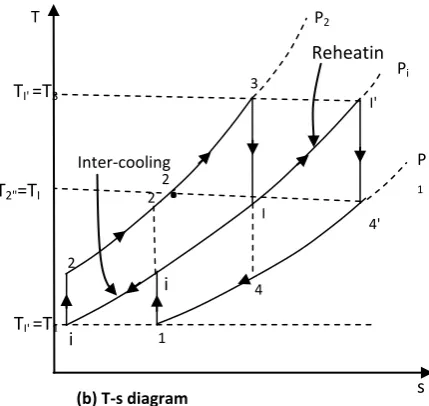
, Thus,Fig 4: Block and T-s diagrams of gas turbine engine cycle with Combination of all three modifications
2 1 2 1 ,2
1
1
reh th (26)The reheat cycle thermal efficiency, like in the cycle with inter-cooling, depends on both the pressure ratio and the temperature ratio.
2.4
Performance Analysis of Gas Turbine
Plant with Regeneration, Inter-cooling
and Reheat
A combination of all three modifications considered in the previous sections could be implemented in the gas turbine engine for the sake of performance improvement. The extent to which this new plant and every other plants’ improvements compare with each other and the simple cycle plant is presented in the next section. The block diagram and the T-s diagram of the plant is shown in Figure 4. The respective assumptions made in the regeneration, inter-cooling and reheat cycles are applicable here. The thermal efficiency of
the plant
th can easily be shown to be,
2 11
th (27)ere
1 3
T
T
and
1
p
r
.The thermal efficiency of the cycle depends on both the pressure ratio and the temperature ratio.
3.
PERFORMANCE OF THE
DIFFERENT MODIFIED CYCLES
To compare the performance of the different modified cycles with the simple cycle plant, the thermal efficiency of each plant is generated over a wide range of pressure ratios and the values obtained are compared. Another parameter to be compared is the specific fuel consumption (sfc) at different
Reheat er Regenerat or 4'
W
Turbine 1 I' I i ' 4Inter-cooler
C
C
3 2'
i
I’1
Comp 1 2Comp 2 Turbine 2
(a) Block diagram
CC
Inter-cooling
4
T
I'=T
3T
2"=T
I=T
4'T
I'=T
11
i
i
'
Ts
3 2 ' I 4' I' 2 2 " P2 Pi P 1Reheatin
g
.
[image:5.595.55.290.194.595.2]11 pressure ratios for each plant. The algorithm used for the
[image:6.595.325.530.76.218.2]analysis is shown in Figure 5 while a window for the selection of input data for the regeneration cycle using the developed software is presented in Figure 6.
Fig 6: Program window for input parameter selection
4.
SIMULATION RESULTS
[image:6.595.66.281.132.515.2]Figures 7 to 10 show respectively the variation of the thermal efficiencies of each of the modified cycles with pressure ratio.
Fig 7: Thermal efficiencies of the simple cycle and the regeneration cycle with pressure ratio
Fig 8:Thermal efficiencies of the simple cycle and the inter-cooled cycle with pressure ratio
[image:6.595.323.528.252.398.2]Fig 9:Thermal efficiencies of the simple cycle and the reheat cycle with pressure ratio
Fig 10:Thermal efficiencies of the simple Brayton cycle and the cycle with regeneration, inter-cooling and reheat
Fig 11: Compressor and turbine exit temperatures of simple and modified cycles
0 0.2 0.4 0.6 0.8 1
0 10 20 30 40 50
The
rmal
Ef
ficie
n
cy (
-)
Pressure ratio (-)
Simple cycle Regenerative cycle - Increasing T3/T1
0.15 0.3 0.45 0.6
0 10 20 30 40 50
The
rmal
e
ff
ici
e
n
cy
(-)
Pressure ratio (-)
Simple cycle
Cycle with inter-cooling-Increasing T3/T1
0.14 0.29 0.44 0.59
0 10 20 30 40 50
Th
erma
l Efficienc
y
(-)
Pressure Ratio (-)
Simple cycle
Reheat cycle - increasing T3/T1
0.15 0.3 0.45 0.6
0 10 20 30 40 50
The
rmal
Ef
ficie
n
cy (
-)
Pressure Ratio (-)
Simple cycle
0 400 800 1200
0 10 20 30 40 50
Temp
e
rature
(K)
Pressure ratio (-) T2, SC T2, IC
[image:6.595.323.525.423.558.2] [image:6.595.58.270.586.716.2]The thermal efficiency of the regeneration cycle plant decreases with pressure ratio but increases with the temperature ratio, T3/T1. This means regeneration is more effective for engines with low pressure ratios. The thermal efficiency of the regeneration cycle plant is higher than that of the simple cycle plant at lower pressure ratios. There is a pressure ratio at which the efficiencies of the two cycles are equal as in Figure 7. This is obtained mathematically by equating the efficiency terms of the two plants. That is,
reg th i th,
,
1
3 1 1
1
1
pr
pT
T
r
Solving, the pressure ratio is obtained in terms of the temperature ratio as,
1
2
1
3
T
T
r
p (33)This is the optimum pressure ratio (the pressure ratio at which the net work output is maximum presented in [1]). This pressure ratio serves as a guide in the system design process. Since at lower pressure ratios the regeneration cycle is of higher thermal efficiency than the simple cycle plant, regeneration plants can be designed for higher system performance but the additional cost of the recuperator should be considered in carrying out economic viability.
The thermal efficiency of the plant with inter-cooling increases with PR continuously like the simple cycle plant but lower than that of the simple cycle at all pressure ratios as shown in Figure 8. The thermal efficiency of the cycle with inter-cooling also increases with the temperature ratio, T3/T1. At higher pressure ratios, the simple cycle thermal efficiency is much greater than that of the intercooled plant. This means the gains from the lower compressor work are less than the additional energy requirement from the lower compressor exit temperature obtained. An inter-cooled plant is thus not suitable unless other form of modification is attached. The reheat plant thermal efficiency is similar to that of intercooled plant but of slightly lower magnitude at same pressure ratio and temperature ratio. Like the intercooled plant, the reheat plant should not be designed as a stand-alone modification to the simple cycle plant.
In the intercooled plant, the temperature at the exit of the second compressor is much lower than that obtained for a simple cycle plant as shown in Figure 11. For the reheat plant on the other hand, the exhaust gas temperature is much higher than that obtained for the simple cycle (see Figure 11). This high temperature exhaust gases (at lower pressure ratios) can be used to heat up the low temperature compressor exit gases in the cycle with cooling. Thus, combining the inter-cooling cycle and the reheat cycle with the regeneration cycle will be a good idea. The thermal efficiency of the cycle with all three combinations is similar to that of the regeneration cycle, but of higher magnitude at all pressure ratios and temperature ratios as shown in Figure 10.
For the cycle with all three modifications, the thermal efficiency of the plant is higher than that of the simple cycle plant at lower pressure ratios, but equals that of the simple cycle plant at a particular pressure ratio designated here as
m p
r
, . This pressure ratio increases with the temperature ratio and it is obtained by equating the thermal efficiencies of the two plants. This is given by Equation (34), 1
3 2
1 3 ,
T
T
r
p m (34)From Equation (34), for fixed value of T1, as T3 increases, the pressure ratio increases also and the cycle with all three modifications is of higher thermal efficiency over a large range of pressure ratios.
[image:7.595.326.548.431.589.2]The amount of heat input in the simple cycle decreases continuously with PR hence the thermal efficiency of this cycle increases continuously with PR also. The net work output of the regenerative cycle is the same as that of the simple cycle as the regeneration system does not affect the work terms of the cycle. The heat input into the regeneration cycle increases continuously with PR because the temperatures of the compressor exit gases and the turbine exit gases get closer with increase in PR. The thermal efficiency of the regeneration cycle thus decreases with PR. The net work outputs of both the intercooled cycle and the reheat cycle increases with PR while their respective heat inputs decreases with PR, although, that of the reheat cycle increases to a maximum and then decreases. This explains why the thermal efficiencies of these two cycles increase with PR. In the cycle with all modifications combined, both the net work output and the heat input increases with PR, but the latter increases at a greater rate. Thus the thermal efficiency of this cycle decreases gradually with PR.
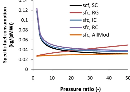
Fig 12: Specific fuel consumption of the different plants at different pressure ratios
The specific fuel consumption, sfc (in kg/sMW) of the various engine cycles at a given temperature ratio at different pressure ratios is presented in Figure 12. The sfc of the simple cycle engine (sfc, SC) is less than the sfc of the inter-cooled plant (sfc, IC) and that of the reheat plant (sfc, RC) indicating that more fuel is burnt in both the intercooled plant and reheat plant to produce a unit quantity of power compared to the simple cycle plant. Thus, intercooled plant and reheat plant are not suitable stand-alone modifications to the simple cycle plant. The sfc of all the three plants reduces with pressure ratio, as the compressor exit temperature increases with pressure ratio hence less fuel is burnt to attain the set TET at higher pressure ratios.
0 0.02 0.04 0.06 0.08 0.1 0.12 0.14
0 10 20 30 40 50
Sp
e
cific
fue
l co
n
su
mp
tion
(kg/(sMW))
Pressure ratio (-)
13 The sfc of the regeneration plant (sfc, RG) is less than that of
simple cycle plant at lower pressure ratios. It increases with the pressure ratio and becomes greater than that of the simple cycle at a particular pressure ratio. The behavior here is similar to that of the thermal efficiency and the sfc of the regeneration cycle equals that of the simple cycle at the optimum pressure ratio. The specific fuel consumption of the cycle with all three modifications (sfc, AllMod) is lower than that of the regenerative cycle at all pressure ratios. It increases with the pressure ratio and equals that of the simple cycle at a much higher pressure ratio given by Equation (34). This pressure ratio serves as a guide in the system design process.
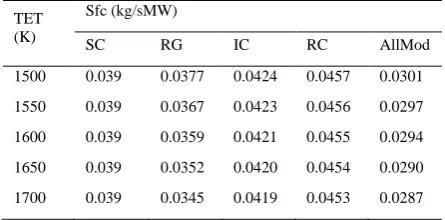
The results of the specific fuel consumption are obtained at a fixed temperature ratio. Assuming the ambient temperature is constant, the temperature ratio depends on the turbine entry temperature (TET) or T3. In this case, increase in TET means increase in temperature ratio. The specific fuel consumption decreases with increase in the temperature ratio or TET. For an ambient temperature of 301K and pressure ratio of 15.24:1, the sfc of the various cycles at different TET values are as shown in Table 1.
Table 1: sfc of various engine cycles at different TET values
TET (K)
Sfc (kg/sMW)
SC RG IC RC AllMod
1500 0.039 0.0377 0.0424 0.0457 0.0301
1550 0.039 0.0367 0.0423 0.0456 0.0297
1600 0.039 0.0359 0.0421 0.0455 0.0294
1650 0.039 0.0352 0.0420 0.0454 0.0290
1700 0.039 0.0345 0.0419 0.0453 0.0287
The simple cycle plant sfc remains constant as the sfc is derived from the thermal efficiency and the thermal efficiency of the ideal simple cycle plant depends on the pressure ratio only. The regenerative cycle plant responds more to change in temperature ratio followed by the cycle with all modifications with percentage decrease in sfc in the given range as 8.39% and 4.714% respectively. These two cycles utilize the higher temperature values due to increase in TET to heat up the compressor exit gases hence the greater response of their sfc to increase in TET.
5.
CONCLUSIONS
In this research, gas turbine performance analysis software developed and validated in a previous work is applied to modified gas turbine engine cycles to compare the performance of the different modified cycles over a range of pressure ratios. The modified cycles considered are the regeneration cycle, intercooled cycle, reheat cycle, and the cycle with all three modifications combined. The thermal efficiency of the regeneration cycle plant decreases with pressure ratio. It is greater than the thermal efficiency of the simple cycle plant at lower pressure ratios and equals that of the simple cycle plant at the optimum pressure ratio. For the inter-cooled cycle plant employing two compressors, the thermal efficiency increases with PR, but always less than that of the simple cycle plant. Thus, intercooling is not a suitable stand-alone modification to the simple cycle plant. The reheat cycle thermal efficiency is less than that of the intercooled cycle at all pressure ratios; reheating is thus not a suitable stand-alone modification to the simple cycle plant. The plant with all three modifications combined gives the highest
thermal efficiency, it decreases with PR and gets to that of the simple cycle at a PR much greater than the optimum PR. The specific fuel consumption of each plant behaves like the thermal efficiency values in terms of response to increase in PR. The sfc of the intercooled and reheat plants are greater than the sfc of the simple cycle plant at all pressure ratios, and they all decrease with PR. The sfc of the regeneration cycle and the cycle with all three modifications combined are less than that of the simple cycle plant at lower pressure ratios, they both increase with PR become greater than the sfc of the simple cycle plant at different pressure ratios. The cycle with all three modifications combined has lower sfc compared to the regeneration plant. At a fixed ambient temperature, the sfc of all the modified cycles decreases with the TET, but the regenerative cycle plant responds to the increase in TET greatly followed by the cycle with all three modifications combined. The cycle with all three modifications combined is the most suitable but the cost of all the three additional units to the simple cycle plant should be considered in carrying out economic analysis of this plant compared to the simple cycle plant. The developed software can be used extensively in studying the behaviour of the different modified cycles and can serve as a preliminary design tool.
6.
REFERENCES
[1] E. G. Saturday and J. C. Ofodu, ―Development and Application of Gas Turbine Performance Analysis Software : Part I- Ideal Cycles and Real Cycles,‖ vol. 180, no. 37, pp. 20–26, 2018.
[2] K. Ashok, S. S. Kachhwaha, and R. S. Mishra, ―Thermodynamic Analysis of a Regenerative Gas Turbine Cogeneration Plant,‖ J. Sci. Ind. Res., vol. 69, pp. 225–231, 2010.
[3] R. Ranjan and M. Tariq, ―Analysis of a Regenerative Gas Turbine Cycle for Performance Evaluation,‖ vol. 2, no. 4, pp. 792–801, 2014.
[4] H. Omar, A. Kamel, and M. Alsanousi, ―Performance of Regenerative Gas Turbine Power Plant,‖ pp. 136– 146, 2017.
[5] W. Hussein and A. Razzaq, ―Parametric Performance of Gas Turbine Power Plant with Effect Intercooler,‖ Mod. Appl. Sci., vol. 5, no. 3, pp. 173–184, 2011. [6] T. K. Ibrahim, M. M. Rahman, and A. N. A. Alla,
―Study on the Effective Parameter of Gas Turbine Model with Intercooled Compression Process,‖ Sci. Res. Essays, vol. 5, no. 23, pp. 3760–3770, 2010. [7] I. G. Rice, ―The Combined Reheat Gas Turbine /
Steam Turbine Cycle Part || — The LM 5000 Gas Generator Applied to the Combined Reheat Gas Turbine / Steam,‖ J. Eng. Power, vol. 102, pp. 42– 49, 1980.
[8] M. S. Patil, D. B. Pawase, and E. R. Deore, ―Thermal Performance of Reheat , Regenerative , Inter Cooled Gas Turbine Cycle,‖ IJRMET, vol. 5, no. 2, pp. 28– 33, 2015.
[9] M. J. Mohammed and M. Tariq, ―Analysis of a Combined Regenerative and Reheat Gas Turbine Cycle using MATLAB,‖ Int. J. Sci. Eng. Technol. Res., vol. 3, no. 4, pp. 665–672, 2014.
[image:8.595.57.280.323.433.2]pp. 43–54, 2013.
[11] R. Andriani, F. Gamma, and U. Ghezzi, ―Main Effects of Intercooling and Regeneration On Aeronautical Gas Turbine Engines,‖ in 46th AIAA/ASME/SAE/ASEE Joint Propulsion Conference & Exhibit 25 - 28 July 2010, Nashville, TN, 2010, no. July, pp. 1–8.
[12] Y. A. Cengel and M. A. Boles, Thermodynamics: An Engineering Approach, 5th ed. NY: McGraw-Hill, 2009.