Voice/Fax Over IP Networks
Model MVP200
88310302 Revision C MultiVOIP 200 (Model MVP200)
This publication may not be reproduced, in whole or in part, without prior expressed written permission from Multi-Tech Systems, Inc. All rights reserved.
Copyright © 1999, by Multi-Tech Systems, Inc.
Multi-Tech Systems, Inc. makes no representations or warranties with respect to the contents hereof and
specifically disclaims any implied warranties of merchantability or fitness for any particular purpose. Furthermore, Multi-Tech Systems, Inc. reserves the right to revise this publication and to make changes from time to time in the content hereof without obligation of Multi-Tech Systems, Inc. to notify any person or organization of such
revisions or changes.
Record of Revisions
Revision Description
C Manual revised; covers software version 2.01. All pages at revision C. (4/27/99)
Patents
This Product is covered by one or more of the following U.S. Patent Numbers: 5.301.274; 5.309.562; 5.355.365;
5.355.653; 5.452.289; 5.453.986. Other Patents Pending.
TRADEMARK
Trademark of Multi-Tech Systems, Inc. is the Multi-Tech logo. Windows is a registered trademark of Microsoft.
Multi-Tech Systems, Inc. 2205 Woodale Drive Mounds View, Minnesota 55112 (612) 785-3500 or (800) 328-9717
Fax 612-785-9874 Tech Support (800) 972-2439
Fax-Back (612) 717-5888
Contents
Chapter 1 - Introduction and Description
Introduction ... 6
Preview of this Guide ... 7
Typical Application ... 8
Front Panel Description ... 11
Back Panel Description ... 12
Power Connector ... 12
Command Connector ... 12
10Base-T (Ethernet) Connector ... 12
Voice/Fax Channel 1 and 2 ... 12
Specifications ... 13
Ethernet Port ... 13
Command Port ... 13
Voice/Fax Channel 1 and 2 ... 13
Electrical/Physical ... 13
Chapter 2 - Installation
Installing Your MultiVOIP ... 16Unpacking Your MultiVOIP ... 17
Safety Warnings ... 17
Telecom ... 17
Cabling Your MultiVOIP ... 18
Cabling Procedure ... 18
E&M Jumper Block Positioning Procedure ... 20
Chapter 3 - Software Loading and Configuration
Installing Your MultiVOIP Software ... 22Phase 1: Configuring Your Master MultiVOIP ... 22
Phase 2: Configure Your Slave MultiVOIPs ... 32
Phase 3: Deploy the VOIP Network ... 37
Chapter 4 - MultiVOIP Software
Introduction ... 40Before You Begin ... 40
MultiVOIP Configuration ... 41
Changing Channel Parameters ... 42
Interface ... 42
Voice/Fax ... 43
Regional ... 44
Changing the Phone Directory Database ... 45
Changing IP Parameters ... 47
ProxyServer ... 47
Viewing Statistics ... 49
IP Statistics ... 49
SNMP Statistics ... 50
Viewing Logs ... 50
Reports ... 52
Others Setup ... 53
Viewing Call Progress ... 54
Upgrade Procedures ... 55
Download Firmware ... 55
Introduction ... 58
Remote Configuration ... 58
Modem-Based ... 58
LAN-Based ... 60
Remote Management ... 62
Telnet ... 62
WEB Management ... 64
Chapter 6 - Warranty, Service and Tech Support
Introduction ... 66Limited Warranty ... 66
On-line Warranty Registration ... 66
Service ... 67
Tech Support ... 67
Recording MultiVOIP Information ... 67
The Multi-Tech BBS ... 68
To Log on to the Multi-Tech BBS ... 68
To Download a File ... 68
About Multi-Tech’s Internet Presence ... 70
About the Multi-Tech Fax-Back Service ... 70
Appendixes
Appendix A - TCP/IP (Transmission Control Protocol/Internet Protocol) Description ... 72Appendix B - Cabling Diagrams ... 75
Appendix C - Regulatory Information ... 77
Glossary
Introduction
Welcome to Multi-Tech's new voice/fax gateway, the MultiVOIP, model MVP200. The MultiVOIP allows analog voice and fax communication over a traditional data communications/data networking digital Internet. Multi-Tech’s new voice/fax gateway technology allows voice and fax communication to ride, with no additional expense, over your existing communications Internet, which has
traditionally been data-only. To access this free voice and fax communication, all you have to do is connect the MultiVOIP to a phone or to your existing in-house phone switch, and then to your existing Internet connection. Once configured, the MultiVOIP then allows voice and fax to travel down the same path as your traditional data communications.
The MVP200 is designed with two voice/fax channels (which offer three voice/fax interfaces on each channel), a 10 Mbps Ethernet LAN interface, and a command port for configuration. System
management is provided through the command port using bundled Windows® software which provides easy-to-use configuration menus and a comprehensive online Help system.
Voice / Fax over IP Networks
Preview of this Guide
This guide describes the MultiVOIP and tells you how to install and configure the unit. The information contained in each chapter is as follows:
Chapter 1 - Introduction and Description
Chapter 1 describes the MultiVOIP. Front panel indicators, and back panel connector descriptions are provided. In addition, a list of relevant specifications is provided at the end of the chapter.
Chapter 2 - Installation
Chapter 2 provides information on unpacking and cabling your MultiVOIP. The installation procedure
describes each cable connection.
Chapter 3 - Software Loading and Configuration
Chapter 3 provides instructions for software loading and initial configuration. The MultiVOIP software
disks are Windows® based. Later chapters, as well as the online Help, describe the MultiVOIP software in more detail.
Chapter 4 - MultiVOIP Software
Chapter 4 describes the MultiVOIP software package designed for the Windows ® environment. This
chapter describes the software from an applications standpoint, and in so doing, not every screen is shown, nor is each field within a screen defined. For explanations and parameters of each field within a dialog box, refer to the Help.
Chapter 5 - Remote Configuration and Management
Chapter 5 provides procedures for changing the configuration of a remote MultiVOIP. Remote
configuration enables you to change the configuration of a unit by simply connecting two modems between the two MultiVOIPs and remotely controlling the unit. Chapter 5 also describes typical client applications (i.e., Telnet and Web-based management) used for remote configuration of the
MultiVOIP.
Chapter 6 - Warranty, Service and Tech Support
Chapter 6 provides instructions on getting service for your MultiVOIP at the factory, a statement of
Typical Application
Before Voice Over IP (VOIP), voice over the Internet, a corporate office had a data connection to the Internet and a voice connection to the public telephone network. With VOIP, the two networks can be tied together. To accomplish this, a MultiVOIP is connected between the public telephone network and the data network. A typical application for a MultiVOIP is shown in Figure 1-2.
Remote Branch Office Internet/Intranet IP Network Corporate Office P B X PSTN Connection (T1/E1, PRI, etc.)
Web Server Workstation Workstation MultiVOIP IP Address 204.22.122.118 Mask 255.255.255.128 LAN ISP PSTN Workstation Workstation LAN Analog Connections
Channel 1: FXO Channel 2: FXO
Router
IP Address 204.22.122.1 Mask 255.255.255.128
MultiVOIP
IP Address 202.54.39.100 Mask 255.255.255.240
ProxyServer IP Address 202.54.39.97 Mask 255.255.255.240
#301
#302
ProxyServer Static IP Address 209.96.211.90 512-4122 512-4123 4124 102 101 Router 4125 Proxy Server HUB HUB
Figure 1-2. Typical VOIP Application
Now, to set up the VOIP network, a MultiVOIP at the corporate office is connected between the data network and the corporate telephone switch (PBX). To connect the MultiVOIP to the data network, an Ethernet cable is connected to the Ethernet port on the MultiVOIP and the other end of the cable is plugged into a hub on the data network. On the phone side, two phone cables are connected to the FXO jacks on the back of the MultiVOIP and run to two station lines on the phone switch. These two lines on the PBX occupy phone extensions 4124 and 4125.
To set up a MultiVOIP at the remote branch office, the Ethernet jack on the MultiVOIP is connected to the hub and two phone cables are connected between the FXS jacks on the MultiVOIP and two analog phones.
The unique feature here is that both channels do not have to be configured the same way. One channel could be connected to an extension line off the phone switch and the other channel
connected directly to your fax machine. In this situation, you would use the FXS interface which has two options—loop start and ground start. Loop start is generally the correct interface to use.
If you want a user to be able to call into a facility and then use the local phone capability to dial out to the public phone network, you can chose either the FXO or E&M interface. If you chose the FXO interface, you can connect to the station side of your phone switch and be able to use all the features of your local phone system. If you want to call out on the local phone network while you are at a remote branch office, you would dial the MultiVOIP at the corporate facility and then dial an outside line to access the local phone network.
If you use the E&M interface, you have more control over call management. The E&M connection uses the trunk side of the phone switch; therefore, to access a trunk line, you would dial the trunk’s access number instead of an extension number. Also, the E&M interface has five signaling types that are supported by the MultiVOIP.
Before you construct the phone directory database, you must establish the Master-Slave relationship between MultiVOIPs, which enables one MultiVOIP (the “Master”) to control the database. The database defines each phone number that can be dialed on the VOIP network. Each phone number entry in the database identifies a phone connection. For example, Station Phone Number 101 is at the corporate office. This phone number is connected to voice/fax channel 1 on the corporate office MultiVOIP. Voice/fax channel 1 is connected to extension 4124 on the corporate phone switch. So if a person in the corporate facility wants to access the VOIP network, they would merely dial extension 4124. However, if someone at the remote branch office wants to access the corporate phone system, they have to dial Station Phone Number 101.
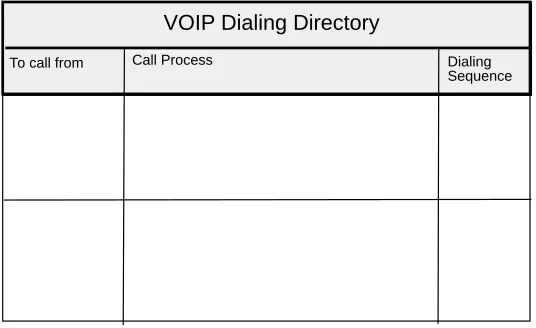
From the phone directory database you can build your VOIP dialing directory. For example, a corporate user picks up a phone in his/her office and dials extension 4124. This connects them to channel 1 on the corporate MultiVOIP. A second dial tone is heard, and they then dial VOIP
extension 301 which connects them to the remote branch office and enables a voice conversation to take place over the VOIP network.
Similarly, a remote branch office employee can pick up the phone at 301 and dial VOIP extension 102. This routes the call to the corporate office MultiVOIP where a second dial tone is heard; the remote branch office employee then dials extension 4122 and a conversation can take place between the two phones.
To call from Call Process
Pick up telephone and dial an extension number (e.g., 4124 or412 5).
Second dial tone is generated, dial the Remote Branch Office MultiVOIP (201).
Dialing Sequence
4124
301
Pick up telephone and dial 101 or 102. A second dial tone is generated, dial 4122 or for the fax 4123.
101
4124
VOIP Dialing Directory
Front Panel Description
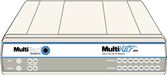
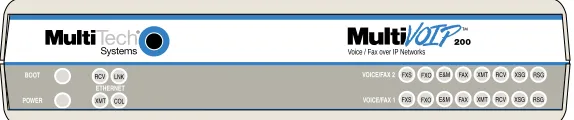
The front panel has three groups of LEDs that provide the status of the Ethernet connection (Ethernet), Voice/Fax channels (Voice/Fax 1 and 2), and general status of the MultiVOIP (Boot and Power). The front panel is shown in Figure 1-3, and a description of each LED follows.
Voice / Fax over IP Networks
Figure 1-3. Front Panel
Ethernet
RCV Receive Data: Indicator blinks when packets are being received from the local area network.
XMT Transmit Data: Indicator blinks when packets are being transmitted to the local area network.
LNK Link: Indicator lights when the Ethernet link senses voltage from a concentrator or external
device.
COL Collision: Indicator lights when a collision is detected on the Ethernet link.
Voice/Fax 1 and 2
FXS Foreign Exchange Station: Indicator lights when the voice/fax channel is configured for FXS
operation.
FXO Foreign Exchange Office: Indicator lights when the voice/fax channel is configured for FXO
operation.
E&M Ear & Mouth: Indicator lights when the voice/fax channel is configured for E&M operation.
FAX Fax: Indicator lights when there is fax traffic on the voice/fax channel.
XMT Transmit: Indicator blinks when voice packets are being transmitted to the local area network.
RCV Receive: Indicator blinks when voice packets are being received from the local area network.
XSG Transmit Signal: Indicator lights when the FXS-configured channel is off-hook, the
FXO-configured channel is receiving a ring from the Telco, or the M lead is active on the E&M configured channel.
RSG Receive Signal: Indicator lights when the FXS-configured channel is ringing, the
FXO-configured channel has taken the line off-hook, or the E lead is active on the E&M-FXO-configured channel.
Boot
The Boot indicator lights when the MultiVOIP is booting or downloading setup.
Power
Back Panel Description
The cable connections for the MultiVOIP are made at the back panel. Connectors include Power, Command Port (RS-232), Ethernet (10Base-T), Voice/Fax Channels 1 and 2 (E&M, FXO and FXS). The cable connectors are shown in Figure 1-4 and defined in the following groups.
VOICE/FAX CHANNEL 2
E&MFXO FXS
VOICE/FAX CHANNEL 1
E&MFXO FXS
ETHERNET RS232
COMMAND 10BASE-T
I
O
GND
POWER
Figure 1-4. Back Panel
Power Connector
The Power connector is used to connect the external power supply to the MultiVOIP. The Power connector is a 7-pin circular DIN connector. A standard computer power cord connects the power supply to a live AC grounded outlet.
Command Connector
The Command connector is used to configure the MultiVOIP using a PC with an available serial port and running Windows® software. The Command connector is an RJ-45 jack, and an adapter cable is provided to convert to a standard serial port DB-9 female connector.
10Base-T (Ethernet) Connector
The Ethernet 10Base-T connector is used to connect the MultiVOIP to a LAN using unshielded twisted cable. This connector is an RJ-45 jack.
Voice/Fax Channel 1 and 2
The Voice/Fax Channel connectors include three options per channel: E&M, FXS and FXO. E&M - This connector is used for connecting Voice/Fax Channel 1 or 2 to the E&M trunk on a PBX. This connector is an RJ-45 jack.
FXS - This connector is used for connecting Voice/Fax Channel 1 or 2 to a station device; e.g., an analog phone, a KTS phone system, or a fax machine. This connector is an RJ-11 jack.
Specifications
• One 1 Meg by 32 byte at 70 nanosecond SIMM is 4 Mb DRAM Caution: SIMM speed and size cannot be mixed
• Two Meg of flash memory
Ethernet Port
• Single Ethernet Interface - 10Base-T (twisted pair) keyed RJ-45 connector.
Command Port
• Single 19.2K bps asynchronous Command Port using an RJ-45 to DB-9 cable with a DB-9 female connector
Voice/Fax Channel 1 and 2
• Two RJ-11 jacks (FXO and FXS) • One RJ-45 jack (E&M)Electrical/Physical
• Voltage: 115 VAC (Standard), 240 Volts AC (Optional)
• Frequency: 47 to 63 Hz
• Power Consumption: 18 Watts
• Dimensions: 2.25" high x 9" wide x 12.875" deep (5.72 cm x 22.86 cm x 32.70 cm)
Installing Your MultiVOIP
The basic steps of installing your MultiVOIP network involve unpacking the units, connecting the cables, and configuring the units using the included management software (MultiVOIP Configuration). The recommended installation process includes three phases that, when completed, result in a fully functional Voice Over IP network. A general description of each phase is provided below, and detailed instructions follow throughout the rest of this chapter and Chapter 3.
Phase 1: Configure and Install Your Master MultiVOIP
As the first step, the VOIP administrator configures the MultiVOIP designated as the “Master” unit. This includes the assignment of a unique LAN IP address, subnet mask, and Gateway IP address; as well as the selection of appropriate channel interface type for each of the Voice/Fax channels. Once all connections have been made, the VOIP administrator configures the unit and builds the Phone Directory Database that will reside with the Master unit.
Phase 2: Configure Your Slave MultiVOIP(s)
Once Phase 1 has been completed, the administrator moves on to configure the MultiVOIP(s) designated as “Slave” units. Again, unique LAN IP addresses, subnet masks, and Gateway IP addresses are assigned, and each Voice/Fax channel is configured for the appropriate channel interface type. When this is done, the Phone Directory Database option is set to Slave, and the IP address of the Master MultiVOIP is entered. Once all Slave units are configured, the process moves on to Phase 3.
Phase 3: Deploy the VOIP Network
The final phase of the installation is deployment of the network. Through the first two phases, the VOIP administrator controls configuration, so when the Slave MultiVOIPs are sent to their remote sites, the remote site administrators need only to connect the units to their LAN and telephone equipment. A full Phone Directory Database (supplied by the Master MultiVOIP) will be loaded into their unit within minutes of being connected and powered up.
Unpacking Your MultiVOIP
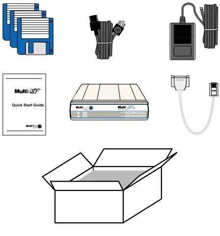
Remove all items from the box.
Voice / Fax over IP Networks
Figure 2-1. Unpacking
Safety Warnings
Caution: Danger of explosion if battery is incorrectly replaced.
A lithium battery on the voice/fax channel board provides backup power for the time keeping capability. The battery has an estimated life expectancy of ten years.
When the battery starts to weaken, the date and time may be incorrect. If the battery fails, the board must be sent back to Multi-Tech Systems for battery replacement.
The E&M, FXS, and Ethernet ports are not designed to be connected to a Public Telecommunication Network.
Telecom
1 Never install phone wiring during a lightning storm.
2 Never install phone jacks in wet locations unless the jacks are specifically designed for wet locations.
3 This product is to be used with UL and cUL listed computers.
4 Never touch uninsulated phone wires or terminals unless the phone line has been disconnected at the network interface.
5 Use caution when installing or modifying phone lines.
6 Avoid using a phone (other than a cordless type) during an electrical storm. There may be a remote risk of electrical shock from lightning.
7 Do not use the phone to report a gas leak in the vicinity of the leak.
Cabling Your MultiVOIP
Cabling your MultiVOIP involves making the proper Power, Command Port, and Internet connections. Figure 2-2 shows the back panel connectors and the associated cable connections. The Cabling Procedure has step-by-step instructions for cabling your MultiVOIP.
FXS E&M
FXO
Ethernet Connection
Command Port Connection
Power Connection PSTN
VOICE/FAX CHANNEL 2
E&MFXO FXS
VOICE/FAX CHANNEL 1
E&MFXO FXS ETHERNET RS232 COMMAND 10BASE-T I O GND POWER
Voice/Fax Channel 1 & 2 Connections
Figure 2-2. Cable Connections
Cabling Procedure
1 If you are connecting any Voice/Fax Channel to an E&M trunk other than type 2, perform the E&M Jumper Block Positioning procedure before connecting power to the unit.
2 Connect the power supply to a live AC outlet, then connect the other end to the MultiVOIP as shown in Figure 2-2. The power connector is a 7-pin circular DIN connector.
3 Connect the MultiVOIP to a PC by using the RJ-45 to DB-9 (female) cable provided with your unit. Plug the RJ-45 end of the cable into the Command port of the MultiVOIP and the other end to the PC serial port. See Figure 2-2.
4 Connect a network cable to the Ethernet 10Base-T connector on the back of the MultiVOIP. Connect the other end of the cable to your network.
If you are connecting a PBX extension to your MultiVOIP, connect one end of an RJ-11 phone cord to the Voice/Fax Channel 1 FXO connector on the back of the MultiVOIP and the other end to the PBX extension.
If you are connecting an E&M trunk from a telephone switch to your MultiVOIP, connect one end of an RJ-45 phone cord to the Voice/Fax Channel 1 E&M connector on the back of the MultiVOIP and the other end to the trunk. Refer to Appendix B for connector drawings. 6 Repeat the above step to connect the remaining telephone equipment to each Voice/Fax
Channel on your MultiVOIP.
7 Turn on power to the MultiVOIP by placing the ON/OFF switch on the back panel to the ON position. Wait for the BOOT LED on the MultiVOIP to go OFF before proceeding. This may take a couple of minutes.
E&M Jumper Block Positioning Procedure
A jumper block exists for each voice/fax channel. The jumper block is to the right of each set of channel jacks. The jumper block contains 8 pairs of pins. The jumper plug fits over three pairs of pins on the jumper block. The E&M type number is labeled on the PC board. The jumper plug needs to be centered on the E&M type number. Perform the following procedure to change E&M jumper position. 1 Ensure that power is removed from the MultiVOIP
2 Remove the two phillips screws on the bottom of the cover. 3 Slide the cover forward to expose the MultiVOIP circuit board.
4 To change a jumper position, lift the jumper plug up off the jumper block and move to the new position, ensuring that the center jumper is centered on the E&M type number.
4
2 (Default)
1,3
Back
5
5 Change the jumper position for each voice/fax channel that is connecting to an E&M trunk that is not a type 2.
6 Slide the cover back on to the chassis. 7 Replace the two phillips screws.
Installing Your MultiVOIP Software
The following installation procedure does not provide every screen or option in the process of installing the MultiVOIP software. The assumption is that a technical person with a thorough knowledge of Windows and the software loading process is doing the installation. Additional
information on the MultiVOIP software is provided in the Chapter 4 - MultiVOIP Software, as well as in the Help system.
Phase 1: Configuring Your Master MultiVOIP
Configuring your Master MultiVOIP involves software loading and configuration.
Software Loading
The software loading procedure does not provide every screen or option in the loading process. It is assumed that a technical person with a thorough knowledge of Windows and the software loading process is performing the installation. Additional information on the MultiVOIP software is provided in the User Guide supplied with your MultiVOIP.
If you are installing a MultiVOIP behind a firewall, you need to add the following UDP ports to your firewall.
Q.931 Signaling, Ch1 [900] Q.931 Signaling, Ch2 [902] Status [5000]
Ch1 RTP [5004] Ch1 RTCP [5005] Ch2 RTP [5006] Ch2 RTCP [5007]
Refer to your firewall user documentation to enter and open these ports. 1 Run Windows on the PC connected to the MultiVOIP.
2 Insert the MultiVOIP diskette labeled Disk 1 into the disk drive on the PC connected to the MultiVOIP.
3 Win3.1 users - in Program Manager, click File | Run. In the Run dialog box, type a:\setup
or b:\setup (depending on the location of your floppy disk drive) in the Command Line field and then click OK.
Win95/98/NT users - click Start | Run. In the Run dialog box click the down arrow and
choose a:\setup or b:\setup (depending on the location of your floppy disk drive), then click OK.
5 Follow the on-screen instructions to install your MultiVOIP software.
6 The following dialog box selects the COM port of your PC connected to the Command port of the MultiVOIP. From the Select Port drop-down list, choose the COM port of your PC.
Click OK to continue.
7 The Setup Complete dialog is displayed.
8 The following message is displayed:
Click Yes to continue.
9 The following dialog box is displayed.
Click Yes to continue.
10 The IP Protocol Default Setup dialog box is displayed.
The default Frame Type is TYPE_II. If this does not match your IP network, change the Frame Type by clicking on the drop down box. The Frame Type choices are TYPE_II and SNAP.
11 In the Ethernet group, enter your unique LAN IP address in the IP Address field. Then enter the Subnet Mask and Gateway Address for your LAN in the corresponding fields.
The IP address is your unique LAN IP address, and the Gateway address is the IP address of the device connecting your MultiVOIP to the Internet.
12 The Channel Setup dialog box is displayed. The three tabs in this dialog are used to define the voice/fax channel interface, voice coder, fax parameters, and regional phone parameters (tone pairs) for each channel.
Configure each channel for the type of interface you are connecting to. The Interface tab defaults to Channel 1 in the Select Channel field. To change the channel number, click the drop-down arrow and the list of channels is displayed. Highlight the channel you want to configure.
13 The Interface group defaults to FXS (Loop Start). Select the interface option that
corresponds to the interface type being connected to the Voice/Fax Channel 1 jack on the back panel of the MultiVOIP.
If you are connected to a station device; e.g., an analog telephone, fax machine, or Key Telephone System (KTS) to the Voice/Fax connector on the back of the unit, FXS (Loop Start) will likely be the correct Interface option.
If the station device uses ground start, then choose the FXS (Ground Start) option. Refer to the device’s user documentation.
If you are using an analog extension from your PBX, then choose the FXO option. Check with your in-house phone personnel to verify the connection type.
If you are connecting to an analog E&M trunk on your PBX, then choose the E&M option. If you choose the FXO interface, the Dialing Options Regeneration group is enabled. Check with your local in-house phone personnel to verify whether your local PBX dial signaling is Pulse or tone (DTMF). Then, set the Regeneration option accordingly.
For FXO-to-FXO communications, you can enable a specific type of FXO Disconnect --either current loss, tone detection, or silence detection (Check with your in-house phone personnel to verify the preferred type of disconnect to use). For tone detection, you can select from drop-down lists either one or two DTMF tones that will cause the line to be disconnected; the person hanging up a call must then hit the key(s) that will produce those tones. For silence detection, select One Way or Two Way, then set the timer for the number of seconds of silence before disconnect.
If you choose the E&M interface, the E&M Options group is enabled. Check with your local in-house phone personnel to determine if the signaling is Dial Tone or Wink and if the connection is 2-wire or 4-wire. If Wink signaling is used, then the Wink Timer is enabled with a default of 250 milliseconds. The range of the Wink Timer is from 100 to 350 milliseconds. Consult with your local in-house phone personnel for this timer setting.
If you want to dedicate a local voice/fax channel to a remote voice/fax channel (so you will not have to dial the remote channel), click the Auto Call Enable option in the Auto Call group. Then enter the appropriate phone number in the Phone Number field.
Note: After configuring a given channel (1 or 2), you can copy that channel’s configuration to the other channel by clicking the Copy button. Everything on the Interface tab will be copied to the other channel.
14 Repeat the above step to configure the interface type for voice/fax Channel 2.
15 The Voice/Fax tab displays the parameters for the voice coder, faxing, DTMF gain, billing charges for inbound and/or outbound calls, password authentication on inbound and/or outbound calls, and auto disconnect which limits call duration.
16 To change the voice coder, first select the channel by clicking the Select Channel down arrow and highlighting the channel number, then click the Voice Coder down arrow and highlight your new voice coder entry.
If you changed the voice coder, ensure that the same voice coder is used on the voice/fax channel you are calling; otherwise, you will always get a busy signal.
17 If you selected the FXO interface and are using touchtone dialing, you can set up the DTMF gain (or output level in decibels - dB) for the higher and lower frequency groups of the DTMF tone pair.
Note: Only change the DTMF gain under the direction of Multi-Tech Tech Support.
Make your selections in the drop-down lists in the DTMF Gain group.
19 You can set up billing options for inbound and/or outbound calls by checking them in the Billing Options group and then typing in the charge in cents per x seconds.
20 Password protection can be enabled for outbound and/or inbound calls on the selected voice/ fax channel. If you enable password Authentication on inbound or outbound calls, you need to also enter a password of up to 14 numeric characters in the Password field.
A user attempting to access the voice/fax channel will be repeatedly prompted with a series of two short tones. At this point they must enter the password from their DTMF keypad to access the voice/fax channel.
21 The Automatic Disconnect option limits call duration to the number of seconds entered in the Timer: (sec) field. The default value of 15 seconds can be changed to any other value up to 65,535 (roughly 18.2 hours).
Note: After configuring a given channel (1 or 2), you can copy that channel’s configuration to the other channel by clicking the Copy button. Everything on the Voice/Fax tab will be copied to the other channel.
If your country/region is not the default USA, click the Regional tab and proceed to step 22; otherwise, proceed to step 23 to begin building your phone directory database.
22 To change the Tone Pairs on the Regional tab, click the Country/Region down arrow and highlight your specific country or region.
23 The Phone Directory Database dialog box is displayed. You will build your personalized MultiVOIP Phone Directory in the following steps.
The MultiVOIP configured as a “Master” will contain the master database. The master database has the phone numbers of all the MultiVOIP’s available for communication on an IP network. This database is downloaded to each Slave MultiVOIP as it comes online.
Click Add (+) to begin building your phone directory database. 24 The Add/Edit Phone Entry dialog is displayed.
In the Station Information group, enter the unique phone number of the local device connected to Channel 1 in the Phone Number field (for example phone number 101). 25 The Description field is optional, but can be useful in associating the channel to the
extension. If you wish, enter a description of your local phone number. This description serves to identify the phone number you entered in the previous step (for example, “Jerry’s Desk”).
26 The Permit Hunting option enables the answering unit to roll over to a second channel if the first channel is busy. Click Permit Hunting if you want the calls to roll over to a second voice/ fax channel.
27 In the MultiVOIP Identification group, enter the IP address of the Master MultiVOIP in the IP Address field. For example, 204.22.122.118. Then obtain the 12-digit Node ID#
(0008005xxxxx) from the ID plate on the back panel of the MultiVOIP and enter this number in the Ethernet Node ID field. If the ID plate is missing or damaged, you can also Telnet to the MultiVOIP and, on the MultiVOIP Telnet Server menu enter 1 to advance to the Main Menu, then enter 3 for System Information where item 1 is the Ethernet Port Address you want to enter in the Ethernet Node ID field.
28 Click OK and you are returned to the Phone Directory Database dialog box, which now includes phone number 101 with its IP address, channel number and description.
29 Click Add (+) and the Add/Edit Phone Entry dialog box is displayed again.
30 Enter the phone number for the remote MultiVOIP in the Station Information group Phone Number field. For example, 201.
31 Click the Description field and enter a description for the remote MultiVOIP phone number for Channel 1. For example, “Hari’s Office.”
32 Enter the IP address of the remote MultiVOIP in the IP Address field in the MultiVOIP Identification Group. For example, 202.56.39.100.
33 Click OK and you are returned to the Phone Directory Database dialog box, which now includes the second number and related information in the Phone Number list.
Note: If only Channel 1 is active, you must enter two phone numbers. The first number will be the local MultiVOIP phone number for Channel 1, and the second number will be the remote MultiVOIP phone number for Channel 1.
If both Channels 1 and 2 are active, four phone numbers will have to entered.
34 When you have finished, click OK to download the setup configuration to the MultiVOIP. 35 The Checking MultiVOIP dialog box is displayed.
36 The Writing Setup dialog box is displayed as the setup configuration is written to the MultiVOIP.
37 After the setup is written to the MultiVOIP, the unit is rebooted.
38 Check to ensure that the BOOT LED on the MultiVOIP is Off after the download is complete. This may take several minutes as the MultiVOIP reboots.
39 Win3.1 users - you are returned to your Program Manager where the MultiVOIP Program Group and Program Items (Windows icons) are displayed.
Win95/98/NT users - you are returned to your MultiVOIP folder which is open and visible on your desktop.
Phase 2: Configure Your Slave MultiVOIPs
If you are installing a MultiVOIP behind a firewall, you need to add the following UDP ports to your firewall.
Q.931 Signaling, Ch1 [900] Q.931 Signaling, Ch2 [902] Status [5000]
Ch1 RTP [5004] Ch1 RTCP [5005] Ch2 RTP [5006] Ch2 RTCP [5007]
Refer to your firewall user documentation to enter and open these ports.
1 Disconnect the PC from the command port of the Master MultiVOIP and connect it to the command port on the Slave MultiVOIP.
2 Win 3.1 users - from the Program Manager, click the MultiVOIP Configuration icon in the MultiVOIP Program Group. The main menu is displayed.
Win95/98/NT users - from your desktop, click Programs I MultiVOIP I MultiVOIP Configuration. The main menu is displayed.
3 Click IP and the IP Setup dialog box is displayed.
4 In the Port Address group, enter the IP Address and IP Mask. In the Gateway Address group, enter the gateway IP address for the slave unit.
The IP address is your unique LAN IP address, and the Gateway address is the IP address of the device connected to the Internet/Intranet.
Click OK when you are finished. The main menu is displayed.
5 From the main menu, click Voice Channels and the Channel Setup dialog box is displayed. The three tabs in this dialog box define the channel interface, voice coder, fax parameters, and regional telephone parameters for each channel.
Configure each channel for the type of interface you are connecting to. The Interface tab defaults to channel 1 in the Select Channel group. To change the channel number, click on the down arrow for the Select Channel and a drop down menu appears with all the channels displayed. Highlight the channel number you want to configure.
6 The Interface group defaults to FXS (Loop Start). Select the interface option to correspond to the interface type being connected to the Voice/Fax connector on the back panel of the MultiVOIP.
If you are connecting a station device, e.g., analog telephone, fax machine, or Key Telephone System (KTS) to the Voice/Fax connector on the back of the unit, then the FXS (Loop Start) will likely be the correct Interface option.
If the station device uses ground start, then choose the FXS (Ground Start) option. Refer to the device’s user documentation.
If you are using an extension from your PBX, then choose the FXO option. Check with your in-house telephone personnel to verify connection type.
If you chose an FXO interface, then the Dialing Options Regeneration group is enabled. Check with your local in-house telephone personnel to verify whether your local PBX dial signaling is Pulse or tone (DTMF). Set the Regeneration option accordingly.
For FXO-to-FXO communications, you can enable a specific type of FXO Disconnect --either current loss, tone detection, or silence detection (Check with your in-house phone personnel to verify the preferred type of disconnect to use). For tone detection, you can select from drop-down lists either one or two tones that will cause the line to be
If you are connecting to a trunk on your PBX, then choose the E&M option.
If you choose the E&M interface, then the E&M Options group is enabled. Check with your local in-house telephone personnel to determine if the signaling is Dial Tone or Wink and if the connection is 2-wire or 4-wire. If Wink signaling is used, then the Wink Timer is enabled with a default of 250 milliseconds. The range of the Wink Timer is from 100 to 350
milliseconds. Consult with your local in-house telephone personnel for this timer setting. If you want to dedicate a local voice/fax channel to a remote voice/fax channel (so you will not have to dial the remote channel), click the Auto Call Enable option in the Auto Call group. Then enter the appropriate phone number in the Phone Number field.
7 Repeat the above step to configure the interface type for voice/fax Channel 2.
8 The Voice/Fax tab displays the parameters for the voice coder, faxing, DTMF gain, billing charges for inbound and/or outbound calls, password authentication on inbound and/or outbound calls, and auto disconnect which limits call duration.
9 To change the voice coder, first select the channel by clicking the Select Channel down arrow and highlighting the channel number, then click the Voice Coder down arrow and highlight your new voice coder entry.
If you changed the voice coder, ensure that the same voice coder is used on the voice/fax channel you are calling; otherwise, you will always get a busy signal.
10 If you selected the FXO interface and are using touchtone dialing, you can set up the DTMF gain (or output level in decibels - dB) for the higher and lower frequency groups of the DTMF tone pair.
Note: Only change the DTMF gain under the direction of Multi-Tech Tech Support.
Make your selections in the drop-down lists in the DTMF Gain group.
11 The Fax option enables you to send and receive faxes on the selected voice/fax channel. You can set the maximum baud rate for faxes in the drop-down list in the Fax group. If you do not plan to send or receive faxes on a given voice/fax channel, you can disable faxes in the Fax group.
13 Password protection can be enabled for outbound and/or inbound calls on the selected voice/ fax channel. If you enable password Authentication on inbound or outbound calls, you need to also enter a password of up to 14 numeric characters in the Password field.
A user attempting to access the voice/fax channel will be repeatedly prompted with a series of two short tones. At this point they must enter the password from their DTMF keypad to access the voice/fax channel.
14 The Automatic Disconnect option limits call duration to the number of seconds entered in the Timer: (sec) field. The default value of 15 seconds can be changed to any other value up to 65,535 (roughly 18.2 hours).
Note: After configuring a given channel (1 or 2), you can copy that channel’s configuration to the other channel by clicking the Copy button. Everything on the Voice/Fax tab will be copied to the other channel.
If your country/region is not the default USA, click the Regional tab and proceed to step 15; otherwise, proceed to step 16 to setup your phone directory database.
15 To change the call progress signaling for your Country/Region, click on the down arrow and highlight your specific country or region.
The Tone Pairs group parameters change per your choice. Click OK and you are returned to the main menu.
16 From the main menu, click Phone Book to display the Phone Directory Database dialog box.
17 Enter the IP address of the master MultiVOIP in the Master IP Address field. 18 Click OK and you are returned to the main menu.
19 Click Download Setup to write the new configuration to the slave unit. The Save Setup dialog box is displayed.
20 Select (check) the Save Current Setup as User Default Configuration and click OK. The Writing Setup dialog box is displayed as the setup configuration is written to the MultiVOIP.
After the setup is written to the MultiVOIP, the unit reboots.
21 Check that the Boot LED on the MultiVOIP is Off after the download is complete. This may take several minutes as the MultiVOIP reboots.
22 You are returned to the main menu. Your MultiVOIP is operational at this time.
Repeat Phase 2 for each of the slave units. When all slaves have been configured, proceed with
Phase 3: Deploy the VOIP Network
Phase 3 involves the VOIP Administrator developing the VOIP Dialing Directory and deploying the pre-configured slave MultiVOIPs to their remote sites. The remote site administrators need only connect power to the pre-configured MultiVOIP, connect it to their Ethernet LAN and predefined telephone equipment, and then wait for the phone directory database to be downloaded. Perform the following procedure to deploy your VOIP network.
VOIP Administrator
1 Establish your VOIP Dialing Directory based on your Phone Directory Database for the numbers to connect the MultiVOIP’s to your VOIP network and the telephone extension number you need to connect to the Voice/Fax channels. A sample VOIP Dialing Directory is provided below for your consideration and use.
To call from Call Process Dialing Sequence
VOIP Dialing Directory
2 Send the slave MultiVOIPs to their remote sites. Remote Site Administrator
3 Unpack your MultiVOIP.
5 Connect a network cable to the ETHERNET 10Base-T (RJ-45) connector on the back of your MultiVOIP.
6 If you are connecting a station device (e.g., analog telephone, fax machine, or Key Telephone System (KTS) to your MultiVOIP, connect one end of an RJ-11 phone cord to the Voice/Fax Channel 1 FXS connector on the back of the MultiVOIP and the other end to the station device.
If you are connecting a PBX extension to your MultiVOIP, connect one end of an RJ-11 phone cord to the Voice/Fax Channel 1 FXO connector on the back of the MultiVOIP and the other end to the PBX extension.
If you are connecting an E&M trunk from a telephone switch to your MultiVOIP, connect one end of an RJ-45 phone cord to the Voice/Fax Channel 1 E&M connector on the back of the MultiVOIP and the other end to the trunk phone jack. Refer to Appendix B for connector drawings.
If you are connecting to an E&M trunk, you need to ensure that the E&M trunk jumper is in the correct position for the E&M type trunk. The default E&M jumper position is E&M type 2. To change the E&M jumper position, perform the E&M jumper block positioning procedure. 7 Repeat the above step to connect the remaining telephone equipment to each Voice/Fax
Channel on your MultiVOIP.
8 Turn on power to the MultiVOIP by placing the ON/OFF switch on the back panel to the ON position. Wait for the BOOT LED on the MultiVOIP to go OFF before proceeding. This may take a couple of minutes to go OFF.
Introduction
This chapter describes various features of the MultiVOIP software that enable you to change (update) the configuration of your MultiVOIP. The basic configuration parameters were established during the loading of the software (Chapter 3). The MultiVOIP software and configuration utilities described in this chapter enable you to change that initial configuration as necessary.
The primary interface to the MultiVOIP software is a main menu (with MultiVOIP 200 Setup in the title bar) with individual buttons that enable you to quickly and easily select a desired function. These features are discussed in detail in the MultiVOIP Configuration section later in this chapter.
The other seven configuration utilities in the MultiVOIP software provide additional functionality. The
Configuration port setup utility enables you to change the method by which you access the
MultiVOIP (i.e., through a direct connection of a PC to the Command Port on the MultiVOIP, or via your Internet or LAN connection to the LAN port on the MultiVOIP). The Date and Time setup utility enables you to easily set the date and time used for data logging in the MultiVOIP. Download
Factory Defaults enables you to return the configuration to the original factory settings. Download Firmware enables you to download new versions of firmware as enhancements become available. Download User Defaults enables you to repeat the download user defaults process (part of
software installation) and update the MultiVOIP configuration with any necessary changes.
Download Voice Coders enables you to download voice coders to the MultiVOIP after repair or
upgrade. The Uninstall MultiVOIP Configuration utility removes most of the MultiVOIP 200 software from your PC.
The MultiVOIP software includes a context-sensitive Help system. Clicking a Help [?] button anywhere in the graphical user interface (GUI) will display definitions and recommended values for the buttons, options, and fields on that dialog box or menu. Clicking the green underlined text in the Helps displays a pop-up box of related supplementary information for that topic. Clicking the Search button (just below the menu bar) displays an Index tab with a list of 16 different topics. Click a topic, then click the Display button to display the text associated with that topic.
Before You Begin
MultiVOIP Configuration
The MultiVOIP Setup menu consists of 10 buttons on which you can click, an Events window in the middle of the menu, and a status bar at the bottom of the menu. The 10 buttons allow you to display and change the voice channels and IP protocol parameters, display and manage the Phone Book listing, view statistics and call progress, and change features such as SNMP Agent, Telnet Server, WEB Server, and assign a MultiVOIP password.
Changing Channel Parameters
The channel parameters include the interface type and its options, voice and fax settings, and voice communications for the region of the world that the MultiVOIP resides in. The Channel Setup dialog box is accessed from the Main MultiVOIP menu and contains three tabs that partition the channels into three categories, i.e., interface, voice/fax, and regional.
Interface
The Interface tab defines the parameters related to the physical interface of the voice/fax channel. Depending on the interface type selected (FXS, FXO, or E&M), other options on the interface tab will turn grey (become inactive) indicating that they do not apply to the selected interface. Max Dial Digits, Inter Digit Time and Autocall features apply to all interface types.
The Max Dial Digits indicates the maximum number of digits the MultiVOIP will allow you to enter when dialing one of the numbers in the Phone Directory Database. As soon as you have entered this number of digits, the MultiVOIP will immediately attempt to match the digits you have dialed with an entry in the database. The range for the Max Dial Digits is from zero to 16 digits with a default of five. The Inter Digit Time (in milliseconds) option in the Dialing Options group defines the amount of time the MultiVOIP waits between digits as they are entered by the user. If this timer expires, the
MultiVOIP will immediately attempt to match the digits entered to an entry in the Phone Directory Database. The range for this option is 200 to 10,000 with a default of 2,000.
The Auto Call option allows the local MultiVOIP to call a remote MultiVOIP without the user having to dial a Phone Directory Database number. As soon as you access the local MultiVOIP voice/fax channel, the MultiVOIP immediately connects to the remote MultiVOIP that you identified in the Phone Number (of the remote MultiVOIP) field of this option.
FXS Interface
The FXS Interface is used to connect telephones, fax machines, key telephone systems, etc., to the MultiVOIP. In addition, you need to select either Loop Start or Ground Start. Most of the equipment mentioned will use Loop Start which is the default.
FXO Interface
E&M Interface
The E&M Interface is used to connect PBX E&M trunks. You will need to select between Dial Tone or Wink signaling and also between 2-wire and 4-wire mode. If wink signaling is selected, the wink timer field becomes active with a range from 100 to 350 milliseconds. Contact the personnel in charge of your PBX to determine the proper configuration of these settings.
FXO Disconnect On
The FXO Disconnect On option applies when two MultiVOIPs are used in an FXO to FXO configuration. When you have an FXO to FXO configuration, you need to determine the method of terminating the call. Three methods of terminating the call are provided: Current Loss, Tone Detection, or Silence Detection. Current Loss is the preferred method. Current Loss has to be supported by your PBX or local telephone company. Current Loss terminates the call when the PBX or local telephone company switch detects a person hanging up the phone and opens the local circuit for a minimum of 600 milliseconds.
Tone Detection disconnect method terminates the call when the party who wishes to disconnect enters a one or two digit sequence on the telephone keypad. Valid digits are zero to nine, *, #, and A thru D.
Silence Detection can be silence in one direction or silence in both directions for a specified amount of time. The amount of time is defined by the entry in the Silence Timer. The range of the Timer is from one to 65535 seconds (roughly 18 hours). The default is 15 seconds.
Voice/Fax
The Voice/Fax tab controls the voice coder, Fax settings, DTMF gain, and some miscellaneous options.
The Fax group enables a fax machine to transmit and receive faxes through the MultiVOIP. If a fax machine is connected to one of the voice/fax channels, the Max Baud Rate should be set to match the baud rate of the fax machine (refer to user documentation). The Fax Volume setting controls the output level of the fax tones, and this setting should be changed only under the direction of Multi-Tech’s Technical Support personnel (see Chapter 6).
The DTMF Gain group controls the volume level of the digital tones sent out for Touchtone dialing. The Gain High and Gain Low fields control the gain in dB (decibels) of the High and Low tones in the tone pairs; the default gain values are -4 dB and -7 dB, respectively. DTMF Gain should not be changed except under supervision of Multi-Tech’s Technical Support.
Billing Options can be used to track the cost of Inbound and/or Outbound calls on any of the three interfaces (FXO, FXS, or E&M). The amount to be charged in cents is entered in the Charge ( ) Cents field together with the associated time duration in the Per ( )Seconds field. While a given call is active, the accumulated charges can then be viewed on the Call Progress dialog box. When the call ends, the charges are transferred to a Log File that can be viewed by highlighting the call event in the Log Entries dialog box and selecting Details.
The Authentication Option enables you to provide Password Protection on Inbound and/or
Outbound calls on any of the three interfaces (FXO, FXS, and E&M). A password of up to 14 numeric characters can be assigned to either or both voice/fax channels. The required password must then be entered from the device initiating a call over the protected voice/fax channel.
The Automatic Disconnect Option enables you to limit the duration of a call on any of the three interfaces (FXO, FXS, or E&M). This function will hang up the call when a timer expires. The default timer value of 15 seconds can be increased to any value up to 65535 seconds (roughly 18 hours).
Regional
The regional tab controls the voice communications for the country or region in which the MultiVOIP is being used.
Changing the Phone Directory Database
The Phone Directory Database dialog box displays all the phone numbers in your MultiVOIP network. The database displays the phone numbers in numerical order with the IP Address, Channel
assignment, and Description.
Access this database by clicking the Phone Book button on the Main MultiVOIP menu. You can add, delete, or edit any entry in the database and you can change the master - slave relationship of the database. The Slave Status displays status of all the slave units in your VOIP network. The Phone Number of each slave is displayed with its IP Address, current line status, and the description of the phone number.
The MultiVOIP Identification group defines the type of addressing (Dynamic or Static) for the master and slave units for their respective Phone Numbers. The Phone Numbers assigned to the master MultiVOIP have to be Static addressing and the Phone Numbers assigned to the slave MultiVOIP can be either dynamic or static depending on whether a Proxy Server is providing the connection to the Internet. If a Proxy Server is in front of the MultiVOIP providing the Internet connection and the Proxy Server is using dynamic addressing (i.e., the ISP is assigning the Proxy Server IP address), then this slave MultiVOIP will be defined as using Dynamic addressing and the IP Address field in the Identified By group will grey out (be inactive).
If a Proxy Server with a static IP address is in front of the slave MultiVOIP, then the Identified By IP Address field must contain the address of the Proxy Server.
If the slave MultiVOIP is connected directly to the Internet, then its addressing mode must be Static. If the slave unit is using Static addressing, then the IP Address field in the Identified By group has to contain the Static IP address of the slave MultiVOIP.
The Ethernet Node ID is a 12-digit Identification Number assigned to each unit. This Ethernet Node ID number is a hardware identification number that is affixed to each unit during the manufacturing process and cannot be changed. This ID number (for example, 0008005xxxxx) is located on an ID plate attached to every unit. This ID number has to be entered in the Ethernet Node ID field for the telephone number entered in the Phone Number field. If you are assigning a Phone Number for a slave unit, the Ethernet Node ID has to be for that slave unit.
If this plate is damaged or missing, you can also obtain the ID number by Telneting to the unit. From the MultiVOIP Telnet Server menu, choose the Voice over IP Configuration option which takes you to the Main Menu. In the Main Menu, choose System Information and the ID number is presented in the Ethernet Port Address of the System Information menu.
When you enter this information and click OK, the information is loaded into the phone directory database.
To add a second entry, click Add(+) and the Add/Edit Phone Entry dialog box is again displayed. The same data needs to be added for channel 2. After the two local entries are added to the database, then you need to turn your attention to the entries. The same data has to be added for each remote MultiVOIP.
Changing IP Parameters
The IP Setup dialog box establishes the IP addressing for the local Ethernet LAN, defines the Internet gateway address, and for a remote MultiVOIP the global-to-local IP address translation is defined on the Proxy Setup tab. The IP Setup dialog box is accessed by clicking the IP button on the MultiVOIP 200 Setup menu.
When the IP Setup dialog box is displayed, the IP address of your LAN is displayed with its IP Mask. The Gateway Address is the IP address of the device connected to the Internet. This completes the fields in the IP Protocol Default Setup dialog box.
ProxyServer
The Proxy Setup tab is used when a ProxyServer is used to connect the LAN to the Internet. The Proxy Setup dialog box is displayed by clicking the Proxy Setup tab in the IP Setup dialog box.
Viewing Statistics
The Statistics dialog box enables you to view statistics for major events of the MultiVOIP operation. This dialog box is accessed by clicking the Statistics button on the MultiVOIP 200 Setup menu.
Statistics can be a helpful troubleshooting tool. For example, viewing the Voice Channel statistics you can see the attempted and completed calls, call duration, average call length, bytes/packets sent and received, etc.
IP Statistics
IP is a connection-less network protocol residing in the network layer of a conventional OSI layered model (for more information on this model, refer to Appendix A). Depending on what is going on at the application layer, IP will typically use one of two transport layer protocols. User Datagram Protocol (UDP), a connection-less transport layer protocol used with TFTP or SNMP; and Transport Control Protocol (TCP) is a connection-oriented transport layer protocol used with FTP, Telnet, and SNMP.
UDP makes use of the port concept and has no measures for flow control, reliability, or error
recovery. It is used when the full services of TCP are not required, and the reliability measures must be assumed by another layer.
For the most part these statistics are informational, and their use as a troubleshooting tool will be contingent on the applications running in the upper layers. For example, if you were having problems connecting to the MultiVOIP’s web server, you would look under the TCP section to see if any connections are being established. If not, that may indicate the web server is not enabled. Or, if you were having problems establishing a remote connection through TFTP, you could look in the UDP section to see if any packets are being received. If not, you may need to review your network addressing.
SNMP Statistics
The SNMP Statistics dialog box provides statistical information on Simple Network Management Protocol (SNMP).
SNMP is an application layer protocol that facilitates the exchange of management information between network devices. There are three key components in SNMP: the devices that are to be managed, agents, and the network management systems. The managed device is the network device, like a router. The agent is the software module residing in the managed device pertaining to network management. The network management system runs the SNMP application that controls the managed devices and monitors their status. Four primary operations Set, Get, Get Next, and Trap -- are performed using SNMP.
Viewing Logs
The Log Entries dialog box displays the a chronological history of all calls into and out of this unit. This dialog box is accessed from the Logs button on the Statistics dialog box.
Viewing Log Entry Details
The Log Entry Details dialog box displays the status of a completed call. This dialog box displays the same details as the Call Progress dialog box after a call is completed.
Viewing Channel Totals
Reports
Others Setup
Clicking Others on the main menu displays the Others Setup dialog. This dialog box lets you enable SNMP Agent (the default is disabled) and set up all the necessary parameters. From this dialog you can also enable or disable various remote configuration methods such as Trivial File Transfer Protocol (TFTP) Server, Web Server, Dumb Terminal, and Telnet Server; and assign a Password to the MultiVOIP for Internet security. These applications enable users to view and change the
MultiVOIP configuration, as well as update the firmware, remotely from anywhere on the connected internetwork.
Verify that the desired applications are enabled (checked). The default condition is all applications are enabled. To disable a given application, click to uncheck the check box and disable support.
SNMP related operations can be performed only when the SNMP Agent is enabled (checked) on this dialog box. The IP address of the system (i.e., SNMP Manager) that will receive the Traps from the MultiVOIP should be entered in the Address field in the Trap Manager group. The Community Name of the SNMP Manager receiving the Traps can be a maximum of 19 characters and is case sensitive. The default Port Number of the SNMP Manager receiving the Traps is 162. The MultiVOIP currently supports a maximum of two community users at a time, and they can be assigned either Read/Write or Read Only rights.
The Password group allows you to enter a password, up to 13 alphanumeric characters, to be used for Internet Security. Once the password is entered (in the MultiVOIP Password field) and confirmed (in the Confirm Password field), remote users will be queried to enter the password before gaining access to the MultiVOIP.
For more information on using these applications, refer to your online Help, or Chapter 5 - Remote
Viewing Call Progress
The Call Progress dialog box displays the status of a call in progress. This dialog box is accessed from the MultiVOIP 200 Setup menu by clicking the Call Progress button.
The ratio of Packets Lost versus Packets Received provides a general indication of the integrity of the Internet connection. To reduce the frequency of lost packets, select a low-bit-rate coder, such as, G.723 or Netcoder. In addition, enabling the Forward Error Correction option on the Voice/Fax tab on the Channel Setup dialog box will enable the MultiVOIP to recover many of the lost packets.
Upgrade Procedures
Two utility programs included in the MultiVOIP software are to be used only after the unit has been repaired or upgraded. They are Download Firmware and Download Voice Coders.
Download Firmware
If you have obtained a new firmware version from the Multi-Tech Web site (http://www.multitech.com), the Multi-Tech FTP site (ftp://ftp.multitech.com), or another source, do the following:
Win3.1 users - In the Program Manager, double-click the Download Firmware icon in the MultiVOIP 200 program group. The Open dialog box appears and the file list contains a single file, mtvoip.bin.
Win95/98/NT users - Click Programs | MultiVOIP 200 | Download Firmware. The Open dialog box appears and the file list contains a single file, mtvoip.bin.
After you select the mtvoip.bin file and click OK, the Downloading Code dialog box appears with a progress bar so you can monitor the download process.
Download Coders
If you have obtained a new coder file, do the following:
Win3.1 users - In the Program Manager, double-click the Download Coders icon in the MultiVOIP 200 program group. The Open dialog box appears and the file list contains a single file, coders.hst.
Win95/98/NT users - Click Programs | MultiVOIP 200 | Download Coders. The Open dialog box appears and the file list contains a single file, coders.hst.
After you select the coders.hst file and click OK, the Downloading Voice Coder dialog box appears with a progress bar so you can monitor the download process.
Introduction
This chapter provides procedures for viewing or changing the configuration of a remote unit. Two methods are provided to access a remote unit; the first method is modem based and the second method is using IP. Within the IP method, three applications can be used: 1) LAN-Based using TFTP (Trivial lFile Transfer Protocol), 2)Telnet as a client application, or 3) a standard web browser on the Internet.
Remote Configuration
Remote configuration requires the MultiVOIP software to be loaded on the local PC. The local PC then controls the remote MultiVOIP either via the modem connection or the LAN.
Modem-Based
To remotely configure a MultiVOIP, a local PC needs to be connected to a dial-up line and the MultiVOIP software configured to call the remote MultiVOIP. The remote MultiVOIP needs to have a modem connected to a dial-up line and the Command Port. Once the connection to the remote unit is made, you can change the configuration as you see fit. Once the configuration is changed, you can down load the new configuration to the remote MultiVOIP. Refer to the Modem-Based Remote Configuration Procedure in this chapter to remotely configure a MultiVOIP.
1 At the remote site, remove the serial cable from the PC to the Command Port connector on the back panel of the MultiVOIP.
2 At the remote site, connect a special cable (Remote Configuration Cable) from the Command Port connector on the back panel of the MultiVOIP to the RS232 connector on the modem. The special cable is a serial cable with male connectors on both ends. Refer to Appendix B
for cable drawings.
Connect the modem to your local telephone line.
Provide your telephone number to the person verifying your configuration. Configure the remote modem for 19200 baud and turn on Force DTR.
3 At the main site, connect your local PC to a modem that is connected to a dial-up line. 4 Install the MultiVOIP software on the local PC. When installed, click Start | Programs |
MultiVOIP 200 | Configuration Port Setup, or double click on the Configuration Port icon in the MultiVOIP 200 program group.
Verify that the Communication Type is set for COM Port and the Select Port field is set for the COM port of your local PC.
In the Dial String field, enter the AT command for dialing (ATDT) plus the phone number of the remote MultiVOIP.
If your Modem Initialization String, Initialization Response, or Connect Response values are different than the defaults in the dialog box, refer to your modem user documentation and change the default values to match your modem.
Click OK when you are satisfied with your selections.
6 Run the MultiVOIP Configuration program. Click Start | Programs | MultiVOIP 200 | MultiVOIP Configuration, or double click on the MultiVOIP Configuration icon in the MultiVOIP 200 program group.
7 The Dialing dialog box is displayed while software is dialing the remote MultiVOIP. 8 The Reading Setup dialog box is displayed.
9 The MultiVOIP 200 Setup menu is displayed. This is the dialog box of the remote MultiVOIP. Refer to the online Help provided with your software for a description of each dialog box and field within a dialog box.
10 After you have changed the configuration of the remote MultiVOIP, click Download Setup to update the configuration. The remote MultiVOIP will be brought down, the new configuration written to the unit, and the unit will reboot.
11 Click Exit when the downloading is complete. 12 The Hangup connection? dialog box is displayed
Click Yes to disconnect the phone connection to the remote site.
13 If the same telephone number is not going to be used again in the immediate future, you may want to remove it from the Port Setup dialog box.