Model MVP 800
Proprietary Mode
S0000216 Revision A MultiVOIP 800 (Model MVP 800)
This publication may not be reproduced, in whole or in part, without prior expressed written permission from Multi-Tech Systems, Inc. All rights reserved.
Copyright © 2001, by Multi-Tech Systems, Inc.
Multi-Tech Systems, Inc. makes no representations or warranties with respect to the contents hereof and
specifically disclaims any implied warranties of merchantability or fitness for any particular purpose. Furthermore, Multi-Tech Systems, Inc. reserves the right to revise this publication and to make changes from time to time in the content hereof without obligation of Multi-Tech Systems, Inc. to notify any person or organization of such
revisions or changes.
Record of Revisions
Revision Description
A Manual released. This manual covers the MVP800 only and proprietary software version 3.01E.
(06/18/01)
Patents
This Product is covered by one or more of the following U.S. Patent Numbers: 6151333, 5757801, 5682386. Other Patents Pending.
TRADEMARK
Trademark of Multi-Tech Systems, Inc. is the Multi-Tech logo. Windows is a registered trademark of Microsoft.
Multi-Tech Systems, Inc. 2205 Woodale Drive Mounds View, Minnesota 55112 (763) 785-3500 or (800) 328-9717
Fax 763-785-9874 Tech Support (800) 972-2439
Contents
Chapter 1 - Introduction and Description
Introduction ... 6
Preview of this Guide ... 6
MultiVOIP Application ... 8
Front Panel Description ... 11
Back Panel Description ... 12
Power Connector ... 12
Command Port Connector ... 12
10Base-T (Ethernet) Connector ... 12
Voice/Fax Channel ... 12
Specifications ... 13
Ethernet Port ... 13
Command Port ... 13
Voice/Fax Channel ... 13
Electrical/Physical ... 13
Chapter 2 - Installation
Installing Your MultiVOIP ... 15Configure and Install your Host MultiVOIP ... 15
Configure your Client MultiVOIPs ... 15
Deploy the VOIP Network ... 15
Safety Warning Telecom ... 15
Unpacking Your MultiVOIP ... 16
Safety Warnings ... 16
Valid VOIP Network Connections ... 16
Cabling Procedure ... 17
E&M Jumper Block Positioning Procedure ... 18
Chapter 3 - Software Loading and Configuration
Configuring Your Host MultiVOIP ... 20Configuring Your Client MultiVOIPs ... 30
Deploy the VOIP Network ... 36
Chapter 4 - MultiVOIP Software
Introduction ... 39Before You Begin ... 39
MultiVOIP Configuration ... 40
Changing Channel Parameters ... 41
Interface Tab ... 41
Voice/Fax Tab ... 43
Regional Tab ... 44
Changing the Phone Directory Database ... 45
Changing IP Parameters ... 47
Viewing Logs ... 53
Viewing Log Entry Details ... 53
Viewing Channel Totals ... 54
Reports ... 54
Chapter 5 - Remote Configuration and Management
Introduction ... 56Remote Configuration ... 56
Modem-Based ... 56
LAN-Based ... 58
Remote Management ... 60
Telnet ... 60
WEB Management ... 62
Upgrade Procedures ... 63
One-Step Upgrade ... 63
Manual Upgrade Procedure ... 65
Chapter 6 - Warranty, Service, and Tech Support
Introduction ... 67Limited Warranty ... 67
On-line Warranty Registration ... 67
Tech Support ... 68
Recording MultiVOIP Information ... 68
Contacting Technical Support ... 68
Service ... 69
About the Internet ... 69
Appendixes
Appendix A - TCP/IP (Transmission Control Protocol/Internet Protocol) Description ... 71Appendix B - Cabling Diagrams ... 74
Appendix C - Regulatory Information ... 76
Class A Statement ... 76
Fax Branding Statement ... 76
FCC Part 68 Telecom ... 77
Canadian Limitations Notice ... 78
EMC, Safety and Terminal Directive Compliance ... 78
Glossary ... 79
Introduction
Welcome to Multi-Tech's new standalone Voice/IP Gateway which allows analog voice and fax communication over an IP network. Multi-Tech’s new voice/fax over IP gateway technology allows voice and fax communication to ride, with no additional expense, over your existing IP network, which has traditionally been data-only. To access this free voice and fax communication, all you have to do is connect your MultiVOIP to your telephone equipment, and then to your existing Ethernet LAN. Once configured, the MultiVOIP then allows voice and fax to travel down the same path as your traditional data communications.
The MVP800 is designed with eight voice/fax channels (which offer three voice/fax interfaces per channel), a 10M bps Ethernet LAN interface, and a command port for configuration.
System management is provided through the command port using bundled Windows® software which provides easy-to-use configuration menus and a comprehensive on-line help system.
Figure 1-1. MultiVOIP
Preview of this Guide
This guide describes the MultiVOIP and tells you how to install and configure the unit. The information contained in each chapter is as follows:
Chapter 1 - Introduction and Description
Chapter 1 describes the MultiVOIP. Front panel indicator, and back panel connector descriptions are provided. In addition, a list of relevant specifications is provided at the end of the chapter.
Chapter 2 - Installation
Chapter 2 provides information on unpacking and cabling your MultiVOIP. The installation procedure
describes each cable connection.
Chapter 3 - Software Loading and Configuration
Chapter 3 provides instructions for software loading and initial configuration. The MultiVOIP software
Chapter 5 - Remote Configuration and Management
Chapter 5 provides procedures for changing the configuration of a remote MultiVOIP. Remote
configuration allows you to change the configuration of a unit by simply connecting two modems between the two MultiVOIPs and remotely controlling the unit. Chapter 5 also describes typical client applications such as Telnet and Web-based management, which are used for remote configuration of the MultiVOIP.
Chapter 6 - Warranty, Service and Tech Support
Chapter 6 provides instructions on getting service for your MultiVOIP at the factory, a statement of
the limited warranty, information about our Internet presence and user bulletin board service, and space for recording information about your MultiVOIP prior to calling Multi-Tech’s Technical Support.
Appendixes
Appendix A - Transmission Control Protocol/Internet Protocol (TCP/IP) Description
Appendix B - Cabling Diagrams
MultiVOIP Application
A typical Voice Over IP (VOIP) network is shown in Figure 1-2 with a headquarters site and three remote sites (Sales office, regional and marketing offices). This typical Voice Over IP network can be set up via the Internet or your Intranet. The headquarters site is set up with a 8-channel MultiVOIP (MVP 800) connected to the headquarters LAN and eight voice/fax channels connected to the in-house telephone switch (PBX), only 4-channels are shown in Figure 1-2. Typically, the MultiVOIP at the headquarters site would be set up as the host unit. The host unit controls the phone directory data base which is sent to each site on a periodic basis or if a new telephone number is added.
512-4123 #301 #302 Headquarters Regional Office Sales Office Marketing Office P B X 512-4124 512-4122 101 102 103 104 PSTN PSTN 201 202 (5127) 522-5124 522-5123 201.23.122.118 205.24.123.119 206.25.124.120 207.26.125.121 P B X PSTN 401 402 532-6128 532-6129 Internet/ Intranet E&M Interface FXS Interface E&M Interface 9 10 KTS 522-5125 FXS FXO 7 6 5 4
Figure 1-2. Example of a MultiVOIP application
The sales office is set up with a two voice/fax channel MultiVOIP series connected to the IP network and one voice/fax channel connected directly to the local Public Switch Telephone Network (PSTN). The second voice/fax channel is connected to the trunk side of a Key Telephone System (KTS). This allows an attendent to direct an incoming call to one of the two telephone extensions or to the fax machine.
The regional office is set up with two analog telephones connected directly to a two voice/fax channel MultiVOIP. This allows a person in the corporate office to dial out thru the MultiVOIP 800 at the corporate office and call directly into the person at extension 301.
The MultiVOIP at the marketing office is set up on the trunk side of the PBX (E&M interface) so that you could dial into the marketing office, seize a trunk, then dial an outside line to make a local call or connect directly to a telephone extension on the PBX or in this case to the fax machine at extension 6129.
Phone Directory Data Base
Number Description Channel IP Address
101 Headquarters 1 201.23.122.118
Trunk Ext 4
102 Headquarters 2 201.23.122.118
Trunk Ext 5
103 Headquarters 3 201.23.122.118
Trunk Ext 6
104 Headquarters 4 201.23.122.118
Trunk Ext 7
201 Sales 1 205.24.123.119
KTS 201
202 Sales 2 205.24.123.119
PSTN 202
301 Regional 1 206.25.124.120
301
302 Regional 2 206.25.124.120
302
401 Marketing 1 207.26.125.121
Trunk Ext 9
402 Marketing 2 207.26.125.121
Trunk Ext 10
From the phone directory data base you can build your VOIP dialing directory. For example, if a person in our typical VOIP network at the headquarters picked up a telephone (for example extension 4123) and wanted to talk to some one at the Sales office, they would dial one of the four
Using the same example as above, but calling the Regional office. A person at headquarters would pick up a telephone and dial say trunk extension 5. This connects channel 2 of the headquarters MultiVOIP. A second dial tone is heard, then you would dial, for example, 301. The telephone connected to channel 1 of the Regional office MultiVOIP rings and your voice conservation takes place.
To call from
Headquarters to Sales Office
Call Process
Pick up telephone and dial a trunk extension number (e.g., 4, 5, 6, or7).
Second dial tone is generated, dial the Sales Office MultiVOIP (201).
Attendent connects you to Sales office extension of called party
Dialing Sequence 5 201 5123 Headquarters to
Marketing Office Pick up telephone and dial a trunk extensionnumber (e.g., 4, 5, 6, or7). Second dial tone is generated, dial the Marketing Office MultiVOIP (401).
Third dial tone is generated, dial the extension number of your calling party (6128).
6
401
6128
Headquarters to
Regional Office Pick up telephone and dial a trunk extensionnumber (e.g., 4, 5, 6, or 7). Second dial tone is generated, dial the Regional Office MultiVOIP (301).
7
301
Marketing Office to Headquarters
Pick up telephone and dial a trunk extension number (e.g., 9 or 10).
Second dial tone is generated, dial the Headquarters MultiVOIP (101)
Third dial tone is generated, dial extension number of your calling party (4124).
9 101 4124 Marketing Office to Regional Office 10 301
VOIP Dialing Directory
Pick up telephone and dial a trunk extension number (e.g., 9 or 10).
Front Panel Description
The front panel contains three groups of LEDs that provide the status of the Ethernet connection, Voice/Fax channels, and general status of the MultiVOIP. The front panel is shown in Figure 1-3, and a description of each LED follows.
Figure 1-3. Front Panel
ETHERNET
RCV Receive Data indicator blinks when packets are being received from the local area network. LNK Link indicator lights when the Ethernet link senses voltage from a concentrator or external
device.
XMT Transmit Data indicator blinks when packets are being transmitted to the local area network. COL Collision indicator lights when a collision is detected on the Ethernet link.
VOICE/FAX CHANNEL _
FXS Foreign Exchange Station indicator lights when the voice/fax channel is configured for FXS operation.
FXO Foreign Exchange Office indicator lights when the voice/fax channel is configured for FXO operation.
E&M Ear and Mouth indicator lights when the voice/fax channel is configured for E&M operation. FAX Fax indicator lights when there is fax traffic on the voice/fax channel.
XMT Transmit indicator blinks when voice packets are being transmitted to the local area network. RCV Receive indicator blinks when voice packets are being received from the local area network. XSG Transmit Signal indicator lights when the FXS-configured channel is off-hook, the
FXO-configured channel is receiving a ring from the Telco, or the M lead is active on the E&M configured channel (the MultiVOIP is receiving a ring from the PBX).
RSG Receive Signal indicator lights when the FXS-configured channel is ringing, the
FXO-configured channel has taken the line off-hook, or the E lead is active on the E&M-FXO-configured channel.
BOOT (BTG)
The BTG indicator lights when the MultiVOIP is booting or downloading setup.
Back Panel Description
The cable connections for the MultiVOIP are made at the back panel. Connectors include Power, Command Port (RS232), Ethernet (10BASE-T), Voice/Fax Channels (E&M, FXO and FXS). The cable connectors are shown in Figure 1-4 and defined in the following groups.
E&M FXO FXS E&M FXO FXS E&M FXO FXS VOICE/ FAX CHANNEL 8 VOICE/ FAX CHANNEL 4 VOICE/ FAX CHANNEL 7 VOICE/ FAX CHANNEL 3 VOICE/ FAX CHANNEL 6 VOICE/ FAX CHANNEL 2 VOICE/ FAX CHANNEL 5 VOICE/ FAX CHANNEL 1
CHANNEL 10
CHANNEL 9
CHANNEL 8
CHANNEL 7
CHANNEL 6
CHANNEL 5
CHANNEL 4
CHANNEL 3
CHANNEL 2 (RS232/V.35)
CHANNEL 1 (RS232/V.35) 10BASET
ETHERNET COMMAND PORT
EXT. COMPOSITE LINK (RS232/V.35) POWER
I
O
GND T1 DSU
MONITOR XMT RCV INTERNAL COMPOSITE LINK E&M FXO FXS
Figure 1-4. Back Panel
Power Connector
The Power connector is used to connect the external power supply to the MultiVOIP. The Power connector is a 7-pin circular DIN connector. A separate power cord is connected to the power supply and the live AC grounded outlet.
Command Port Connector
The Command Port connector is used to configure the MultiVOIP using a PC with a serial port and running Windows® software. The Command Port connector is a DB-25 female connector.
10Base-T (Ethernet) Connector
The Ethernet 10Base-T connector is used to connect the MultiVOIP to a LAN using unshielded twisted cable. This connector is a keyed RJ-45 jack.
Voice/Fax Channel
The Voice/Fax channel connectors include three options per channel: E&M, FXO and FXS.
E&M - This connector is used if you are connecting VOICE/FAX CHANNEL _ to the E&M trunk on a PBX. This connector is an RJ-45 jack.
FXO - This connector is used if you are connecting VOICE/FAX CHANNEL _ to the station side of a PBX. This connector is an RJ-11 jack.
Specifications
• Two 1 Meg by 32 byte at 70 nanosecond SIMM is 8 Mb DRAM
Caution: SIMM speed and size cannot be mixed
• Two Meg of flash memory
Ethernet Port
• Single Ethernet Interface - 10BASE-T (twisted pair) keyed RJ-45 connector.
Command Port
• Single 19.2K bps asynchronous Command Port with a DB-25 female connector
Voice/Fax Channel
• Two RJ-11 jacks (FXO and FXS)
• One RJ-45 jack (E&M)
Electrical/Physical
• Voltage - 115 VAC (Standard), 240 Volts AC (Optional)
• Frequency - 47 to 63 Hz
• Power Consumption - 18 Watts
• Dimensions - 3.75" high x 17.4" wide x 8" deep
8.9cm high x 44.2cm wide x 20.3cm deep
Installing Your MultiVOIP
The basic steps of installing your MultiVOIP network involve unpacking the units, connecting the cables, and configuring the units using the included management software (MultiVOIP Configuration). The recommended installation process includes three phases that, when completed, result in a fully functional Voice Over IP network. A general description of each phase is provided below, and detailed instructions follow throughout the rest of this section.
Configure and Install your Host MultiVOIP
First, the VOIP administrator configures the MultiVOIP designated as the “Host” unit. This includes the assignment of a unique LAN IP address, subnetwork mask, and Gateway IP address, as well as the selection of appropriate channel interface type for each of the Voice/Fax channels. Once all connections have been made, the VOIP administrator configures the unit and builds the Phone Directory Database that will reside with the Host unit.
Configure your Client MultiVOIPs
Next, the administrator configures the MultiVOIPs designated as “Client” units. The Client units can be another MVP 800 or MVP 400 unit or a MultiVOIP 200 series. Again, unique LAN IP addresses, subnetwork masks, and Gateway IP addresses are assigned, and each Voice/Fax channel is configured for the appropriate channel interface type. When this is done, the Phone Directory Database option is set to Client, and the IP address of the Host MultiVOIP is entered. Once all client units are configured, the network is ready for deployment.
Deploy the VOIP Network
The final phase of installation is deployment of the network. Through the first two phases, the VOIP administrator controls configuration. When the Client MultiVOIPs are sent to their remote sites, the remote site administrators need only to connect the units to their LAN and telephone equipment. A full Phone Directory Database (supplied by the Host MultiVOIP) will be loaded into their unit within minutes of being connected and powered up.
The final task of the VOIP Administrator is to develop the VOIP Dialing Directory based on the Phone Directory Database and telephone numbers of the interfacing telephone equipment. At this point, a VOIP User can call any person on the VOIP network.
Safety Warning Telecom
1. Never install telephone wiring during a lighting storm.
2. Never install telephone jacks in wet locations unless the jack is specifically designed for wet locations.
3. This product is to be used with UL and cUL listed computers.
4. Never touch uninsulated telephone wires or terminals unless the telephone line has been disconnected at the network interface.
5. Use caution when installing or modifying telephone lines.
6. Avaoid using a telephone (other than a cordless type) during an electrical storm. There may be a remote rist of electrical shock from lighting.
Unpacking Your MultiVOIP
Remove all items from the box.
www
.multitech.comVoice/Fax over IP Networks
Figure 2-1. Unpacking
Safety Warnings
Caution
Danger of explosion if battery is incorrectly replaced.
A lithium battery on the voice/fax channel board provides backup power for the time keeping capability. The battery has an estimated life expectancy of ten years.
When the battery starts to weaken, the date and time may be incorrect. If the battery fails, the board must be sent back to Multi-Tech Sytems for battery replacement.
The E&M, FXS, and Ethernet ports are not designed to be connected to a Public Telecommunication Network.
Cabling Procedure
Cabling involves connecting the host MultiVOIP to your LAN and telephone equipment.
1. If you are connecting any Voice/Fax Channel to an E&M trunk other than type 2, perform the E&M Jumper Block Positioning procedure which appears later in this chapter before connecting power to the unit.
2. Connect one end of the power supply to a live AC outlet and connect the other end to the MultiVOIP as shown in Figure 2-2. The power connector is a 7-pin circular DIN connector.
E&M FXO FXS E&M FXO FXS E&M FXO FXS
VOICE/ FAX CHANNEL 8 VOICE/ FAX CHANNEL 4 VOICE/ FAX CHANNEL 7 VOICE/ FAX CHANNEL 3 VOICE/ FAX CHANNEL 6 VOICE/ FAX CHANNEL 2 VOICE/ FAX CHANNEL 5 VOICE/ FAX CHANNEL 1
CHANNEL 10
CHANNEL 9 CHANNEL 8
CHANNEL 7 CHANNEL 6
CHANNEL 5 CHANNEL 4
CHANNEL 3 CHANNEL 2 (RS232/V.35)
CHANNEL 1 (RS232/V.35) 10BASET
ETHERNET COMMAND PORT
EXT. COMPOSITE LINK (RS232/V.35) POWER
I O
GND T1 DSU
MONITOR XMT RCV INTERNAL COMPOSITE LINK E&M FXO FXS
Ethernet Connection Command Port Connection Power Connection FXS FXO E&M FXS E&M FXO PSTN
Voice/Fax Channel 1 - 8 Connections
Figure 2-2. Cable Connections
3. Connect the MultiVOIP to a PC by using the DB-25 (male) to DB-9 (female) cable provided in your unit. Plug the DB-25 end of the cable into the Command port of the MultiVOIP and the other end into the PC serial port. See Figure 2-2.
4. Connect a network cable to the ETHERNET 10BASE-T connector on the back of the MultiVOIP. Connect the other end of the cable to your network.
5. If you are connecting a station device such as an analog telephone, a fax machine, or a Key Telephone System (KTS) to your MultiVOIP, connect one end of an RJ11 phone cord to the Voice/Fax Channel 1 FXS connector on the back of the MultiVOIP and the other end to the station device.
If you are connecting the station side of a telephone switch (PBX) to your MultiVOIP, connect one end of an RJ11 phone cord to the Voice/Fax Channel 1 FXO connector on the back of the MultiVOIP and the other end to the phone jack.
If you are connecting an E&M trunk from a telephone switch to your MultiVOIP, connect one end of an RJ45 phone cord to the Voice/Fax Channel 1 E&M connector on the back of the MultiVOIP and the other end to the trunk. Refer to Appendix B for E&M cabling pinout.
E&M Jumper Block Positioning Procedure
A jumper block exists for each voice/fax channel. The jumper block is to the right of each set of channel jacks. The jumper block contains 8-pairs of pins. The jumper plug fits over three pairs of pins on the jumper block. The E&M type number is labeled on the pc board. The jumper plug needs to be centered on the E&M type number. Perform the following procedure to change E&M jumper position.
1. Ensure that power is removed from the MultiVOIP
2. Remove the front panel by loosening the two Phillips quarter-turn screws.
3. Remove the screws at the back of the chassis, then slide the top cover back off the chassis to expose the rear panel.
4. To change a jumper position, lift the jumper plug up off the jumper block and move to the new position, ensuring that the center jumper is centered on the E&M type number.
4
2 (Default)
1,3
5
Figure 2-3. E&M Jumper Block
5. Change the jumper position for each voice/fax channel that is connecting to an E&M trunk that is not a type 2. If you have two voice/fax channel boards in your unit and you need to change the jumpers on the second board, remove the six screws from the top board and disconnect the ribbon cable from the top board.
6. Slide the top cover back on to the chassis and replace the screws.
7. Replace the front panel and secure it by tightening the two Phillips quarter turn screws.
Configuring Your Host MultiVOIP
The following software loading procedure does not provide every screen or option in the loading process. The assumption is that a technical person with a thorough knowledge of Windows and the software loading process is doing the installation.
If you are installing a MultiVOIP behind a firewall, add the following UDP ports to your firewall.
Q.931 Signaling, Ch1[900] Q.931 Signaling, Ch2 [902]
Q.931 Signaling, Ch3[904] Q.931 Signaling, Ch4 [906]
Q.931 Signaling, Ch5[908] Q.931 Signaling, Ch6 [910]
Q.931 Signaling, Ch7[912] Q.931 Signaling, Ch8 [914]
Status [5000]
Ch1 RTP [5004] Ch1 RTCP [5005]
Ch2 RTP[5006] Ch2 RTCP [5007]
Ch3 RTP[5008] Ch3 RTCP [5009]
Ch4 RTP[5010] Ch4 RTCP [5011]
Ch5 RTP[5012] Ch5 RTCP [5013]
Ch6 RTP[5014] Ch6 RTCP [5015]
Ch7 RTP[5016] Ch7 RTCP [5017]
Ch8 RTP[5018] Ch8 RTCP [5019]
Refer to your firewall user documentation to enter and open these ports.
1. Make certain that your MultiVOIP 800 has been properly cabled and that the power is turned on and the boot light is off.
2. Insert the MultiVOIP 800 CD into your CD-ROM drive. The CD should start automatically. It may take 10 to 20 seconds for the MultiTech CD installation window to display.
If the Multi-Tech Installation CD window does not display automatically, click My Computer, then right click the CD ROM drive icon, click Open, and then click the Autorun icon.
4. The Welcome dialog box displays.
Click Next to continue.
5. Follow the on-screen instructions to install your MultiVOIP software.
You may choose the Destination Location of your MultiVOIP software or you can accept the default destination by clicking Next. If you click Browse, you can choose from several folders. Accepting the default destination is recommended.
6. The following dialog box selects the COM port of your PC connected to the Command port of the MultiVOIP. From the Select Port list, select the COM port of your PC.
Click OK to continue.
Click Finish to continue.
8. The following message displays:
Click Yes to continue.
9. The IP Protocol Default Setup dialog box displays.
The default Frame Type is TYPE_II. If this does not match your IP network, select the Frame Type from the Frame Type list. The Frame Type choices are TYPE_II and SNAP.
10. In the Ethernet group, enter the IP Address, Subnet Mask, and Gateway Address, unique to your IP LAN.
The IP address is your unique LAN IP address, and the Gateway address is the IP address of the device connected to the Internet/Intranet.
Click OK when you are finished.
11. The Channel Setup dialog box displays. The Channel Setup dialog box defines the channel interface, voice coder, fax parameters, and regional telephone parameters for each channel.
device’s user documentation.
If you are using an extension from your PBX, then choose the FXO option. Check with your in-house telephone personnel to verify connection type.
If you are connecting to an E&M trunk on your PBX, then choose E&M option.
If the E&M interface is selected, the E&M Options group is enabled. Check with your in-house phone personnel to determine if the signaling is Dial Tone or Wink and if the connection is 2-wire or 4-wire. If Wink signaling is used, then the Wink Timer is enabled with a default of 250
milliseconds. The range of the Wink Timer is from 100 to 350 milliseconds. Consult with your local in-house phone personnel for this timer setting. If the Pass Through check box is selected, a continuously open E&M voice path is established between two channels to pass voice packets. Available if the Dial Tone option is selected and auto-dialing is set up for the two channels that will be doing pass-through. This is useful for Public Address systems.
If you choose an FXO or FXS interface, the Dialing Options Regeneration group is enabled. Check with your in-house telephone personnel to verify whether your local PBX dial signaling is Pulse or DTMF (tone). Select the Regeneration option accordingly. In the Max Dial Digits box, enter the maximum number of digits allowed when dialing a phone number. The default setting is 5. In the Inter Digit Time box, enter the maximum amount of time in milliseconds that the unit will wait before mapping the dialed digits to an entry in the Phone Directory Database. If too much time elapses between digits and the wrong numbers are mapped, you hear a rapid busy signal. If this happens, hang up and dial again. This option is available for all interface types. In the Flash Timer box, enter the time, in milliseconds, for the duration of flash hook signals output on the FXO or FXS interface.
To dedicate a local voice/fax channel to a remote voice/fax channel, (so you will not have to dial the remote channel) select the Auto Call Enable check box. Enter the phone number of the remote VOIP in the Phone Number box.
For FXO-to-FXO communications, you can enable a specific type of FXO Disconnect: current loss, tone detection, or silence detection. Check with your in-house phone personnel to verify the preferred type of disconnect to use. For tone detection, you can select from the lists either one or two tones that will cause the line to disconnect. The person hanging up a call must then hit the key or keys that will produce those tones. For silence detection, select One Way or Two Way, then set the timer for the number of seconds of silence before disconnect. The default value of 15 seconds may be shorter than desired for your application.
The FXS Options control how the selected channel interacts with answering machines. If the Current Loss check box is selected, the local VOIP hangs up when the electrical current is lost. The remote VOIPs must also be configured for current loss. The Ring Count box contains the number of rings before the caller hears a Fast Busy signal. If this happens, hang up and try again. The default setting is 8 rings.
Note: After configuring a given channel, you can copy that channel’s configuration to any other channel by clicking Copy. Everything on the Interface tab will be copied to the other channel.
14. To change the voice coder, select the channel from the Select Channel list, then select the new voice coder entry from the Voice Coder list.
If you changed the voice coder, ensure that the same voice coder is used on the voice/fax channel you are calling. Otherwise, you will always get a busy signal.
15. If you selected the FXO interface and are using touchtone dialing, you can set up the DTMF gain (or output level in decibels - dB) for the higher and lower frequency groups of the DTMF tone pair. Make your selections from the lists in the DTMF Gain group. In the Duration box, enter the DTMF tone duration in milliseconds. 100 is entered by default
Note: Only change the DTMF gain under the direction of Multi-Tech Technical Support. 16. The Fax group enables you to send and receive faxes on the selected voice/fax channel. You
can select the maximum baud rate for faxes from the list in the Fax group. If you do not plan to send or receive faxes on a given voice/fax channel, you can disable faxes in the Fax group.
Note: After configuring a given channel, you can copy that channel’s configuration to any other channel by clicking Copy. Everything on the Voice/Fax tab will be copied to the other channel.
17. You can enable the voice/fax advanced features by selecting the Silence Compression, Echo Cancellation, or Forward Error Correction check boxes.
The Silence Compression check box defines whether silence compression is enabled for this voice channel. If silence compression is enabled, the MultiVOIP 800 will not transmit voice packets when silence is detected, thereby reducing the amount of network bandwidth that is being used by the voice channel.
The Echo Cancellation check box defines whether echo cancellation is enabled for this voice channel. If echo cancellation is enabled, the MultiVOIP 800 will remove echo delay, which improves the quality of sound.
18. The Billing/Security tab displays the parameters for automatic disconnection, billing options, and dialing options.
19. You can set up billing options for inbound and outbound calls by selecting them in the Billing Options group and then entering the charge in cents per number of seconds.
20. The Call Authentication option enables password protection for outbound and inbound calls on the selected voice/fax channel. If you enable password protection on inbound or outbound calls, you need to also enter a password of up to 14 numeric characters in the Password box.
21. The Automatic Disconnect option limits call duration to the number of seconds entered in the Disconnect After box. The default value of 180 seconds can be changed to any other value up to 65,535 (roughly 18.2 hours).
If your country/region is not the default USA, click the Regional tab and proceed to step 22. Otherwise, proceed to step 23 to begin building your phone directory database.
22. To change the Tone Pairs on the Regional tab, select your specific country or region from the Country/Region list. The Tone Pairs group displays the tones used in the selected country or region. If your country or region is not listed, click Custom to define it.
The Tone Pairs group parameters change per your choice. Click OK when finished.
24. The Phone Directory Database dialog box displays. You will build your personalized MultiVOIP Phone Directory in the following steps.
The MultiVOIP configured as a “Host” will contain the host database. The host database has the phone numbers of all the MultiVOIP’s available for communication on an IP network. This database is downloaded to each Client MultiVOIP as it comes online.
Click Add to begin building your phone directory database.
25. The Add/Edit Phone Entry dialog displays.
In the Station Information group, enter the unique phone number of the local device connected to Channel 1 in the Phone Number box. For example, phone number 101.
26. The Description is optional, but can be useful in associating the channel to the extension. If you want, enter a description of your local phone number. This description identifies the phone number you entered in the previous step.
27. The Permit Hunting option enables the answering unit to roll over to a second channel if the first channel is busy. Click Permit Hunting if you want the calls to roll over to a second voice/fax channel.
28. In the MultiVOIP Identification group, enter the IP address of the Host MultiVOIP in the IP Address box. For example, 204.22.122.118. Then obtain the 12-digit Node ID# (0008005xxxxx) from the ID plate on the back panel of the MultiVOIP and enter this number in the Ethernet Node ID box. If the ID plate is missing or damaged, you can also Telnet to the MultiVOIP and, on the MultiVOIP Telnet Server menu enter 1 to advance to the Main Menu, then enter 3 for System Information where item 1 is the Ethernet Port Address you want to enter in the Ethernet Node ID box.
29. Click OK and you are returned to the Phone Directory Database dialog box, which now includes phone number 101 with its IP address, channel number, and description.
30. Click Add and the Add/Edit Phone Entry dialog box displays again.
31. Enter the phone number for the client MultiVOIP in the Station Information group Phone Number box. For example, 201.
32. Enter a description for the client MultiVOIP phone number for Channel 1 in the Description box.
Note: If the client MultiVOIP is located behind a proxy server that uses a dynamically assigned IP address, select Dynamic (disabling Static IP Address) and leave the Host IP Address box blank. The Host MultiVOIP will learn the IP address when it is contacted by the remote MultiVOIP. 33. Enter the IP address of the client MultiVOIP in the IP Address box in the MultiVOIP
34. Click OK and you are returned to the Phone Directory Database dialog box, which now includes the second number and related information in the Phone Number list.
Note: If only Channel 1 is active, you must enter two phone numbers. The first number will be the local MultiVOIP phone number for Channel 1, and the second number will be the client MultiVOIP phone number for Channel 1.
35. When you have finished, click OK to download the setup configuration to the MultiVOIP.
36. The Checking dialog box displays.
Click OK to proceed.
37. After the setup is written to the MultiVOIP, the unit is rebooted.
38. Verify that the BTG LED on the MultiVOIP is off after the download is complete. This may take several minutes as the MultiVOIP reboots.
39. Win3.1 users - you are returned to your Program Manager where the MultiVOIP Program Group and Program Item (Windows icons) have been created.
Configuring Your Client MultiVOIPs
The client MultiVOIPs can be another MVP 800, MVP 400 unit or a MultiVOIP 200-series. If your client MultiVOIP is an MVP 800, perform the following software loading procedure.
If you client is a MVP 400, connect your command port cable and power up the unit according to the cabling procedure in the MultiVOIP 400 Quick Start. Then configure the unit as a client per the Installing Your MultiVOIP Software section in the MultiVOIP 400 Quick Start.
If your client is a MultiVOIP 200-series, connect your command port cable and power up the unit according to the cabling procedure in the MultiVOIP 200-series Quick Start. Then configure the unit as a client per the Installing Your MultiVOIP Software section in the MultiVOIP 200-series Quick Start.
If you are installing a MultiVOIP behind a firewall, you need to add the following UDP ports to your firewall.
Q.931 Signaling, Ch1[900] Q.931 Signaling, Ch2 [902] Q.931 Signaling, Ch3[904] Q.931 Signaling, Ch4 [906]
Q.931 Signaling, Ch5[908] Q.931 Signaling, Ch6 [910] Q.931 Signaling, Ch7[912] Q.931 Signaling, Ch8 [914]
Status [5000]
Ch1 RTP [5004] Ch1 RTCP [5005]
Ch2 RTP[5006] Ch2 RTCP [5007]
Ch3 RTP[5008] Ch3 RTCP [5009]
Ch4 RTP[5010] Ch4 RTCP [5011]
Ch5 RTP[5012] Ch5 RTCP [5013]
Ch6 RTP[5014] Ch6 RTCP [5015]
Ch7 RTP[5016] Ch7 RTCP [5017]
Ch8 RTP[50018] Ch8 RTCP [5019]
Refer to your firewall user documentation to enter and open these ports.
1. Disconnect the pc from the command port of the Host MultiVOIP and connect it to the command port on the Client MultiVOIP.
2. Win95/98/NT/2000 users - from your desktop, click Start | Programs I MultiVOIP 800 v. 301E I Factory Defaults. The following dialog box displays.
4. In the Port Address group, enter the IP Address and IP Mask. In the Gateway Address group, enter the gateway IP address for the client unit.
The IP address is your unique LAN IP address, and the Gateway address is the IP address of the device connected to the Internet/Intranet.
Click OK when you are finished. The main menu displays.
5. From the main menu, click Voice Channels and the Channel Setup dialog box displays. The Channel Setup dialog box defines the channel interface, voice coder, fax parameters, and regional telephone parameters for each channel.
Configure each channel for the type of interface you are connecting to. To change the channel number, select the channel you want to configure from the Select Channel list.
6. The Interface group defaults to FXS (Loop Start). Select the interface option to correspond to the interface type being connected to the Voice/Fax connector on the back panel of the
MultiVOIP.
If you are connecting a station device such as an analog telephone, a fax machine, or a Key Telephone System (KTS) to the Voice/Fax connector on the back of the unit, FXS (Loop Start) will likely be the correct Interface option most of the time.
If the station device uses ground start, then choose the FXS (Ground Start) option. Refer to the device’s user documentation.
If you are using an extension from your PBX, then choose the FXO option. Check with your in-house telephone personnel to verify connection type.
If you are connecting to an E&M trunk on your PBX, select the E&M option.
If the E&M interface is selected, the E&M Options group is enabled. Check with your in-house phone personnel to determine if the signaling is Dial Tone or Wink and if the connection is 2-wire or 4-wire. If Wink signaling is used, then the Wink Timer is enabled with a default of 250
much time elapses between digits and the wrong numbers are mapped, you hear a rapid busy signal. If this happens, hang up and dial again. This option is available for all interface types. In the Flash Timer box, enter the time, in milliseconds, for the duration of flash hook signals output on the FXO or FXS interface.
To dedicate a local voice/fax channel to a remote voice/fax channel, (so you will not have to dial the remote channel) select the Auto Call Enable check box. Enter the phone number of the remote VOIP in the Phone Number box.
For FXO-to-FXO communications, you can enable a specific type of FXO Disconnect: current loss, tone detection, or silence detection. Check with your in-house phone personnel to verify the preferred type of disconnect to use. For tone detection, you can select from the lists either one or two tones that will cause the line to disconnect. The person hanging up a call must then hit the key or keys that will produce those tones. For silence detection, select One Way or Two Way, then set the timer for the number of seconds of silence before disconnect. The default value of 15 seconds may be shorter than desired for your application.
The FXS Options control how the selected channel interacts with answering machines. If the Current Loss check box is selected, the local VOIP hangs up when the electrical current is lost. The remote VOIPs must also be confirgured for current loss. The Ring Count box contains the number of rings before the caller hears a fast Busy signal. If this happens, hang up and try again. The default setting is 8 rings.
Note: After configuring a given channel, you can copy that channel’s configuration to any other channel by clicking Copy. Everything on the Interface tab will be copied to the other channel.
7. Repeat the above steps to configure the interface type for each voice/fax channel.
The Voice/Fax tab displays the parameters for the voice coder, faxing, and DTMF gain.
8. To change the voice coder, select the channel from the Select Channel list, then select the new voice coder entry from the Voice Coder list.
If you changed the voice coder, ensure that the same voice coder is used on the voice/fax channel you are calling. Otherwise, you will always get a busy signal.
11. You can enable the voice/fax advanced features by selecting the Silence Compression, Echo Cancellation, or Forward Error Correction check boxes.
The Silence Compression check box defines whether silence compression is enabled for this voice channel. If silence compression is enabled, the MultiVOIP 800 will not transmit voice packets when silence is detected, thereby reducing the amount of network bandwidth that is being used by the voice channel.
The Echo Cancellation check box defines whether echo cancellation is enabled for this voice channel. If echo cancellation is enabled, the MultiVOIP 800 will remove echo delay, which improves the quality of sound.
The Forward Error Correction (FEC) check box defines whether forward error correction is enabled for this voice channel. The FEC feature allows some of the voice packets that were corrupted or lost to be recovered. FEC adds an additional 50% overhead to the total network bandwidth consumed by the voice channel.
Note: After configuring a given channel, you can copy that channel’s configuration to any other channel by clicking Copy. Everything on the Voice/Fax tab will be copied to the other channel.
12. The Billing/Security tab displays the parameters for automatic disconnection, billing options, and dialing options.
13. You can set up billing options for inbound and outbound calls by selecting them in the Billing Options group and then entering the charge in cents per number of seconds.
14. The Call Authentication option enables password protection for outbound and inbound calls on the selected voice/fax channel. If you enable password protection on inbound or outbound calls, you need to also enter a password of up to 14 numeric characters in the Password box.
15. The Automatic Disconnect option limits call duration to the number of seconds entered in the Disconnect After box. The default value of 180 seconds can be changed to any other value up to 65,535 (roughly 18.2 hours).
16. To change the Tone Pairs on the Regional tab, select your specific country or region from the Country/Region list.
The Tone Pairs group parameters change per your selections. Click OK.
17. The following dialog box displays.
Click OK to download setup.
18. When the download is complete, click Start | Programs| MultiVOIP 800 v. 301E | MultiVOIP Configuration. On the main menu, click Phone Book to display the Phone Directory Database dialog box.
In the Database Type group, click the Client option. The Host IP Address box becomes active.
20. Click OK and you are returned to the main menu.
21. Click Download Setup to write the new configuration to the client unit. The Save Setup dialog displays.
22. Select the Save Current Setup as User Default Configuration check box, then click OK. After the setup is written to the MultiVOIP, the unit reboots.
23. Verify that the BTG LED on the MultiVOIP is off after the download is complete. This may take several minutes as the MultiVOIP reboots.
24. You are returned to the main menu. Your MultiVOIP is operational at this time.
Deploy the VOIP Network
Deploying the VOIP network involves the VOIP Administrator developing the VOIP Dialing Directory and deploying the preconfigured client MultiVOIPs to their remote sites. The remote site
administrators need only connect power to the preconfigured MultiVOIP, connect it to their Ethernet LAN and predefined telephone equipment, and then wait for the phone directory database to be downloaded.
The client units can be another MVP 800 or MVP 400 unit or a MultiVOIP 200-series. Therefore, the deployment procedure for the remote site administrator may be more general, so you may need to refer to the Cable Connection Figure in the Quick Start Guide. Perform the following procedure to deploy your VOIP Network.
VOIP Administrator
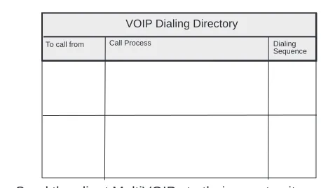
1. Establish your VOIP Dialing Directory based on your Phone Directory Database for the numbers to connect the MultiVOIPs to your VOIP network and the telephone extension number you need to connect the Voice/Fax channels. A sample VOIP Dialing Directory is provided below for your consideration and use.
To call from Call Process Dialing
Sequence
VOIP Dialing Directory
2. Send the client MultiVOIPs to their remote sites.
Remote Site Administrator 3. Unpack your MultiVOIP.
4. Connect one end of the power supply to a live AC outlet and connect the other end to the Power connection on your MultiVOIP.
FXS E&M
FXO
PSTN
Ethernet Connection Power Connection
10BASET
ETHERNET POWER Voice/Fax Channel
Connections
E&M FXO FXS
If you are connecting the station side of a telephone switch (PBX) to your MultiVOIP, connect one end of an RJ11 phone cord to the Voice/Fax Channel 1 FXO connector on the back of the MultiVOIP and the other end to the phone jack.
If you are connecting an E&M trunk from a telephone switch to your MultiVOIP, connect one end of an RJ45 phone cord to the Voice/Fax Channel 1 E&M connector on the back of the MultiVOIP and the other end to the trunk. Refer to Appendix B for E&M cabling pinout.
7. Repeat the above step to connect the remaining telephone equipment to each Voice/Fax Channel on your MultiVOIP.
8. Turn on power to the MultiVOIP by placing the ON/OFF switch on the back panel to the ON position. Wait for the BOOT LED on the MultiVOIP to go off before proceeding. This may take a couple of minutes to go off.
Introduction
This chapter describes the MultiVOIP software to show you how to make changes to the
configuration of your MultiVOIP. The major configuration parameters were established during the loading of the software (Chapter 3), and the MultiVOIP software and configuration utilities allow you to make changes to that initial configuration.
The MultiVOIP software allows you to refine your configuration based on your network connections. The software is based on a main menu (MultiVOIP Configuration) that allows you to consider all the parameters for a particular feature (for example, voice channels and phone book). These features, along with others are discussed in detail in the MultiVOIP Configuration section later in this chapter.
The other seven configuration utilities in the MultiVOIP 800 software provide additional functionality. The Configuration port setup utility enables you to change the method by which you access the MultiVOIP (through a direct connection of a PC to the Command Port on the MultiVOIP, or via your Internet or LAN connection to the LAN port on the MultiVOIP). The Date and Time setup utility enables you to easily set the date and time used for data logging in the MultiVOIP. Download Factory Defaults enables you to return the configuration to the original factory settings. Download Firmware enables you to download new versions of firmware as enhancements become available. Download User Defaults enables you to repeat the download factory defaults process (part of software installation) and update the MultiVOIP configuration with any necessary changes. Download Voice Coders enables you to download voice coders to the MultiVOIP after repair or upgrade. The Uninstall MultiVOIP Configuration utility removes most of the MultiVOIP 800 software from your PC. The UpGrade Software downloads boot code, factory defaults, firmware and voice coders in an automated process.
Before You Begin
MultiVOIP Configuration
The MultiVOIP Setup menu consists of 10 buttons in which you can point and click, an Events window in the middle of the menu, and a status bar at the bottom of the menu. The 10 buttons allow you to display and change the voice channels and IP protocol parameters, display and manage the Phone Book listing, define the output of the MultiVOIP, view statistics and call progress, and change features such as SNMP Agent, Telnet Server, WEB Server, and assign a MultiVOIP password.
The Events window, in the center of the window provides information about the boot process.
Changing Channel Parameters
The channel parameters include the interface type and its options, voice and fax settings, billing and security options, and voice communications for the region of the world that the MultiVOIP resides in. The Channel Setup dialog box is accessed from the Main menu.
Interface Tab
The Interface tab defines the parameters related to the physical interface of the voice/fax channel. Depending on the interface type selected (FXS, FXO, or E&M), other options on the Interface tab will become inactive indicating that they do not apply to the selected interface. Max Dial Digits, Inter Digit Time, and Autocall features apply to all interface types.
The Max Dial Digits indicates the maximum number of digits you can enter when dialing one of the numbers in the Phone Directory Database. As soon as you have entered this number of digits, the MultiVOIP will immediately attempt to match the digits you have dialed with an entry in the database. The range for the Max Dial Digits is from zero to 16 digits with a default of five.
The Inter Digit Time (in milliseconds) option in the Dialing Options group defines the amount of time the MultiVOIP waits between digits as they are entered by the user. If this timer expires, the
MultiVOIP will immediately attempt to match the digits entered to an entry in the Phone Directory Database. The range for this option is 200 to 10,000 with a default of 2,000.
The Auto Call option enables the local MultiVOIP to call a remote MultiVOIP without requiring the user to dial a Phone Directory Database number. As soon as you access the local MultiVOIP voice/ fax channel, the MultiVOIP immediately connects to the remote MultiVOIP that you identified in the Phone Number box of this option.
the dialed digits to an entry in the Phone Directory Database. If too much time elapses between digits, the wrong number maybe mapped, you may hear a rapid busy signal. If this happens, hang up and dial again. This option is available for all interface types. In the Flash Timer box, enter the time, in milliseconds, for the duration of flash hook signals output on the FXO or FXS interface.
FXO Interface
The FXO Interface is used to connect PBX extensions or central office telephone lines. You also, need to select DTMF or Pulse dialing in the Regeneration box of the Dialing Options group. If you are unsure of the correct selection, contact the personnel in charge of your PBX or your local
telephone company to determine whether pulse or DTMF should be used.
E&M Interface
The E&M Interface is used to connect PBX E&M trunks. You will need to select between Dial Tone or Wink signaling and also between 2-wire and 4-wire mode. If wink signaling is selected, the wink timer box becomes active with a range from 100 to 350 milliseconds. Contact the personnel in charge of your PBX to determine the proper configuration of these settings. If the Pass Through check box is selected, a continously open E&M voice path is established between two channels to pass voice packets. Available if the Dial Tone option is selected and auto-dialing is set up for the two channels that will be doing pass-through. This is useful for Public Address systems.
FXO Disconnect On
The FXO Disconnect On option applies when two MultiVOIPs are used in an FXO-to-FXO
configuration. When you have an FXO-to-FXO configuration, you need to determine the method of terminating the call. Three methods of terminating the call are provided: Current Loss, Tone Detection, or Silence Detection. Current Loss is the preferred method. Current Loss has to be supported by your PBX or local telephone company. Current Loss terminates the call when the PBX or local telephone company switch detects a person hanging up the phone and opens the local circuit for a minimum of 600 milliseconds.
Tone Detection disconnect method terminates the call when the party who wishes to disconnect enters a one or two digit sequence on the telephone keypad. Valid digits are zero to nine, *, #, and A thru D.
Silence Detection can be silence in one direction or silence in both directions for a specified amount of time. The amount of time is defined by the entry in the Silence Timer. The range of the Timer is from one to 65535 seconds (roughly 18 hours). The default is 15 seconds.
Voice/Fax Tab
The Voice/Fax tab controls the voice coder, Fax settings, DTMF gain, and some miscellaneous options.
The MultiVOIP supports many state-of-the art ITU (International Telecommunications Union) voice coders. The Voice Coder list enables you to select from a range of coders with specific bandwidths. The higher the bps rate, the more bandwidth is used. The channel that you are calling has to have the same voice coder selected. Otherwise, you will always get a Busy signal.
The Fax group enables a fax machine to transmit and receive faxes through the MultiVOIP. If a fax machine is connected to one of the voice/fax channels, the Max Baud Rate should be set to match the baud rate of the fax machine. Refer to user documentation for the fax machine. The Fax Volume setting controls the output level of the fax tones, and this setting should be changed only under the direction of Multi-Tech’s Technical Support personnel. See Chapter 6 - Warranty, Service
and Tech Support.
The DTMF Gain group controls the volume level of the digital tones sent out for Touchtone dialing. The Gain High and Gain Low boxes control the gain in dB (decibels) of the High and Low tones in the tone pairs; the default gain values are -4 dB and -7 dB, respectively. DTMF Gain should not be changed except under supervision of Multi-Tech’s Technical Support.
You can enable the voice/fax miscellaneous features by selecting the Silence Compression, Echo Cancellation, or Forward Error Correction check boxes.
the voice channel.
Billing/Security Options can be used to track the cost of Inbound and/or Outbound calls on any of the three interfaces (FXO, FXS, or E&M). The amount to be charged in cents is entered in the Charge ( ) Cents box together with the associated time duration in the Per ( )Seconds box. While a given call is active, the accumulated charges can then be viewed on the Call Progress dialog box. When the call ends, the charges are transferred to a Log File that can be viewed by highlighting the call event in the Log Entries dialog box and selecting Details.
The Call Authentication Option enables you to provide Password Protection on Inbound and Outbound calls on any of the three interfaces (FXO, FXS, and E&M). A password of up to 14 numeric characters can be assigned to either or both voice/fax channels. The required password must then be entered from the device initiating a call over the protected voice/fax channel.
Regional Tab
The Regional tab controls the voice communications for the country or region in which the MultiVOIP is being used.
From the Country/Region list, you can select the country or region for which you are configuring the MultiVOIP. The Tone Pairs group always displays the tones used in the country or region currently selected. In addition to Australia, Central America, Chile, Europe, France, Japan, UK, and USA, there is a Custom selection (with defaults identical to USA) that will make the Custom button active. Clicking Custom enables you to edit the Tone Pairs and establish custom sets of tone pairs for Dial Tone, Ring, and Busy.
Changing the Phone Directory Database
The Phone Directory Database dialog box displays all the phone numbers in your MultiVOIP network. The database displays the phone numbers in numerical order with the IP Address, Channel
assignment, and Description.
Access this database by clicking Phone Book on the MultiVOIP Main menu. You can add, delete, or edit any entry in the database and you can change the host-client relationship of the database. Click Client Status to display the status of all the client units in your VOIP network. The Phone Number of each client displays with its IP Address, current line status, and the description of the phone number.
client MultiVOIP will be defined as using dynamic addressing and the IP Address box will be unavailable.
If a Proxy Server with a static IP address is in front of the client MultiVOIP, then the IP Address box must contain the address of the Proxy Server.
If the client MultiVOIP is connected directly to the Internet, then its addressing mode must be Static. If the client unit is using Static addressing, then the IP Address box has to contain the Static IP address of the client MultiVOIP.
The Ethernet Node ID is a 12-digit Identification Number assigned to each unit. This Ethernet Node ID number is a hardware identification number that is affixed to each unit during the manufacturing process and cannot be changed. This ID number (for example, 0008005xxxxx) is located on an ID plate attached to every unit. This ID number has to be entered in the Ethernet Node ID box for the telephone number entered in the Phone Number box. If you are assigning a Phone Number for a client unit, the Ethernet Node ID has to be for that client unit.
If this plate is damaged or missing, you can also obtain the ID number by Telneting to the unit. From the MultiVOIP Telnet Server menu, choose the Voice over IP Configuration option which takes you to the Main menu. In the Main menu, choose System Information and the ID number is presented in the Ethernet Port Address of the System Information menu.
When you enter this information and click OK, the information is loaded into the phone directory database.
To add a second entry, click Add and the Add/Edit Phone Entry dialog box displays again. The same data needs to be added for each channel. After the two local entries are added to the database, then you need to turn your attention to the entries for the remote MultiVOIPs. The same data has to be added for each remote MultiVOIP.
Changing IP Parameters
The IP Setup dialog box establishes the IP addressing for the local Ethernet LAN, defines the Internet gateway address, and if a proxy server is used to connect a LAN to the Internet, global-to-local IP address translation is required. The IP Setup dialog box is accessed from the Main MultiVOIP menu by clicking IP.
When the IP Setup dialog box displays, the IP address of your LAN displays with its IP Mask. The Gateway Address is the IP address of the device connected to the line that is connected to the Internet.
Proxy Setup
MultiVOIP located behind a Proxy Server at the static IP address. This static IP address will be used in the Phone Directory Database when assigning directory numbers to this MultiVOIP.
Viewing Statistics
The Statistics dialog box enables you to view statistics for major events of the MultiVOIP operation. This dialog box is accessed by clicking on the Statistics button on the Main MultiVOIP menu.
Statistics can be a helpful troubleshooting tool. For example, viewing the Voice Channel statistics you can see the attempted and completed calls, call duration, average call length, bytes/packets send and received, and so on.
IP Statistics
For the most part these statistics are informational, and their use as a troubleshooting tool will be contingent on the applications running in the upper layers. For example, if you were having problems connecting to the MultiVOIP’s web server, you would look under the TCP section to see if any
connections are being established. If not, that may indicate the web server is not enabled. Or, if you were having problems establishing a remote connection through TFTP, you could look in the UDP section to see if any packets are being received. If not, you may need to review your network addressing.
SNMP Statistics
The SNMP Statistics dialog box provides statistical information on Simple Network Management Protocol (SNMP).
SNMP is an application layer protocol that facilitates the exchange of management information between network devices. There are three key components in SNMP: the devices that are to be managed, agents, and the network management systems. The managed device is the network device, like a router. The agent is the software module residing in the managed device pertaining to network management. The network management system runs the SNMP application that controls the managed devices and monitors their status. Four primary operations--Set, Get, Get Next, and Trap--are performed using SNMP.
Others Setup
Clicking Others on the Main menu displays the Others Setup dialog box. This dialog box lets you to enable SNMP Agent (the default is disabled) and set up all the necessary parameters; enable or disable various remote configuration methods such as TFTP (Trivial File Transfer Protocol) Server, Web Server, Dumb Terminal, and Telnet Server; and assign a Password to the MultiVOIP for Internet security. These applications enable remote viewing and changing of the MultiVOIP configuration, or updating firmware, from anywhere on the connected internetwork.
Verify that the desired applications are enabled (checked). The default condition is all applications are checked. To disable a given application, click to uncheck the check box and disable support.
SNMP related operations can be performed only when the SNMP Agent is enabled (checked) on this dialog box. The IP address of the system (SNMP Manager) that will receive the Traps from the MultiVOIP should be entered in the IP Address box in the Trap Manager group. The Community Name of the SNMP Manager receiving the Traps can be a maximum of 19 characters and is case sensitive. The default Port Number of the SNMP Manager receiving the Traps is 162. The MultiVOIP currently supports a maximum of two community users at a time, and they can be assigned either Read/Write or Read Only rights.
Viewing Call Progress
The Call Progress dialog box displays the status of a call in progress. This dialog box is accessed from the MultiVOIP Setup menu by clicking Call Progress.
The ratio of Packets Lost versus Packets Received provides a general indication of the integrity of the Internet connection. To reduce the frequency of lost packets, select a low-bit-rate coder, such as G.723 or Netcoder. Selecting the Forward Error Correction check box on the Voice/Fax tab in the Channel Setup dialog box enables the MultiVOIP to recover many of the lost packets.
Viewing Logs
The Log Entries dialog box displays a chronological history of all calls into and out of this unit. Click Logs in the Statistics dialog box to open this dialog box.
The Log Entries dialog box displays each call as a sequentially numbered Event with the date, time, duration of the call, the status of the call (Successful or Unsuccessful), Mode (Voice or Fax), and the from and to numbers.
Viewing Log Entry Details
Reports
Introduction
This chapter provides procedures for viewing or changing the configuration of a remote unit. Two methods are provided to access a remote unit. The first method is modem based and the second method is using IP. Within the IP method, three applications can be used: 1) LAN-Based using TFTP (Trivial lFile Transfer Protocol), 2)Telnet as a client application, or 3) a standard web browser on the Internet.
Remote Configuration
Remote configuration requires the MultiVOIP software to be loaded on the local PC. The local PC then controls the remote MultiVOIP either via the modem connection or the LAN.
Modem-Based
To remotely configure a MultiVOIP, a local PC needs to be connected to a dial-up line and the MultiVOIP software configured to call the remote MultiVOIP. The remote MultiVOIP needs to have a modem connected to a dial-up line and the Command Port. Once the connection to the remote unit is made, you can change the configuration as you see fit. Once the configuration is changed, you can down load the new configuration to the remote MultiVOIP. Refer to the Modem-Based Remote Configuration Procedure in this chapter to remotely configure a MultiVOIP.
1. At the remote site, remove the serial cable from the PC to the Command Port connector on the back panel of the MultiVOIP.
2. At the remote site, connect a special cable (Remote Configuration Cable) from the Command Port connector on the back panel of the MultiVOIP to the RS-232 connector on the modem. The special cable is a serial cable with male connectors on both ends. Refer to Appendix B for cable details.
Connect the modem to your local telephone line.
Provide your telephone number to the person verifying your configuration.
Configure the remote modem for 19200 baud and turn on Force DTR.
3. At the main site, connect your local PC to a modem that is connected to a dial-up line.
4. Install the MultiVOIP software on the local PC. When installed, click Start | Programs | MultiVOIP | Configuration Port Setup, or double-click on the Configuration Port icon in the MultiVOIP program group.