486 IJSTR©2020
Lightning Return Stroke Models – A Critical
Review Based On Comparison Of Lightning
Parameters
Srisailam Sreedhar, Venkatesh Srinivasan
Abstract: Lightning is an intense bright discharge of the ionized sky or a thin channel of luminous spark directed towards the earth through the air that could present considerable risk to mankind and also possibly cause significant damage to buildings, monuments, transmission lines etc. Hence, it is necessary to provide appropriate protection against such large currents and strong electromagnetic radiation that are created from lightning phenomenon. A domain of considerable significance that continues to present considerable challenges to the scientific fraternity in the field of lightning protection is in understanding the underlying physical development process of lightning and the consequent disaster mechanism. Researchers have carried out diverse experimental analysis to ascertain the role and characteristics of lightning which occurs due to discharg e of the large amount of charge accumulated in the cloud. Lightning discharge occurring between the nearest clouds called Cloud-to-Cloud (CC) flash or discharges which travel as a stepped leader which reaches earth forming Cloud-to-Ground (CG) flash are of significant interest. The hazards caused by the lightning are invariably modelled and inferred as a consequence of the resulting return stroke formed during the process of stepped leader descending on to the earth or a grounded system. In this context, several researchers have developed and postulated models by representing prop erties of lightning return stroke utilizing experimental data such as time-based changes in the base current and its derivatives, return stroke speed and electromagnetic field etc to a substantial degree of success. Though return models based to gas dynamics, electromagnetics, transmission line, hybrid and leader attachment representations has been widely utilized by the scientific community recently, there has been renewed focus in understanding and implementing modelling of lightning return strokes based on hybrid models and representation based on leader attachment methods. This research study focuses on providing a comprehensive overview and detailed comparison of various categories in lightning return stroke models, in addition to appropriate assumptions, merits and limitations to facilitate better understanding on characteristics of lightning phenomenon and provide vital clues into implementation of return stroke modelling.
Index Terms: Distributed Circuit Models, Electro-Magnetic Models, Engineering Models, Gas Dynamic Models, Lightning Attachment Models, Return stroke, Stepped leader.
—————————— ——————————
1.
INTROLDUCTION
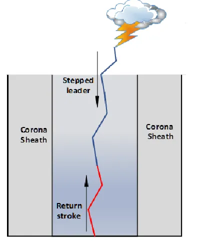
Lightning is an unpredictable natural phenomenon that discharges static electricity from charged regions of clouds and poses considerable perils for not only structures but also to human and live-stokes. The most commonly occurring lightning flashes during the time of thunderstorm are Cloud-to- Cloud (CC) and Cloud-to-Ground (CG) flashes [1]. The latter, can cause severe damages to structures related to power transmission and distribution, edifices of critical care, historical monuments of archaeological importance, fauna, forests etc. During the process of CG flash, a stepped leader is initiated which in turn propagates and travels through the air by ionizing it whereby releasing substantial quantum of charge from the cloud to likely closest tall object or ground. Due to the enormous charge of the central core of the stepped leader, branches are invariably produced to discharge around the
core forming a corona sheath [2]. In turn, during this process, a steamer is produced from the earthed object called as connecting leader with the opposite polarity of the stepped leader. During the energy conservation process of the contact of upward streamer with that of the downward pilot leader, an interchange of charge occurs. No sooner than the charge transfers to the ground, that an abrupt and a quick shock wave with very high luminosity is created which accelerates towards the charged cloud either along the same ionized path created by the stepped leader or through an alternate path. This process is called as a return stroke. In a few distinct cases, return strokes can also initiate another leader called as the dart leader, which follows the same path of previous stepped leader to hit the ground. This process may continue to occur for a few times until the charged cloud gets neutralized.
————————————————
Srisailam Sreedhar is currently pursuing Ph.D. degree program in School of Electrical Engineering in Vellore Institute of Technology, India. E-mail: [email protected]
487
Researchers have carried out rigorous studies to evaluate and ascertain the stepped leader charge distribution in order to analyse and understand the properties of lightning. Such studies include estimation of the distribution of charges by utilizing inversion electric field measurements [3] along the stepped leader near ground point whereby the models are developed for estimating the amount of charge that have been assumed to be distributed uniformly along the lightning channel. Such models usually compute the charge along the channel by assuming that the stepped leader is devoid of branches (neglecting the charge contribution to the return stroke by the branched channels). It is worth noting that this would imply over-estimation of the charge along the channel since a few regions of the charge are located and distributed through branches, which may in turn affect the electric field calculation near the ground point. In order to avoid the incorrect computation of the charge distribution along the lightning channel, studies have been taken up by researchers during the past few decades to characterize the properties of lightning return strokes by developing return stroke models using experimental data. In this context, it is pertinent to note that a few major parameters invariably considered for developing mathematical models representing return stroke includes current of the return stroke, electric field and magnetic field [4]. As the electric and magnetic field values of lightning are quite complex and extremely difficult to calculate at very close distances, usually approximate values are considered during the computation process. It is therefore evident from the preceding discussion that a thorough survey and a comprehensive study is imperative in order to provide a clear understanding and focus on aspects that discriminate the unique categories of return stroke models based on lightning physics, laboratory experiments and numerical simulations. Various models developed by several researchers are also discussed along with appropriate underlying assumptions, essential inputs and unique outcomes of each model.
2
RETURN
STROKE
MODELS
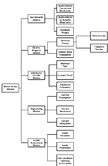
Lightning hazards are usually due to the formation of return stroke during the process of stepped leader coming into contact with an upward streamer from the tall object or the ground. During this process, the return stroke will travel either along the ionized path created by the stepped leader or with an alternative path, in turn reaching the cloud to neutralize the enormous accumulated charge [5]. In this context, researchers have developed various lightning stepped leader models and return stroke models to attempt provide a comprehensive understanding of lightning phenomenon and its associated physics. Studies clearly indicate that in stepped leader models, the total amount of charge distribution along the channel invariably cannot be estimated [6]. Further, studies carried out by several researchers with various assumptions that represent divergent return stroke models also indicate that development of models pertaining to return strokes models [7 - 10] have also been introduced to compute the amount of charge being distributed along the channel to understand the properties of natural lightning. The models are mainly categorized as a) Gas Dynamic Models, b) Electromagnetic Models, c) Transmission Line Models, d) Engineering Models and e) Leader Attachment Models. Fig. 1 succinctly summarizes the concepts of various return stroke models developed by researchers, hitherto.
Fig. 1 Types of Return Stroke Models
2.1 Gas Dynamic Models
[8-488 IJSTR©2020
10] wherein laws of conservation of mass, momentum and energy are implemented.
The governing equations that form a part of modelling include:
Conservation of mass: =
(1)
Conservation of momentum:
= −𝑟 (𝑃 + 𝑄) (2)
Conservation of energy:
+ 𝑃
+ 𝑄
+
+ 𝐷 = 0 (3)
where m is the particle mass per unit length of channel given by 𝑚 = ∫ 𝜌𝑟 𝑑𝑟, ρ is the mass of air per unit volume in kg/m3, V is the volume in m3/kg, r refers to radial distance in m, u refers
to
Fig. 2 Phenomena of Gas Dynamics Model
the velocity of the particle in m/s, t represents time, P refers to the pressure in J/m3, Q refers to viscosity pressure in kg/m, E refers to specific internal energy in J/kg, D represents the rate of specific energy source in J/kg and L represents luminosity in J/s.In addition to the three-governing equation, a few other major equations that have also been proposed by researchers for modelling return strokes are based on:
Thermal state equation given by
𝑃 = 𝜌𝑅𝑇 (4)
Caloric state equation: 𝐸 =
( ) (5)
where R represents per unit mass gas constant, T represents temperature and 𝛾 represents the specific heat ratio which is constant. In the context of various gas dynamic models, several researchers have proposed a wide variety of models which include aspects related to computing the value of the radial spark channel current and shock (pressure) wave as a function of electric field and time [11-14] as a factor dependent on radius, pressure and temperature. Further, models of spark channel in terms of acoustic wave [15-18], [19] envisages obtaining the time dependent temperature profile of air channel heated by the lightning stroke. Another model variant indicated in [20], estimates the dissipation of energy of channel. It is pertinent to note that the gas dynamic models have a few specific limitations [21] namely: 1. precludes the use of longitudinal evolution of lightning channel; 2. excludes
the effects of electromagnetic skin effect and 3. ignores aspects related to corona sheath (though it contains maximum charge) of the stepped leader. Table 1 gives a comprehensive recap of the return models postulated by several authors along with appropriate underlying assumptions.
TABLE1
GAS DYNAMIC MODELS
Model Parameters/characteristics related to the evolution of the model
Interpretation of observation by researchers Drabkina [11] Radial spark channel has
been used
Assumptions:
o Spark channel pressure > development of spark channel radially o Shockwave as a function
= 𝑓[(𝐸(𝑡)]
The pressure in spark channel is observed to drop to 10 Atm in less than 5 μs Braginskii
[12] oAssumptions: Spark channel (radius, pressure, temperature) = 𝑓[𝐼(𝑡)]
o Conductivity of channel = 2.22 × 10 𝑆/𝑚 o Air density (ρ) = 1.29 ×
10 𝑔/𝑎𝑚 Model Outputs:
o 𝐼(𝑡) =
𝑟(𝑡) ≈ 9.35[𝐼(𝑡) / 𝑡 / ]
Where r(t) represents the radius in centimetres, t represents time seconds, I(t) in amperes
o Energy/ length is 𝑊(𝑡) = ∫ 𝐼(𝜏)𝑅(𝜏) 𝑑𝜏
Electrical conductivity and thermal conductivity of the ionized gas in the channel are utilized to compute the state of gas
Hill [13, 14] Assumptions:
o Temperature profiles are flat
o Channel is optically thin to spectroscopic lines
Inputs: o Experimental
information/details on electrical currents o Heating source function,
conductivity, opacity function, initial conditions
Model output:
o Temperature profile with respect to time o Radial Temperature and
time, the Temperature profile of air channel heated by a stroke
Temperatures at the edge of the channel are lower than on the axis
Experimental estimate of energy 107 to
3.3 × 10¹¹
ergs/cm
Theoretical value calculated = 1.5 × 10⁹
ergs/cm (lower)
Krider [15] Approximations: o Radiant power varies
linearly with respect to the output power obtained from the sources within the bandwidth of the detector
o Radiative efficiency is observed to be equal at maximum power
Model outputs: o Total radiant energy
within a spectral region 𝑃 = ( )(
) Where V represents output
Average power input/length of 7.8 ×
10 𝑊/𝑚
489 voltage of the detector, k
represents calibration factor, R refers the ga between source and detector, A represents sensitive area of the detector
Plooster
[16]-[18] oInitial conditions: Temperature, Radius, Pressure and current waveform
Model outputs:
o Discharge channel radii o Energy dissipated/ length
Temperature vs time curves are found consistent regarding model validation studies Minor influence on the prediction of spark channel parameters Borovsky
[19] Lightning channel growth as energy flow model: o Electrostatic energy is
delivered to the channel by a leader
o The return stroke dissipated this locally stored energy o Calculation of energy
dissipated/ length o Energy conservation to
calculate the radii of the lightning channel o Initial and final radii
expansion
o Estimating radial velocity of energy flow
Energy dissipation/ length vary from 2 × 10² J/m to 1 × 10⁴ J/m
Initial and final channel radii o rinitial: 0.08
cm to 1.5cm o rfinal: 1.2
cm to 20cm
Heating values of rise time vary from 1 μs to 200 μs Paxton [20] Similar to Plooster model,
multi-group treatment of radiator transport to obtain an optical output
Development of estimation of the electric current waveform from the optical emission of the return stroke
Assumptions:
o Lightning channel is axially symmetric, and calculation is one dimensional
Lightning channel model hydrodynamic treatment: o Initial temperature
distribution:
𝑇(𝑟) = 𝑇 + 𝑇
(1 +𝑟 𝛼 ) Where α0 refers to the initial
channel of hot gas
Radiative Transport: o Radiative transfer
𝐼 ≡ (𝜕 𝜕𝑡+ 𝑐𝛼𝛻)𝐼 o Sinks = 𝑐(𝑘 + 𝑘 )𝐼
Where kabs is frequency
and temperature absorption coefficient, kscat
loss of intensity due to
Involves boundary condition that transmits shock wave to have adequate resolution
Incorporates a lookup table of temperature and frequency dependent opacities
Uses diffusion approximation to treat the transport
scattering from one frequency to other frequency
o Sources =
𝑐𝑘 𝐵(𝑡, 𝑣) + 𝑆
o 𝐵(𝑡, 𝑣) = Spectral temperature of
gas: 𝐼 𝐼 =𝑔𝐴 𝑣 𝑒 / 𝑔𝐴 𝑣 𝑒 /
Where gi refers to
degeneracy of state i, Ei is
the energy of state i, Aij is
the Einstein coefficient Dabuvoy [21] Electric field impulses and
radar echo measurement for numerical modelling
Model output:
o current in return stroke
Amount of energy acquired in the channel:
𝐼(𝑡)
= 𝐼
{
0 𝑡 ≤ 0 𝑡
𝑡 + 𝐼 0 ≤ 𝑡 ≤ 𝑡
𝑒[
( ) ]
+ 𝐼 𝑡 ≤ 𝑡 Where I0 = 10, … 110 kA,
allowed variation of maximum current in the lightning channel Ic, tm = 1,
… 15 μs represents typical current rising time, tc = 20,
… 100 μs represents current decreasing time
Reflection of radio wave created from the ionized path of the lightning channel:
o Reflecting surface (S) = 𝑙𝑅|𝑉| , l is the channel length, |𝑉| is power reflection coefficient o If R << λ i.e., 2ΠR << λ
λ is the radar wavelength
o 𝑆 =
𝛱𝜆𝑙 | |
.
Limitations of Hill and Plooster model are eliminated in this model by considering energy transport by radiation with 10 spectrum groups
Measured and computed results agree in the relative height of maximum width44 and minimum depth Continuous current varies from 2 A to 10 A
The energy released in return stroke is ≈ 1 KJ/m
2.2 Electromagnetic Models
490 IJSTR©2020
Incidentally, several researchers [22-26] have developed techniques based on electromagnetic models using Antenna Theory. A simple monopole antenna model is represented in Fig. 3, wherein the lightning return stroke is considered as lossy antenna. A few other researchers [27] have modified the process of dart leader and return stroke as a guided wave propagation discharge along the conducting cylindrical channel. In this model [27], the dart leader and the upward streamer are considered as a single dominant sinusoid, wherein the estimation of current distribution along the channel is not estimated. However, the central core of the lightning channel alone is considered since it is undistorted by the conditions at the channel end. Table 2 provides a brief review of a few significant electromagnetic models along with specific observations indicated by researchers.
Fig. 3. Monopole representation of Antenna Model
Researchers have utilized Chen's analytical equations [28] to compute the current travelling through a wire perpendicular to the ground and excited by a lumped source. Studies [28] utilizing such models have unequivocally indicated that the current dispersion is being satisfied by the limitations of the electric field lying on the exterior of vertical wire and are being discussed in the following subsections
TABLE2
ELECTROMAGNETIC MODELS
Model Parameters/characteristics related to the evolution of the model
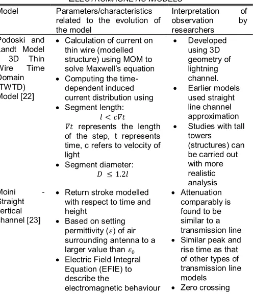
Interpretation of observation by researchers Podoski and
Landt Model - 3D Thin Wire Time Domain (TWTD) Model [22]
Calculation of current on thin wire (modelled structure) using MOM to solve Maxwell‘s equation
Computing the time-dependent induced current distribution using
Segment length: 𝑙 < 𝑐𝛻𝑡
𝛻𝑡 represents the length of the step, t represents time, c refers to velocity of light
Segment diameter: 𝐷 ≤ 1.2𝑙
Developed using 3D geometry of lightning channel.
Earlier models used straight line channel approximation
Studies with tall towers (structures) can be carried out with more realistic analysis Moini -
Straight vertical channel [23]
Return stroke modelled with respect to time and height
Based on setting permittivity (𝜀) of air surrounding antenna to a larger value than 𝜀
Electric Field Integral Equation (EFIE) to describe the
electromagnetic behaviour
Attenuation comparably is found to be similar to a transmission line
Similar peak and rise time as that of other types of transmission line models
Zero crossing
of the antenna
MOM for EFIE solution in the time domain to provide space-time distribution of current
Adjustable parameters: o Return stroke
Progression speed o Channel
resistance/length
does not occur within the first 100μs
Borovsky - Guided wave propagation [27]
Cylindrical Channel is assumed
Wave mode propagation fields are harmonic and of form 𝑒
Guided wave modelled as a function of:
o Channel radius (rch)
o Channel temperature (T)
o Rise time (𝛻𝑡) o Poynting flux along
and into the channel as energy
Size of channel radius and skin depth plays a vital role
Electric fields are predominantly electro-static inside and outside the channel
2.2.1 Mathematical representation of conductor placed perpendicular to the ground based on its current distribution
A Using Chen‘s analytical equation, the transient current of an infinite long conducting cylinder in air comprises a cylinder which is excited in the core by a step voltage generating source and is given by
𝐼(𝑧, 𝑡) = 𝑡𝑎𝑛 (
(√ )
) (6)
where η refers to free space impedance and a represents the radius of cylinder, c represents the speed of light, z refers to the impedance and V refers to the step voltage. Computing Eq. 6 for a vertical wire at variable heights, ramp wave front is being produced and the current wave attenuates as it propagates along the wire. This Eq. 6 is used to test the precision of the techniques related to electromagnetic return stroke models.
2.2.2 Attenuation of Current Wave with No Losses
Researchers in [25] have analysed the methodology of weakening of the current pulse travelling through perpendicular wire by lengthening the tail to transfer the transmission of charges irrespective of the height. It is observed that the electromagnetic field tends to be more definite and depends on a) the width of vertical wire, b) altitude of the source, c) frequency and d) the altitude above the excitation point. In this context, the current attenuation is required to satisfy the limiting condition of the electric field of the perpendicular wire.
2.2.3 Types of Return Stroke Model Representations
Several models have been conceptualized, developed and analysed as reported in studies indicated in [29]. Such models include the following variants:
a. Vertical resistive wire above the ground
b. Vertical wire above the ground with series inductance distributed along the line
c. Vertical wire enclosed by a dielectric medium placed on top of the conducting ground
491
e. Coated with a dielectric material with high relative permittivity and permeability on a vertical wire above the ground
f. Two parallel wires connected with distributed shunt capacitances between them
2.2.3.1 Vertical resistive wire above the ground
In this representation, as detailed in studies carried out in [22], Thin Wire Time Domain (TWTD) model has been utilized to represent a direct lightning strike to the Canadian National (CN) Tower in Toronto by a wire with non-linear resistor connected from the bottom of the resistive wire to the top of the CN tower. It is evident from the analysis and inferences of such studies that as the propagation of the current wave along the wire has been construed to be equivalent to the speed of light and upward streamer is computed nearly 2 to 3 times more than the actual return stroke wave-front speed, leading to overestimation of remote electric and magnetic fields.
2.2.3.2 Vertical wire above the ground with series inductance distributed along the line
This model has utilized theory of Transverse Electro-Magnetic (TEM) wave-based R-L-C transmission line theory, wherein the return stroke is characterized as a perpendicular straight wire above the ground with a series of distributed inductances along the line. These series inductances and shunt capacitances vary with the height, whereby giving a non-TEM electromagnetic field structure.
2.2.3.3 Vertical wire enclosed by a dielectric medium placed on top of the conducting ground
This model utilizes estimation of R-L-C in a transmission line to analyse the current wave propagation velocity and impedance characteristics along the perpendicular wire to the ground whereby the air above the ground is presumed to be replaced with dielectric medium with a relative permittivity 𝜀. With this modification, the distribution of current along the line can be computed and the medium is replaced back with air while calculating the electromagnetic fields in air.
2.2.3.4 Coated dielectric material on a vertical wire above the ground
This model represents the lightning channel as a perpendicular wire with respect to a ground vertical placed in an axis which is similar to that of the dielectric cylinder with a finite relative permittivity. The travelling speed of current wave is considered to be approximated to be 0.7c where c represents speed of light. This methodology in turn has been utilized to compute the current distribution of the wire and to estimate far electromagnetic fields.
2.2.3.5 Coated with a dielectric material with high relative permittivity and permeability on a vertical wire above the ground
In this model, the lightning channel is represented by a vertical wire positioned along the axis of a cylinder or parallel pipe-shaped block with high relative permittivity and permeability. The travelling speed of the current wavefront is approximated to be 0.5c. This method also computes the distributed current along the line and also estimates the electromagnetic fields. However, this model represents and computes the characteristic impedance to be higher than the model related to vertical wire above the ground with plated dielectric material
since the relative permittivity and permeability are high.
2.2.3.6 Two parallel wires connected with distributed shunt capacitances between them
This method of representation is utilized to examine the phase velocity and impedance characteristics of a vertical wire equipped with shunt capacitance. The amount of current distributed throughout the line is computed by using two parallel wires by adding shunt capacitance between them, excited at the end terminal of the line by a lumped voltage source. This estimated measure of current distribution aids in approximating the electromagnetic fields. Some of the limitations of these models include: 1. Inability to consider arbitrary shape of 1-dimensional representation of leader; hence, model does not consider branches, nonlinear effects, striking object etc., 2. Does not deal with complexities related to modelling the corona layer around lightning channel, 3. Unsubstantiated validation of theoretical model for obtaining precise ratio of wire radius to skin depth and channel radius to channel depth with that of experimental simulation.
2.3 Distributed Circuits Models
Models that form a part of this category simulates the return-stroke channel as a vertical transmission line [4, 30] with specific values of series Inductance (L), Resistance (R) and shunt Capacitance (C) per unit length and computes voltage and current. In this context, the electromagnetic waves travelling along a transmission line is hypothesized to exhibit a quasi-TEM field structure. These models characterize the transmission line being charged initially by the previous stepped leader to a certain potential and gets terminated at the earthed end with a finite resistance which in turn initiates a return stroke. The parameters of the transmission line are functions of time and space; hence these representations are evidently non-linear and non-uniform. The non-linear variations of channel parameters are due to: 1. dissimilarities in the inductance of the channel due to the Z- coordinate directed component of current carried by its radius, 2. changes in the resistance due to the variations in the density of electrons and core radius of the channel and 3. modifications in the capacitance of the channel due to the counteraction of the corona sheath (evolving radially) which in turn surrounds the core of the channel and obviously comprises entire bulk of charge stored in the channel due to the preceding leader. There are three main categories of distributed circuit models that are derived by utilizing the transmission line theory, namely: 1. Discharge models [31-35], 2. Lumped excitation models [36-40] and 3. Parameter estimation models [41, 42]. The first category models consider representing the return stroke as a discharge of a charged transmission line whereas the second category models represent the return stroke as a transmission line excited by a lumped source. The models falling under the third category are used to estimate the parameters that help in estimating the lightning properties.
2.3.1 Discharge Models
492 IJSTR©2020
represent first and subsequent strokes does not specify the boundary conditions at the bottom of the channel. These models are being used to envisage the spatial and temporal current distribution of the upward streamer. But these currents usually decay in magnitude and increases in rising time with a consistent increase in channel height with return stroke luminosity profiles. It has been observed during studies that there have been considerable dissimilarities between estimated current parameters at the channel base and measured data due to the approximate prediction of electromagnetic fields which are usually inconsistent.
Fig. 4. Discharge type model representation
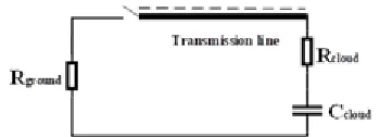
2.3.2 Lumped Excitation Models
The main concept of these models is with the premise that the lightning channel is considered as an uncharged transmission line, which is excited at one end by a lumped source as represented in Fig. 5, where R∆z is the line series resistance, L∆z is the line series impedance, C∆z is the shunt capacitance of the line and G∆z is the line shunt conductance. Therefore, the flow of current I at any instant z of the channel at any time t will be a delayed replica of the current I(0, t), which is injected at the channel base by a lumped current source. If a current source is used as a lumped source, the initial channel current is taken as an input for the model. If a voltage source is used as a lumped source, then the initial channel current becomes the result of the model. On the usage of voltage lumped source, it is obvious that the amount of voltage can be varied to obtain a desired base current waveform for a non-linear return stroke model. These models are used to predict the current and remote electromagnetic fields, which produces observable features of lightning.
Fig. 5. Lumped Excitation Model representation
2.3.3 Parameter Estimation Models
In these models, upward streamer current and transmission line current pulse are utilized to obtain the parameters that helps in analysing and estimation of lightning physical properties. Table 3 encapsulates an insight into various distributed circuits models with details on significant unique characteristics of each model.
TABLE3
DISTRIBUTED CIRCUITS MODELS
Model Unique features/ Characteristics of models Baum and Baker
[31] Transmission line model of leader stroke is used to develop a model for the return stroke
Steepening of the wave front and consequent development of jump discontinuity due to direct correlation of propagation velocity of
coronal charge and channel radius
Found the radius of the corona in order of meters.
Price and Pierce
[32] Lightning channel as a vertical transmission line
Included resistive losses along the line Little [33] The magnitude of current falls as the height
increases
More decay than the double exponential pulse Takagi and
Takeuti [34] Observed the changes in the electric field of lightning during thunderstorms in winter
Return stroke current is computed to find the field change due to the current at several distances
Quinn [35] Transmission line theory is utilized to model the current waveform of lightning
Marcos et al. [36] A nonlinear model developed by Braginskii is used with upper and lower limits
Discharge channel has received less attention in the overall study of the interaction
Improvements over the previous models are introduced for the cloud losses and channel resistance
Mattos and Christopoulus [37]
Incorporates resistance nonlinearities and effects of corona for a transmission line representation of lightning return stroke
The velocity of propagation decreases with height
Predicts current waveforms, channel velocity, impedance and radiated fields
Kostenko [38] Nonlinear electrodynamic characteristics of return stroke are estimated
Lightning impedance changes depending on the lightning current
Amoruso and
Lattarulo [39] Correlates ground level return stroke currents to surface electromagnetic fields
Modified transmission line model with nonlinear characteristic impedance is anticipated
Considers velocity of current propagation as a finite value
Channel current oscillations are neglected for factors which could include:
o Markedly attenuated discharge current at upper region of the channel which may be attributed to the propagation along a non-uniform line
o Effective counteraction takes places on the residual return stroke current which is attributed to pockets of opposite charges inside the cloud
Vasacro and De
Conti [40] The Dynamic Non-Uniform Transmission Line (DNUTL) is used to compute time and height dependence of the channel parameters
Lightning channel into three different zones: o Leader channel: Corona sheath, high
losses 0.33 < v < 0.66c
o Channel in transition: reducing corona sheath and losses and increasing v o Return stroke channel: no corona sheath,
reduced losses, v is approximately equal to c
Rakov [41] Modelled an R-L-C transmission line for dart leaders and return strokes propagation mechanisms are inferred
The transmission line is assumed to be linear (R = constant)
Dart leader is described as moving ionizing front generates current waves propagating upward
Oetzel [42] Two models: The Lumped Circuit Model and The Resonant Circuit Model with the charged transmission line
493 actual measured current at the base of
lightning strokes
Calculated electrical diameter of the return stroke from waveform measurements 2.4 Engineering Models
Engineering models have been postulated using substantial physical concepts though partially circumventing aspects of physics during the course of selecting the inputs required for modelling, as these input parameters are not evaluated by fundamental principles [6-8]. Such models describe the longitudinal lightning channel current at any height and at any period with that of the current at the channel origin. Though these models have been reviewed by several researchers, in all the cases considered thus far, the return stroke wave-front speed has been selected arbitrarily and used as one of the input parameters. The input parameters for engineering models are obtained from experimental data and some are taken from the model results fit the experimental data. These models consider the channel of lightning stepped leader as a transmission line and current propagation along the line as a return stroke which is considered to be grounded at one end. These models are further classified into three types by utilizing the concept of transmission line theory namely: current generation, propagation and dissipation models.
2.4.1 Current Propagation Models (CPM)
These models consider the upward streamer as a current pulse starting from the earth potential which propagates to the cloud along the path created by the stepped leader with no losses. This model invariably forms the basis for many researchers to evolve and construct different engineering models like Transmission line model (TL) [43-48], wherein the current is considered to travel as lossless parameter along the channel with a constant speed. In the case of Modified Transmission Line with Linear current decay model (MTLL) [49], it is pertinent to note that such models consider linear decrease in the current amplitude, while in Modified Transmission Line with Exponential current decay model (MTLE) [50, 51], it is assumed that the current amplitude decreases exponentially. Table 4 summarizes an insight into current propagation models with specific characteristics of each model.
TABLE4
DISTRIBUTED CIRCUITS MODELS
Model Unique features/ Characteristics of models Norinder‘s Model
[43]
Estimation of lightning currents by current pulses within the strikes and hence an average of 4 values of flash to compare with maximum value recorded
Described the current in the strokes using Norinder‘s distribution
Bruce and Golde
[44] Proposes the shape of lightning current wave in the return stroke
Expression for stroke mechanism related to shape and amplitude of current
Lundholm [45] Modelling return stroke in terms of speed and peak current
Postulates increase in peak current with speed
Dennis and Pierce
[46]
Return stroke modelled combining theoretical and experimental measurement of current surges
Obtaining mean amplitude spectra of current based on narrow and wideband and shape of
the amplitude spectrum
Plot of log-normal distribution of Ef1/Ef2 Vs
Amplitude (E) is obtained Uman and McLain
[47] Postulated return stroke based on magnetic field
Channel current varies with respect to time and channel altitude modelled for 1st and
subsequent strokes
Postulated magnetic field rise time in the channel base but for subsequent strokes influenced by current fall times
Cooray and Orville
[48] Modelled and estimated the impacts of change in o Current amplitude (peak current, rise time), return stroke and rate of change of speed at ground level)
o Effect of channel tortuosity Rakov and Dulzon
[49] Modelling modification based on height dependent of transmission line with attenuation factor for return stroke current pulse intensity
Studies on aspects related to early and late stages of return stroke process based on height dependent factor of attenuation Master et al. [50] Modelling based on revised transmission
line return stroke current
Current pulse breakdown depends on the height and decreases exponentially Rachidi and Nucci
[51] Obtained mathematical expression for distant fields and lightning channel base current
Carried out a detailed study based of Master, Uman, Lin, Standler (MULS) and Lin, Uman, Standler (LUS) models of Modified Transmission Line (MTL) to postulate mathematically a specific channel base current expression
2.4.2 Current Generation Models (CGM)
494 IJSTR©2020
the model describes about the positive charges due to the impact of background field and the time constant related to the corona current whereby facilitating the representation as a substantially meaningful channel current and speed prediction mechanism of the return stroke. Table 5 summarizes the significant observations and analysis of the research studies.
TABLE5
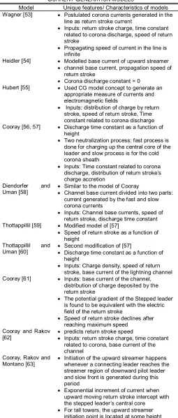
CURRENT GENERATION MODELS
Model Unique features/ Characteristics of models Wagner [53] Postulated corona currents generated in the
line as return stroke current
Inputs: return stroke charge, time constant related to corona discharge, speed of return stroke
Propagating speed of current in the line is infinite
Heidler [54] Modelled base current of upward streamer
channel base current, propagation speed of return stroke
Corona discharge constant = 0 Hubert [55] Used CG model concept to generate an
appropriate measure of currents and electromagnetic fields
Inputs: distribution of charge by return stroke, speed of return stroke, Time constant related to corona discharge Cooray [56, 57] Discharge time constant as a function of
height
Two neutralization process: fast process is done for charging up the central core of the leader and slow process is for the cold corona sheath
Inputs: Time constant related to corona discharge, distribution of return stroke‘s charge accretion
Diendorfer and
Uman [58] Similar to the model of Cooray Channel base current divided into two parts: current generated by the fast and slow corona currents
Inputs: Channel base currents, speed of return stroke, discharge time constant Thottappillil [59] Modified model of [57]
Speed of return stroke as a function of height
Thottappillil and
Uman [60] Second modification of [57] Discharge time constant as a function of height
Inputs: Charge density, speed of return stroke, base current of the lightning channel Cooray [61] Inputs: base current of the channel,
distribution of charge deposited by the return stroke
The potential gradient of the Stepped leader is found to be equivalent with the electric field of the return stroke
Speed of return stroke declines after reaching maximum speed
Cooray and Rakov
[62] predicts return stroke speed Inputs: return stroke charge, time constant related to corona, base current of the channel
Cooray, Rakov and
Montano [63] Initiation of the upward streamer happens whenever a connecting leader reaches the streamer region of downward pilot leader and slow front is generated during this period
Exponential increment of current when upward moving return stroke intercept with the stepped leader‘s central core
For tall towers, the upward streamer initiation point is located at some height
above the tower 2.4.3 Current Dissipation Models (CDM)
The fundamental concepts of these models are stems from the representation of the hypothesis that when a return stroke current comes in contact with the front end of the stepped leader, it is observed that the speed of downward connecting leader is reduced lower than the speed of the light in the air medium [64]. It is also envisaged by the model representation that if the magnitude of the travelling current pulse through the transmission line is lesser than the threshold value, then it is assumed to be a lossless propagation. Juxtaposed, a lossy transmission happens due to initiation of corona when the current magnitude exceeds the threshold value, where each and every elemental length of transmission line model is considered as a source of corona current that results in the flow of one half of the current moving upwards while another half moves downwards. Some of the major assumptions [64] of this strategy include: 1. initiation of return stroke using an impulse of current injected into downward leader channel from the earthed end and 2. injection of corona current into the central core of proposed transmission line model due to the arrival of return stroke from the channel element.
2.5 Leader Attachment Models for Grounded Structures
2.5.1 Leader Inception Model
This model [65] is developed based on studies carried out in laboratory tests that focus on simulation of breakdown stresses of positive long front pulses of air gaps. This mechanism deals with configurations for corona inception voltage which is modelled to be less than the leader inception voltage. These models construed that the positive leader starts from an ionized streamer region which is nearby the stressed region of the field. When the field applied Ea is greater than the countering or opposing field Esc with the space charge Q0 in the critical streamer region then
𝐸𝐸𝑎 − 𝐸𝑠𝑐 = 𝐸𝑐 (7)
The analysis of the breakdown characteristics of the leader progression is carried out by several researchers using laboratory experimentations. The laboratory data is dependent on the geometry of the electrode and type of voltage waveform.
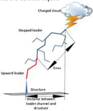
2.5.2 Leader Progression Model
495
attracted towards the earthed object.
Fig. 6. Leader Progression Process
Since the stepped leader propagation is non-predictable, several researchers have made various assumptions to create leader progression models. The first model indicated in [65] foresees that when a stepped leader enters a given volume with a specific amount of charge, it will be attracted by a structure after reaching a certain critical volume of the structure.
Different leader charges are being used to calculate the collection volume. The attractive radius (R) is expressed as
𝑅 = 𝐼 0.84 . (8)
Where 𝑎 = 0.7 . , h is the tower height, I is the maximum
current. Further researchers have applied the collection volume to analyse the lightning strikes to buildings by using field intensification or collection volume method, which helps in placing the air terminals on grounded structures. However, detailed studies in [66-68] by several researchers have indicated that there has been no proper validation for this method in the lightning research community as the lightning attractive zones predicted are observed to be grossly large and considered to be unrealistic. Additionally, researchers [69, 70] presumed that the leaders propagate along the path of maximum electric field. In this model, the electric field generated by the cloud has been simulated with non-varying charge density. The charge of the downward leader remains same throughout the channel and the equation is given by
𝜌 = 3.8 × 10 𝐼 . (9)
Furthermore, researchers [71, 72] have assumed that the transmission of downward leader is independent of its electric field and also the charge in the channel linearly declines with increase in the altitude, where it attains peak and becomes zero at the tip of downward leader and cloud level respectively. The potential of the connecting leader is evaluated by
𝛥𝑈 = 𝑙𝐸 + 𝑥 𝐸 ln [ − 𝑒( )] (10)
Where 𝑙 refers to the length of leader channel, 𝐸 refers to the minimum positive streamer gradient, 𝐸 refers to the final quasi-stationary streamer gradient, 𝑥 = 𝑣𝜃, 𝜃 refers the arc time constant and 𝑣 is the speed of the ascending positive leader. Later a new model [73] has been introduced, where it uses time-dependent inception model to analyse the propagation of return stroke till its interaction with the downward tip of the stepped leader. This model has analysed the characteristics of the lightning physical properties with the
help of leader hydrodynamical model.
The charge per unit length required to thermalize a new leader segment is computed by
𝑞𝐿 =
( ( )) ∫ ( . )
(11)
Where IL represents the leader current, fert represents the total amount of energy that is being transferred in the form of electronic, rotational and translational excitation, fv relates to a small amount of collision energy that is being transferred to vibrational reservoir,
represents a vibrational energy,
𝜏
refers to the leader transition time, 𝜏 refers to relaxation time.
2.5.3 Self-Consistent Lightning Interception Model (SLIM)
The model hypothesis that there exists a computational difference between the geometrical and actual potential distributions after formation of corona during the estimation of the total charge distribution during corona at the front of the leader tip [74]. The attractive radius as a function of return stroke peak current and structure height is given by
𝑅 = 1.86 × 𝐼 . (12)
Where 𝑎 = −1.617 × 10 + 0.6417 . , h is the structure
height
Equation 12 is applicable for narrow structures with axial symmetry and cannot be used to compute the attractive radius of the other structures, as the attractive zone is dependent of maximum current of the return stroke and geometry of the point of interest.
3 CONCLUSIONS
It is evident from detailed discussions and analysis from preceding sections that several research groups have carried various exhaustive and substantial experimental studies to understand the phenomena of lightning return stroke modelling by utilizing the concepts of physics and electromagnetics. The important features and outcomes of return stroke models have been summarized and discussed elaborately. These return stroke models have been categorized with unique representation and characteristic features and are summarized:
1. In the case of Gas Dynamic Models, laws of conservation of mass, momentum and energy have been fundamentally used to analyse the radial evolution of a short segment of lightning channel and its shock wave. The model outcomes are temperature, pressure and mass density.
2. Electromagnetic Models mainly relate to the application of Maxwell‘s equations utilized in a lossy antenna which is approximated to that of a lightning channel. The model proposes a set of outcomes which specifically includes the distribution of current along the channel which in turn helps in obtaining the remote electric and magnetic fields. 3. Distributed Circuits are representation of transmission line model which are used for the approximation of electromagnetic models. These models represent the transient process on a vertically modelled transmission line.
496 IJSTR©2020
model representation. The effectiveness of such models stems from the strengths of the representation of each model type as well as the simplicity in its return stroke model representation.
5. It is evident from detailed analysis and based on the deliberations as a part of this research study that the models of lightning return strokes are essential for estimating various parameters of the lightning properties in addition to providing a mechanism to carry out risk assessment during lightning strokes.
a. It is also hence inferred that for computation of lightning protection zone it is imperative to obtain a significantly accurate estimate of characteristics namely the striking distance and return stroke current from the parameter and equations governing the return stroke models.
b. On similar lines, evaluation of the impact and consequent damage due to lightning strokes on structures are meaningfully ascertained based on the considerably correct estimate of the speed and the energy of the stepped leader.
c. Hence, risk due to lightning strokes based on the relative type of utility can be evaluated more meaningfully and enable evolving an appropriate lightning protection system for various structures and allied man-made buildings.
ACKNOWLEDGMENT
The corresponding author of this research work is grateful to the Department of Science & Technology (DST) - Government of India for sanctioning and funding the Bilateral India-Sri Lanka Research Project Grant No.: DST/INT/SL/P-14/2016/C&G which forms a part of this research study.
REFERENCES
[1] V. Cooray, ―The lightning flash,‖ IET, 2014.
[2] Shi, Wei, Qingmin Li, and Li Zhang, ―A stepped leader model for lightning including charge distribution in branched channels,‖ J. App. Phys., Vol. 116, no. 10, (2014).
[3] A. Gayen, A. Dhar, B. N. Das, and D. R. Poddar, ―A Simplified Approach to Understanding of the Phenomenon of Cloud to Ground Lightning and Modeling of Return Stroke Current,‖ Proc. 9th Int. Conf. Electromagn. Interf. Compat. (INCEMIC), no. 1, pp. 258–362, (2006).
[4] M.A. Uman, ―The Lightning Discharge,‖ San Diego, CA: Acadamic, 1987.
[5] V. Cooray, ―Lightning electromagnetics,‖ IET, 2012. [6] C. Gomes and V. Cooray, ―Concepts of lightning return
stroke models,‖ IEEE Trans. Electromagn. Compat., Vol. 42, no. 1, pp. 82–96, (2000).
[7] Y. Lin, M. Uman, and R. Standler, ―Lightning return stroke models,‖ J. Geophys. Res., Vol. 85, no. 9, pp. 1571–1583, 1980.
[8] V. A. Rokov, and M. A. Uman, ―Lightning: physics and effects,‖ Cambridge University Press, 2003.
[9] V. A. Rakov and M. A. Uman, ―Review and evaluation of lightning return stroke models including some aspects of their application,‖ IEEE Trans. Electromagn. Compat., Vol. 40, no. 4 PART 2, pp. 403–426, 1998.
[10]S. I. Drabkina, ―The theory of the development of the spark channel,‖ J. Exper. Theoret. Phys., Vol. 21, pp. 473– 483, 1951. (Engl. transl. AERE LIB/Trans. 621, Harwell,
Berkshire, U.K.).
[11]S. I. Braginski, ―Theory of the Development of a Spark Channel,‖ J. Exptl. Theor. Phys., Vol. 34, no. 34, pp. 1548–1557, 1958.
[12]R. D. Hill, ―Channel heating in return-stroke lightning,‖ J. Geophys. Res., Vol. 76, no. 3, p. 637, 1971.
[13]R. D. Hill, ―Energy dissipation in lightning,‖ J. Geophys. Res., Vol. 82, pp. 4967–4968, 1977.
[14]E. P. Krider, G. A. Dawson, and M. A. Uman, ―The peak power and energy dissipation in a single-stroke lightning flash,‖ J. Geophys. Res., Vol. 73, pp. 3335–3339, (1968). [15]M. N. Plooster, ―Shock Waves from Line Sources.
Numerical Solutions and Experimental Measurements,‖ Phys. Fluids, Vol. 13, no. 11, p. 2665-2675, 1970.
[16]M. N. Plooster, ―Numerical Simulation of Spark Discharges in Air,‖ Phys. Fluids, Vol. 14, no. 10, p. 2111-2123, 1971.
[17]M. N. Plooster, ―Numerical Model of the Return Stroke of the Lightning Discharge,‖ Phys. Fluids, Vol. 14, no. 10, pp. 2124–2133, 1971.
[18]J. E. Borovsky, ―Lightning energetics: Estimates of energy dissipation in channels, channel radii, and channel-heating risetimes,‖ J. Geophys. Res., Vol. 103, pp. 11537– 11553, 1998.
[19]A. H. Paxton, R. L. Gardner, and L. Baker, ―Lightning return stroke. A numerical calculation of the optic radiation,‖ Phys. Fluids, Vol. 29, no. 8, pp. 2736–2741, 1986.
[20]E. I. Dubovoy, V. I. Pryazhinsky, and V. E. Bondarenko, ―Numerical modelling of the gasodynamical parameters of a lightning channel and radio-sounding reflection,‖ Izvestiya AN SSSR-Fizika Atmosfery I Okeana, Vol. 27, pp. 194–203, 1991.
[21]A. S. Podgorski and J. A. Landt, ―Three-Dimensional Time Domain Modeling of Lightning,‖ IEEE Power Eng. Rev., Vol. PER-7, no. 7, pp. 72–73, 1987.
[22]R. Moini, V. A. Rakov, M. A. Uman and B. Kordi, ―An antenna theory model for the lightning return stroke,‖ Proc. 12th Int. Zurich Symp. Electromag. Compat., Zurich, Switzerland, pp. 149–152. Feb. 1997.
[23]Baba. Yoshihiro and V. A. Rakov, ―Electromagnetic models of the lightning return stroke,‖ J. Geophys. Res.: Atmospheres, Vol. 112, no. D4, 2007.
[24]Shoory, Abdolhamid, Rouzbeh Moini, SH Hesam Sadeghi and V. A. Rakov, ―Analysis of lightning-radiated electromagnetic fields in the vicinity of lossy ground,‖ IEEE Trans. Electromagn. Compat., Vol. 47, no. 1, pp. 131-145, 2005.
[25]Y. Baba and M. Ishii, ―Characteristics of electromagnetic return-stroke models,‖ IEEE Trans. Electromagn. Compat., Vol. 45, no. 1, pp. 129–135, 2003.
[26]J. E. Borovsky, ―An electrodynamic description of lightning return strokes and dart leaders: Guided wave propagation along conducting cylindrical channels,‖ J. Geophys. Res., Vol. 100, no. D2, p. 2697, 1995.
[27]Chen, K, ―Transient response of an infinite cylindrical antenna,‖ IEEE Trans. Antennas Propagat., Vol. 31, no. 1, pp. 170-172, 1983.
[28]CIGRE TF 33.01.03, ―Lightning Exposure of Structures and Interception Efficiency of Air Terminals,‖ CIGRE Rep. 118, no. 3, Oct., p. 89, 1997.
497
hybrid electromagnetic model,‖ J. Electrostat., Vol. 60, no. 2-4, pp. 111-120, 2004.
[30]C. E. Baum and L. Baker, ―Analytic return-stroke transmission-line model,‖ Light. Electromag., New York: Hemisphere, pp. 17–40, 1990.
[31]G. H. Price and E. T. Pierce, ―The modelling of channel current in the lightning return stroke,‖ Radio Sci., Vol. 12, pp. 381–388, 1977.
[32]P. F. Little, ―Transmission line representation of a lightning return stroke,‖ J. Phys. D: Appl. Phys., Vol. 11, pp. 1893– 1910, 1978.
[33]N. Takagi and T. Takeuti, ―Oscillating bipolar electric field changes due to close lightning return strokes,‖ Radio Sci., Vol. 18, pp. 391–398, 1983.
[34]D. W. Quinn, ―Modeling of lightning,‖ Math. Comput. Simul., Vol. 29, no. 2, pp. 107–118, 1987.
[35]M. A. Da Frota Mattos and C. Christopoulos, ―A nonlinear transmission line model of the lightning return stroke,‖ IEEE Trans. Electromagn. Compat., Vol. 30, no. 3, pp. 401–406, 1988.
[36]M. A. da F Mattos and C. Christopoulos, ―A model of the lightning channel, including corona, and prediction of the generated electromagnetic fields,‖ J. Phys. D. Appl. Phys., Vol. 23, no. 1, pp. 40–46, 1990.
[37]M. V. Kostenko, ―Electrodynamic characteristics of lightning and their influence on disturbances of high-voltage lines,‖ J. Geophys. Res. Atmos., Vol. 100, no. D2, pp. 2739–2747, 1995.
[38]V. Amoruso and F. Lattarulo, ―The Electromagnetic Field of an Improved Lightning Return-Stroke Representation,‖ IEEE Trans. Electromagn. Compat., Vol. 35, no. 3, pp. 317–328, 1993.
[39]S. Visacro and A. De Conti, ―A distributed-circuit return-stroke model allowing time and height parameter variation to match lightning electromagnetic field waveform signatures,‖ J. Geophys. Res. Lett., Vol. 32, no. 23, pp. 1– 5, 2005.
[40]V. A. Rakov, ―Some inferences on the propagation mechanisms of dart leaders and return strokes,‖ J. Geophys. Res.: Atmospheres, Vol. 103, no. D2, pp. 1879-1887, 1998.
[41]G. N. Oetzel, ―Computation of the diameter of a lightning return stroke,‖ J. Geophys. Res., Vol. 73, no. 6, pp. 1889– 1896, 1968.
[42]H. Norinder, ―Quelques essais recents relatifs a¨ la determination des surtensions indirectes,‖ CIGRE, Paris, pp. 303, 29th Jun. – 8th Jul. 1939.
[43]C. E. R. Bruce and R. H. Golde, ―The lightning discharge,‖ J. Inst. Elect. Eng., Vol. 88, pp. 487–520, 1941.
[44]R. Lundholm, ―Spectral theory of quantum systems with exotic symmetries,‖ Ph.D. dissertation, KTH, Stockholm, Sweden, 1957.
[45]A. S. Dennis and E. T. Pierce, ―The return stroke of the lightning flash to earth as a source of VLF atmospherics,‖ J. Res. Natl. Bur. Stand. Sect. D Radio Sci., Vol. 68D, no. 7, p. 777, 1964.
[46]M. A. Uman and D. K. Mclain, ―Magnetic Field of Lightning Return Stroke,‖ J. Geophys. Res., Vol. 74, pp. 6899–6910, 1969.
[47]V. Cooray and R. E. Orville, ―The effects of variation of current amplitude, current risetime and return stroke velocity along the return stroke channel on the electromagnetic fields generated by return strokes,‖ J.
Geophys. Res., Vol. 95, no. D11, pp. 18617–18630, 1990. [48]V. Rakov and A. A. Dulzon, ―A modified transmission line
model for lightning return stroke field calculations,‖ Proc. 9th Int. Symp. Electromagn., pp. 229–234, 1991.
[49]M. Master, Y. T. Lin, M. A. Uman and R. B. Standler, ―Calculations of lightning return stroke electric and magnetic fields above ground,‖ J. Geophys. Res., Vol. 86, pp. 12127–12132, 1981.
[50]F. Rachidi, and C. A. Nucci, ―On the Master, Uman, Lin, Standler and the modified transmission line lightning return stroke current models,‖ J. Geophys. Res.: Atmospheres, Vol. 95, no. D12, pp. 20389-20393, 1990. [51]V. Cooray and N. Theethayi, ―Effects of corona on pulse
propagation along transmission lines with special attention to lightning return stroke models and return stroke velocity,‖ Proc. VIII Int. Symp. Light. Prot., Brazil, (2005). [52]C. F. Wagner, ―A new approach to the calculation of the
lightning performance of transmission lines,‖ AIEE Trans., Vol. 75, pp. 1233–1256, 1956.
[53]F. Heidler, ―Traveling current source model for LEMP calculation,‖ Proc. 6th Int. Symp. EMC, Zurich, Switzerland, 29F2, pp. 157–162, 1985.
[54]P. Hubert, ―New model of lightning return stroke – confrontation with triggered lightning observations,‖ Proc. 10th Int. Aerospace and Ground Conf. Lightning and Static Electricity, pp. 211–215, Paris, 1985.
[55]V. Cooray, ―A return stroke model,‖ Proc. Int. Conf. Lightning and Static Electricity, University of Bath, Sep. 1989.
[56]V. Cooray, ―A model for the subsequent return strokes,‖ J. Electrostat., Vol. 30, pp. 343–354, 1993.
[57]G. Diendorfer and M. A. Uman, ―An improved return stroke model with specified channel base current,‖ J. Geophys. Res., Vol. 95, pp. 13621–13644, 1990.
[58]R. Thottappillil, D. K. Mclain, M. A. Uman and G. Diendorfer, ―Extension of Diendorfer-Uman lightning return stroke model to the case of a variable upward return stroke speed and a variable downward discharge current speed,‖ J. Geophys. Res., Vol. 96, pp. 17143–17150, 1991.
[59]R. Thottappillil and M. A. Uman, ―Lightning return stroke model with heightvariable discharge time constant,‖ J. Geophys. Res., Vol. 99, pp. 22773– 22780, 1994.
[60]V. Cooray, ―Predicting the spatial and temporal variation of the current, the speed and electromagnetic fields of subsequent return strokes,‖ IEEE Trans. Electromagn. Compat., Vol. 40, pp. 427–435, 1998.
[61]V. Cooray and V. Rakov, ―A current generation type return stroke model that predicts the return stroke velocity,‖ J. Light. Res., Vol. 1, pp. 32–39, 2007.
[62]V. Cooray, R. Montano and V. Rakov, ―A model to represent first return strokes with connecting leaders,‖ J. Electrostat., Vol. 40, pp. 97–109, 2004.
[63]V. Cooray, ―A novel procedure to represent lightning return strokes – current dissipation return stroke models,‖ IEEE Trans. EMC, Vol. 51, pp. 748 – 755, 2009.
[64]A. J. Eriksson, ―An improved electrogeometric model for transmission line shielding analysis,‖ IEEE Power Engg. Review., Vol. 2, no. 3, pp. 871–77, 1987.
498 IJSTR©2020
[66]Mousa, Abdul M., ―Proposed research on the collection volume method/field intensification method for the placement of air terminals on structures,‖ Power Engineering Society General Meeting, IEEE, Vol. 1, pp. 301-305, 2003.
[67]Hartono, Z. A., and I. Robiah, ―The field intensification method (FIM): An assessment based on observed bypass data on real buildings in Malaysia,‖ Public comment submitted to the Australian standardization committee, EL-24, 2002.
[68]L. Dellera and E. Garbagnat, ―Lightning strike simulation by means of the Leader Progression Model, Part I: Description of the model and evaluation of free-standing structures,‖ IEEE Trans. Power Deliv., Vol. 5, no. 4, pp. 2009-2022, 1990.
[69]L. Dellera and E. Garbagnati, ―Lightning strike simulation by means of the Leader Progression Model: II. Exposure and shielding failure evaluation of overhead lines with assessment of application graphs,‖ IEEE Trans. Power Deliv., Vol. 5, no. 4, pp. 2023-2029, 1990.
[70]F. Rizk, ―Modelling of transmission lines: exposure to direct lightning strokes,‖ IEEE Trans. Power Deliv., Vol. 5, no. 4, pp. 1983-1997, 1990.
[71]F. A. M. Rizk, ―Modeling of Lightning Incidence to Tall Structures Part II: Application,‖ IEEE Trans. Power Deliv., vol. 9, no. 1, pp. 172–193, 1994.
[72]M. Becerra and V. Cooray, ―A self-consistent upward leader propagation model,‖ J. Phys. D. Appl. Phys., Vol. 39, no. 16, pp. 3708–3715, 2006.
[73]M. Becerra and V. Cooray, ―On the velocity of positive connecting leaders associated with negative downward lightning leaders,‖ J. Geophys. Res. Lett., Vol. 35, no. 2, 2008.
[74]V. Cooray, ―The lightning flash,‖ IET, 2014.
[75]Shi, Wei, Qingmin Li, and Li Zhang, ―A stepped leader model for lightning including charge distribution in branched channels,‖ J. App. Phys., Vol. 116, no. 10, 2014. [76]A. Gayen, A. Dhar, B. N. Das, and D. R. Poddar, ―A
Simplified Approach to Understanding of the Phenomenon of Cloud to Ground Lightning and Modeling of Return Stroke Current,‖ Proc. 9th Int. Conf. Electromagn. Interf. Compat. (INCEMIC), no. 1, pp. 258–362, 2006.