IJEDR1402031
International Journal of Engineering Development and Research (www.ijedr.org)1485
Intelligent Propagation Display
1
Kanaujia Rohit Singh. K, 2Mishra Nilesh.P, 3Christie Lionel. S, 4Patel Rinkesh. S
Government Engineering College, Bharuch
_______________________________________________________________________________________________________
Abstract -This paper is based on our project named as Propeller clock Display. It can be called as 7 LEDs innovation. Here 7 LEDs are used which are displaying digital and analog time programmed by the microcontroller. Decoder IC is used to decode IR waves from the remote and insert the time we desire. This feature creates wireless communication between the display and the input applied. The motor used rotates at a very fast speed and this display is achieved. The basic idea is based on Propeller mechanism. Entire display is done by using 7 LEDs only which are rotated at f i x e d speeds by DC motor. This kind of display can be useful anywhere where size, speed and cost matters.
Keywords - Hall Effect Sensor, IR Decoder IC, Microcontroller, Persistence of Vision, 7 LEDs
_______________________________________________________________________________________________________
I. INTRODUCTION
Project’s aim is to control LEDs connected in a row to display some images, and function it as a clock that may be analog or digital. For example: at the doors for displaying time in analog and digital form, applications using analog and digital presentations simultaneously etc. It can be used in industries, and other application where automatic display is needed.
The implemented LEDs turn on and off, very rapidly one after other. Naturally the human eye responds slowly and we get an impression that the lights are on all together making the display readable. A few LEDs placed in a row are attached to a rotating board. They turn on and off at very definite and precise time intervals. All we can see are the lighted dots from the LEDs making a readable display that seems to float.
In the project an array of LEDs, microcontroller, and infrared receiver are placed on the board and are rotated by a motor at a very high rpm. Since microcontroller is programmed using certain algorithm so at the same time, the board functions as a clock. Automatic control is achieved by using an Infrared remote control for time setting and function selecting like switching from analog to digital mode or vice versa This gives an idea that the display is an automatic clock either in digital mode or analog mode.
II. SCANNINGMECHANISM
Mechanical scanning is performed in the clock. When the motor is turned on, the connected seven LEDs are scanned line by line at a very fast speed which makes the observer to observe those LEDs as a display clock rather simple seven LEDs.
III. PROCESSINGCOMPONENT
89C52 Microcontroller
Atmel’s 89c52 Microcontroller IC is used in the project [3]. The entire processing depends upon programming the microcontroller. 89c51 is a slightly slow than Atmel 89c52 so we preferred it. It has high performance, reliability and is fabricated using high-density CMOS technology and is functionally compatible with the industry standard 80C51 microcontrollers. It has 8-Kbytes of Flash memory, 258 x 8 RAM, 4 programmable I/O port lines; 32 I/O lines for input and output purpose, a serial I/O port for either multiprocessor communications, I/O expansion or full duplex UART, three 16-bit timer/counters; an eight- source, two-priority-level, nested interrupt structure; and an on-chip oscillator and clock circuit. Maximum speed is upto 40 MHz at 5V supply voltage. Its simplicity compelled us to use it in our project.
IV. IMPLEMENTATIONMATERIAL
A. Hall Effect Sensor
Sensors are most important tool used in any project. A sensor that gives variation in the output voltage with reference to the change in the magnetic field is called a hall affect sensor. It can be used for switching and speed detection purposes. In the working scenario electricity carried through a conductor will produce a magnetic field that varies with current, and an interesting feature of this sensor is, it can be used to measure the current without interrupting the circuit.
They are also used with brushless DC motors to detect the position of the permanent magnet. The need of this sensor in this project is to detect the position of permanent magnet and produce respective voltage which in turn controls the rotation. This makes the clock display clear.. When used with microcontrollers or microprocessors they may require some interfacing circuitry. The interface section basically depends upon the sensor used.
B. Encoder
IJEDR1402031
International Journal of Engineering Development and Research (www.ijedr.org)1486
C. DecoderA Decoder decodes an encoded signal or encoded data. They are helpful in retrieving the data that had been encoded.Whenever encoders are used they are complimented by decoders as well. Here both are used to decode and encode the information obtained from the sensor for the microcontroller to process. Here TX-2B is used for decoding purpose. It is a CMOS LSI designed for remote controlled applications. It is shown in Fig 1
Fig 1Pin configuration of TX-2B D. LEDs
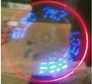
Seven Blue LEDs are used to display clock digits for digital clock and clock arms for analog clock time period. One red LED is used to make a circular frame, while one yellow LED is used to form numbers in the analog clock. This is shown in Fig 2 and 3.
Fig 2: Analog View: Propeller clock in analog mode
Fig 3: Digital Display view
E. IR Transmitter
IJEDR1402031
International Journal of Engineering Development and Research (www.ijedr.org)1487
V. BLOCKDIAGRAM
General block diagram is shown in Fig 4.
It contains an IR receiver, next to it is the Atmel’s microcontroller and the output is achieved on the seven connected LEDs. The sensing effects are checked using hall effect sensor.
Fig 4: General Block Diagram
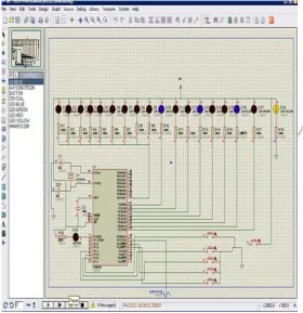
VI. CIRCUITDIAGRAM
Fig 5: Schematic Diagram
VII. OPERATIONALINSTRUCTIONS
First connect the motor to with a 5V DC power supply. Turn on the power supply of the motor, it will rotate and finally the rotation reaches a steady state and those seven LEDs will transform into an image. Though it is not an image but the speed makes it to view like an image, same as it happens in cartoon films. Button 1 is used for the arrangement of “seconds”, button 2 for “minutes” and “hour”. Button 4 to start the clock. Press 3 to switch between analog and digital mode.
IJEDR1402031
International Journal of Engineering Development and Research (www.ijedr.org)1488
Fig 7: Rotation at moderate speed
VIII. SIMULATIONSOFTWAREANDTOOLS
Few softwares and Simulators are used like, Edsim Simulator, Multisim 11 and Microvision Keil. Edsim Simulator is used to perform simulation of Assembly code, so first we checked our program in Edsim and checked all the values of registers like Accumulator and so on. In Multism11 we designed the schematic of the project. Microvision Keil software was used to convert the Assembly code to HEX file and for uploading the program from the computer to programmer. We have used ATMEL series programmer in which we can program various ATMELs ICs and AVR too.
IJEDR1402031
International Journal of Engineering Development and Research (www.ijedr.org)1489
Fig 9: Remote Control Circuit Diagram in Multisim 11
IX. RESULTSANDDISCUSSION
Speed of the LED's (Frame rate)
The rotational speed of the LED's affects directly how many pictures can be displayed in a Second. This corresponds to the frame rate. On a modern TV, the frame rate is 100Hz. More the frame rate, the less flickering of the picture. Because on the Propeller Display the picture is scanned mechanically, it is not easy to achieve high frame rates. The propeller has to be very well balanced to keep vibrations as low as possible and keep the speed of the rotating LED's as high as possible.
Let’s see how fast the LED's rotated when a picture is displayed with a frame rate of 25Hz. Speed is represented by Here is the Calculation.
Acceptance:
f = 25Hz (Frame rate) r = 0.2 m
(Radius from centre of rotation to the LED's) v = f (2 π r) 3600 (2 π r) = 2 * 0.2 * 3.141 = 1.256
v = 25 (1.256) 3600 = 113040 meter/ hour Let’s see what is the speed if radius is 0.8m? Here is the Calculation.
Acceptance:
f = 25Hz (Frame rate) r = 0.8 m
v = f (2 π r) 3600 (2 π r) = 2 * 0.8 * 3.141 = 5.0256 v = 25 (5.0256) 3600 = 452304 meter/ hour
We see that already a slow frame rate of 25Hz generates very high speeds on the LED's. The bigger the radius of the display, the bigger is the speed and more vibrations occur.
X. CONCLUSION
The idea behind the project was using the propeller mechanism to design a display. We chose a clock as our display idea and successfully implemented it. The clock works in both modes analog and digital Interesting feature was making it remote control and wireless. It was also achieved using IR sensor. This project is helpful wherever there is a need of automatic display.
XI. ACKNOWLEDGMENT
We thank Almighty ALLAH, we express our sincere gratitude to our worthy director and the coauthor of the paper Dr. .Asad Ali Shaikh and last but not the least we thank our parents.
REFRENCES
IJEDR1402031
International Journal of Engineering Development and Research (www.ijedr.org)1490
[2] Saito, Y.; Ogawa, A.; Negoto, H.; Ohnishi, K.; (2005), “Development of intelligent prosthetic hand adapted to ageand body shape”Rehabilitation Robotics, 2005. ICORR 2005. 9th International Conference, 28 June-1 July 2005 Page(s):389 - 430 .Digital Object Identifier 10.1109/ICORR.2005.1501125.
[3] “Embedded controller for the 8051 Family” by William H. Payne, Hardcover: 528 pages; Academic Press; ISBN: 0125475705.[2] “The 8051 Microcontroller: Architecture, Programming, and Applications” by Kenneth J. Ayala.