Three Phase Four Wire Hybrid System for
Loads in Isolation
Mukesh Sahi1, Dr. Dinesh Birla2
PhD Scholar, Pacific University, Udaipur, Rajasthan, India
Professor & Head of Department Electrical Engineering RTU, Kota, Rajasthan, India
ABSTRACT: The wind driven self excited induction generator and permanent magnet synchronous generator (PMSG)
with solar photovoltaic (SPV) power generating system are combined to feed the linear/non-linear balanced/unbalanced loads in isolated regions. Powers from all sources are combined at common coupling point with battery energy storage system (BESS). Nonlinear and unbalanced loading condition demands reactive power from the system. Whole system with load side controller is simulated in the matlab simulink to show the system performance during nonlinear and unbalanced loading condition. Source side controller maintains the PMSG output maximum.
KEYWORDS: Voltage Stability, Wind Turbine, Squirrel-Cage Induction Generator, PMSG, SPV, Common Coupling
Point, BESS.
I. INTRODUCTION
Due to increased environmental concern, electrical power generation from renewable energy sources such as wind, solar is increased. They have come of ages and are the world’s fastest growing energy resources. These are clean and effective modern technology that provides a beacon of hope for a future based on sustainable and pollution free technology. These renewable energy sources are located in remote regions, thereby causing obstacles in their development. In starting during the development of the wind generation for grid connected systems, the fixed speed wind turbines with squirrel cage induction generators have been in use. For such systems the energy conversion efficiency is very low. Now these days variable speed wind energy conversion system (WECS) [1-4] uses the maximum power tracker (MPT) [5] which adjusts the rotational speed to maximize the wind turbine output power. The turbines driving permanent magnet synchronous generators (PMSG) are gaining popularity among the variable-speed wind turbines [6]. A PMSG is a rotating electric machine, in which the field excitation is provided by permanent magnets. PMSGs have a loss-free rotor, and the power losses are confined to the stator windings and the stator core [7]. A multi-pole PMSG [8] connected to a power converter can operate at low speeds so that a gear can usually be omitted. A gearless construction represents an efficient and robust solution for a WECS.
Thus, the efficiency of a PMSG-based WECS has been assessed higher than other variable-speed wind turbine systems. However, the disadvantage of PMSGs is the high cost of permanent magnet material in present time, which is expected to reduce in the near future. Full scale power converter is used in the case of PMSG-based WECSs, which allows the full controllability of the system [9]. The power converter decouples the PMSG from the grid and results in an improved reliability.
II. SYSTEM
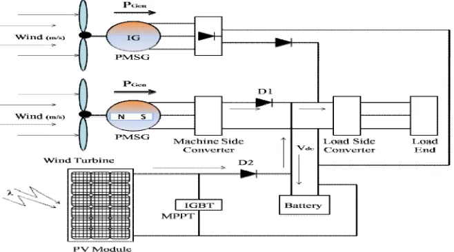
other variable-speed wind turbine systems [11]. In the case of PMSG based WECS, a full scale power converter is used, which allows the full controllability of the system. In such systems, the power converter decouples the PMSG from the grid, resulting in an improved reliability. For stand-alone systems supplying local loads, if the extracted power from the wind is more than the local loads (and losses), the excess power is required to be diverted either to a dump load or to be stored in the battery bank. Moreover, when the extracted power is less than the load power, the deficit power needs to be supplied from a storage element like a flywheel, a super capacitor, compressed air, hydrogen storage, a secondary battery [12]. A number of attempts have been made to address the issues of voltage and frequency control (VFC) for stand-alone systems using asynchronous generators [13][14][15][16]. Attempts are made to develop a battery-based controller for a wind-driven autonomous four-wire system using a PMSG and feeding local loads in stand-alone mode without mechanical position sensors. Further this autonomous WECS using PMSG is considered in a hybrid system with the Solar system using photovoltaic array. As solar power is an endless source of energy like wind energy, so developing a hybrid system based on these two freely available energies is a need of the present world. The Three energy sources PMSG, IG and SPV are connected in parallel to a common DC bus line as shown in fig. 1, through their individual converters. The load may be dc-connected to the dc bus line or may include an IGBT based pulse width modulated (PWM) voltage source inverter to convert the DC power into AC at 50 or 60 Hz. Each source has its individual control. The diodes, D1, D2 and D3, allow only unidirectional current flow from the source to the DC bus line, thus keeping each source from acting as a load on each other or on the battery. Therefore, in the event of malfunctioning of any of the energy sources, the respective diode will automatically disconnect that source from the system. The output of the hybrid generating system goes to the DC bus line to feed the isolating DC load or to the inverter, which converts the DC into AC. When the output of the system is not available, the battery powers the DC load or discharges to the inverter to power AC loads.
III. PRINCIPLE
The operating principle of the controller which controls the load-side converter is based on the control of the reactive power to regulate the magnitude of the load voltage and active power to regulate the frequency of the voltage. The battery system absorbs the excess active power when the frequency of the load voltage is above the nominal frequency, and it supplies the active power when the frequency is below the nominal frequency. When the magnitude of the voltage falls below the reference value, the load-side converter provides the reactive power, and when the magnitude of the voltage rises above the reference value, the reactive power is absorbed by the load-side converter.
For the control of the load-side converter, the reference three-phase phase-to-neutral voltages are compared with the sensed three-phase phase-to-neutral voltages at the load end, and the difference is fed to the voltage controller. The output of the voltage controller gives the reference three-phase load-side converter currents, which are compared with the sensed three-phase load-side converter currents to achieve control signals for the load side converter.
A. MACHINE SIDE CONVERTER CONTROL
The operating principle of the controller for the machine-side converter is based on the decoupled control of the d- and q-axis stator currents of the PMSG with the d-axis aligned to the permanent magnet flux or rotor electrical axis. Speed Control Loop for Maximum Power Tracking and Reference Generation for q-Axis Stator Current. In the proposed algorithm, the wind speed is sensed for the MPT. The rotor position (Ѳ ). is estimated using stator flux linkages. The rotor speed (ω ) is determined from the rotor position (Ѳ ). The reference rotor speed (ω∗) for the MPT is generated from the wind speed and the optimum tip speed ratio and compared with (ω ) to calculate the rotor speed error (ω ). At the nth sampling instant, the output of the proportional-integral (PI) speed controller with proportional gain K ω and integral gain Kω gives reference for the q-axis stator current(I ). To obtain maximum torque with
minimum stator current, the reference d-axis stator current (I∗ ) is set to zero.
B. LOAD SIDE CONVERTER CONTROL
The purpose of the load-side converter is to maintain rated voltage and frequency, irrespective of connected load. The power balance of the load-side converter is maintained by diverting excess power generated to the battery in the DC link of back-to-back connected PWM converters or by supplying active power from the battery in the case of a deficit between the generated power and load requirement. Similarly, the required reactive power for the load is supplied by the load-side converter to maintain a constant value of the load voltage. The reference voltages (v∗ , v∗
, and v∗ ) for
the control of the load voltages at time t are given as-
v∗ =√2V sin(2πft) (5.7)
v∗ =√2V sin(2πft−120°) (5.8)
v∗ =√2V sin(2πft + 120°) (5.9)
Where, ‘f’ is the nominal frequency (50 Hz), and V is the RMS phase-to-neutral load voltage. The load voltages (v ,
v , and v ) are sensed as feedback signals. The error voltages (v , v , and v ) at the nth sampling instant are calculated from the reference voltages and load voltages. The reference three-phase load-side converter currents (i∗ , i∗ , and i∗ ) are generated by feeding the voltage error signals to the PI voltage controllers with proportionate
gain as K and integral gain as K .
The reference three phase load side converter currents are then compared with sensed load side converter currents (i , i , and i ) to compute the load side converter current errors.These current errors are amplified with gain (K), and the amplified signals are compared with the fixed frequency (Z kHz) triangular carrier wave of unity amplitude to generate gating signals for IGBTs of the load-side converter.
IV. SIMULATION AND RESULTS
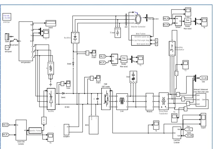
Figure 2: Simulation diagram for the system under consideration.
A. SOURCE SIDE CONTROLLER
The objective of the source side controller is to achieve a maximum torque for the maximum power tracking with minimum currents. The graphs for the source side converter are shown in fig. 6.31. The output of the Wind turbine driven PMSG is maximized by using maximum power tracking technique and simulated as source side controller. Graphs are plotted between the time and the various observed quantities. The input and output of the system are shown through the graph placed in the fig 6.31. In fig. 6.31(a) the first graph shows Cos and Sin values created through PLL by using the three phase per unit voltages generated by PMSG. These Cos and Sin values are used to convert the ‘dq0’ values to three phase ‘abc’ values. Fig. 6.31(b) & fig. 6.31(c) represent the input and output values of the PI controller respectively. ‘dq0’ to three phase ‘abc’ conversion is shown in fig. 6.31(d). Three phase current generated through the PMSG is shown in fig. 6.31(e). Fig. 6.31(f) shows the result of subtraction of generated current shown in fig. 6.31(e) from the values shown in fig. 6.31(d). then these values are given to the PWM generator unit to generate the switching pulses for the source side controller. These switching pulses are shown in fig. 6.31(g).
Fig. 6.31 Source Side controller
wind sp eed
DC BUS Ws Wp Te Tm Wm A B C
wind generatio n
A B C a b c wind Discrete, Ts = 5e-006 s.
powergui
power1
10 0
Generator speed (pu) Pitch angle (deg) W ind speed (m/s) Tm (pu) Wind Turbine v + -v + -v + -z 1 A B C a b c n2 Three-Phase Transformer T7 T6 T5 T4 T3 T 2 T1 T +++
---Sub syste m Sp eed Vpu I Iref Source Side Con troller Scope 4 Scope3 Scope 1 Scop e
A B C + -Rectifire1 g A B C + -Rectifire
A B C A B C
R Signal(s) Pulses g A B C + -PWM IGBT Inverter A B C a b c
Me asu re1 Man ual Switch
Vlabc
ILabc Out1
L oad Sid e Co ntroller m A B C Tm Induction Generator
ABC
N Grounding Transformer [IL n_abc] Goto Iab c_Wind Vabc_ Wind [ILn_ abc] From5 Ia bc_B1 Vabc_B1 Iab c_B1 Vabc_ B1 V1 From Mean (discrete) Discrete Mea n valu e2
Mean (discrete)
Discrete Me an value1 Diode2 Diod e1 i + -i + -i + -i + -i + -12 C Conn1 Conn2 Conn3 Conn4 Ba lan ced / Unb alan ced Linea r / Non-Linear L oads
+ + + + -BESS
ABC
7 2 kvar
Vabc
Iabc PQ
3-ph ase 1
Vabc
IabcPQ
3-pha se
A B C
3 kvar A B C A B C
2 mH
B. LOAD SIDE CONTROLLER
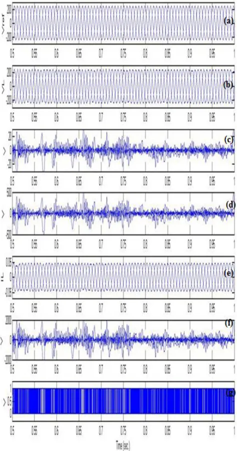
The objectives of the load-side converter are to maintain rated voltage and frequency, irrespective of connected load. The required reactive power for the load is supplied by the load-side converter to maintain a constant value of the load voltage. The graphs related to the load side controller are shown in Fig. 6. 32. In fig. 6.32(a) the first graph shows the three phase reference voltage. Fig. 6.32(b) represent the sensed three phase load voltage. The sensed three phase load voltage is subtracted from the reference three phase voltages and outcome is shown in fig. 6.32(d), which is directly entered to the PI controller. Fig. 6.32(e) shows the output of the PI controller. Sensed three phase load current is shown in fig. 6.32(e) is subtracted from the output of the PI controller shown in fig. 6.32(d) and the result of subtraction is shown in fig. 6.32 (f). Then these values of fig. 6.32 (f) are given to the PWM generator unit to generate the switching pulses for the load side controller. These switching pulses are shown in fig. 6.32(g).
C. LINEAR LOAD
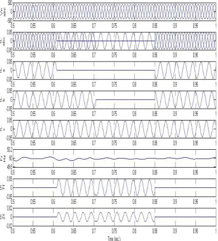
System is running with balanced load at starting. Now at 0.6 sec. an unbalance is created by disconnecting the phase ‘a’ from load, (by opening the connection between phase ‘a’ and its load). This will reduce the active power demanded by the load but cause supply imbalance which affects the source. Further at 0.7 sec. load form the phase ‘b’ is also removed, making the system more unbalanced. At 0.85 sec. both removed phases loads are connected again which makes the system a balanced one again. Behavior of the WECS using PMSG, IG, SP is shown by a set of waveforms in fig. 3. Here in the system during the unbalanced to maintain the constant frequency on the load side the extra active power is diverted to the BESS. It is clearly seen from the graphs that the load voltages for all three phases are in balanced condition. The system frequency remains always close to the 50 Hz.
Fig. 3 Graph for Linear Balanced/Unbalanced Load
D. NON-LINEAR BALANCED/UNBALANCED
System is started with balanced three phase load. At 0.6 sec. an unbalance is created by disconnecting a diode bridge rectifier load from phase ‘a’ (by opening the connection between phase ‘a’ and its load).
.
Further at 0.7 sec. load form the phase ‘b’ is also removed from its diode bridge rectifier load, making the system more unbalanced. At 0.85 sec. both removed phases loads are connected which places the system in the previous condition. It is clearly visible in fig. 4 that the voltage and frequency are almost constant even though during the disturbances.
V. CONCLUSION
Matlab/simulink based simulation of the proposed system shows that the voltage and frequency on load side remains balanced in all electrical loading conditions. The performance of the WECS using PMSG, IG, SPV system feeding balanced/unbalanced resistive, inductive, and non-linear load has been found satisfactory.
REFERENCES
[1] T. F. Chan, and L. L. Lai, “Permanent magnet machines for distributed power generation: A review,” IEEE Proceedings of the Power
Engineering Society General Meeting, pp. 1–6, June 2007.
[2] A. Rolan, A. Luna, G. Vazquez, “Modeling of variable speed wind turbine with a permanent magnet synchronous generator”, IEEE
International Conference on Electric Machines and Drives, pp. 734-739, July 2009.
[3] P. K. Goel, B. Singh, S. S. Murthy, N. Kishore, “Isolated wind-hydro hybride system using cage generators and battery storage,” IEEE
Transactions on Industrial Electronics, Vol. 58, No. 4, pp. 1141-1153, April 2011.
[4] M. Abdel-Salam, A. Ahmed, M. Abdel-Sater, “Harmonic mitigation, maximum power point tracking, and dynamic performance of variable-speed grid-connected wind turbine,” Electric Power Components and System, Vol. 39, No. 2, pp. 176-190, 02 Feb. 2011. [5] X. Yang, X. Gong, and W. Qiao, “Mechanical sensorless maximum power tracking control for direct drive PMSG wind turbine”, IEEE
Energy Conversion Congress and Exposition, pp. 4091-4098, sep. 2010.
[6] P. K. Goel, B. Singh, S. S. Murthy, and N. Kishore, “Autonomous hybrid system using SCIG for hydro power generation and variable speed PMSG for wind power generation”, IEEE Conference on Power Electronics and Drive Systems, pp. 55-60, nov. 2009.
[7] J. Faiz, B. M. Ebrahimi, M. rajabi-sebdani and A. Khan, “Optimal design of permanent magnet synchronous generator for wind energy conversion considering annual energy input and magnet volume”, IEEE Conference on Sustainable Power Generation and Supply, pp. 1-6, april 2009.
[8] S. Miyabukuro, M. Takiguchi,and R. Takhashi, “Modeling and simulation of wind turbine –fed interior permanent magnet synchronous generator”, IEEE Conference on Electrical Machines, pp. 1-6, sept. 2008.
[9] M. Chinchilla, S. Annaltes, and J. C. Burgos,, “Control of permanent-magnet generators applied to variable-speed wind energy systems connected to the grid,” IEEE Transactions on Energy Conversion, Vol. 21, No. 1, pp. 130–135, March 2006.
[10] E. Spooner, A.C. Williamson, G. Catto, "Modular design of permanent magnet generators for wind turbines," IEE Proceedings, Electric Power Applications, Vol.143, No. 5, pp. 388-395, Sep. 1996.
[11] J. Chen, C.V. Nayar, and L. Xu, "Design and finite-element analysis of an outer rotor permanent-magnet generator for directly coupled wind turbines," IEEE Transactions on Magnetics, Vol. 36, No.5, pp. 3802-3809, Sep 2000.
[12] K. Stunz, and J. Nedrud, “Multilevel energy storage for intermittent wind power conversion: Computer system analogies,” IEEE Power
Engineering Society General Meeting, pp. 1950–1951, San Francisco, CA, 12–16 June 2005.
[13] E. Mulzadi, and T. A. Lipo, “Series compensated PWM inverter with battery supply applied to an isolated induction generator,” IEEE
Transactions Industry Applications, Vol. 30, No. 4, pp. 1073–1082, July/August 1994.
[14] R.S Bhatia., D.K Jain., Bhim Singh and S.P. Jain, “Battery energy storage system for power conditioning of renewable energy sources”, in Proc. of IEEE Conference on Power Electronics and Drive Systems, Dec. 2005, pp.501-506.
[15] V. Valtchev, A. V. D. Bossche, J. Ghijselen, and J. Melkebeek, “Autonomous renewable energy conversion system,” Renewable Energy, Vol. 19, No. 1/2, pp. 259–275, January 2000.
[16] C. H. Lee and L. Wang, “A novel analysis of parallel operated self-excited induction generators”, IEEE Transactions on Energy