Construction of Digital Water Level Indicator
and Automatic Pump Controlling System
Md.Sourove Akther Momin
1*, Pratik Roy
2,Mr.Md.Golam Kader
3,
Md.Sahid Hasan
4,
Samiul Islam
5Department of Mechanical Engineering,Khulna University of Engineering & Technology,
Khulna-9203, BANGLADESH.
Corrosponding Author Email-
[email protected]
Abstract:
In modern technology is largely depends on automation and control system. Automation and control system refers the use of various control systems for operating equipment such as machinery, processes in factories, boilers and heat treating ovens, switching on telephone networks, steering and stabilization of ships, aircraft, automobile and other applications with minimal or reduced human intervention. The greatest advantage of automation and control system is that it saves labor. A water level indicator system is a device that indicates the level of water in a tank or reservoir. It is widely used in industrial applications such as boilers in nuclear power plants and residential applications. The project is to design water level indicator with automatic water pump controlling system. water level sensor has been made for apprehended water level properly. Microcontroller is plighted to restrain the overall system accurately that reduces the control complexity. It takes input through the sensor unit that senses the water level. After taking input , output intends the pump’s action (on/off) with respect to current water status of the tank. A display unit indicates the status of pump and water level. The device also monitor the state of level of water whether it is stable, increasing or decreasing with what velocity. It also stores the total time of pump being kept ON. It also keep monitoring whether the pumping is working well or not. While Keeping the motor ON it detects whether the motor pump is working well or not every minutes. If the level is increasing or decreasing in each minutes then the indicator shows the motor pump is working well else after three minutes if the level remains stable then it shows there is a problem in motor. Thus it also monitor the working performance of the pump. .
Keywords
Automation; Control; Pump; Sensor;
1.
Introduction
off the pump when the sump of water level is at above defined level[6].
2.
Inspection System
The liquid level (as in, e.g., water level) is the height associated with the liquid free surface, especially when it is the top-most surface. It may be measured with a level sensor. There are mainly two types of water level inspection system. They are
i. Direct visual inspection system. ii. Micro-controlling inspection system.
A. Direct Visual Inspection System Liquid level gauges are designed for relatively straightforward level regulation and usually provide direct indications through visual, magnetic, or transduction properties. They typically consist of a measuring chamber connected to the vessel being monitored, with gage levels matching the changing levels in the vessel[1]. There are a variety of different liquid level gage designs and each one features distinct operational characteristics and performance requirements. A floating device equipped with a permanent magnet is suspended upon the fluid in the chamber and it moves an indicator or a transducer through magnetic coupling to produce a level reading. The design differences between these types of liquid level gages determines their effectiveness in various applications, as well as the operating parameters for individual gage units[1]. B. Micro-controlling Inspection System There are numerous types of level detection devices that incorporate transducers, transmitters, sensors, or indicator instrumentation to monitor and regulate industrial systems. Most level gages rely on the principles of pressure differentials, conductivity, or capacitance and their operations can involve a range of different techniques, such as optical, electromagnetic, microwave, and ultrasonic detection methods[1].An automatic water level indicator detects the water level in the tank. This automatic water level indicator is made up of microcontroller where programming is burnt into an IC called AT mega 8 with 32 pins. The level measurement consist of determining the distance from the bottom surface of the liquid in a reservoir or vessel up to the surface of the liquid. The detection is done by using deferent types of sensor.
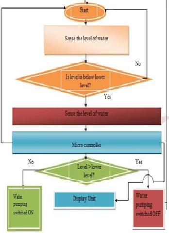
3.Methodology
At the first stage of design a water level
sensor is been made for sensing water level
accurately. Microcontroller is used to
control the overall system automatically that
reduces the design and control complexity.
Microcontroller takes input from the sensor
unit which senses the water level. After
processing input variables, resultant output
decides the water pump’s action (on/off)
with respect to current water status of the
tank. The whole design flow chart is shown
in following (figure 1).When the water is
slowly provided into the tank by keeping the
pump on, the level of water increases in the
tank which is continuously detected by an
ultrasonic sensor and displayed into a LCD
display. When the level reached ultimate
limit then microcontroller switched off the
pump. After that while discharging the
water
at
certain
minimum
level
microcontroller switched on the pump. It
also stored the time of motor of pump being
kept on.
Figure 2. Block diagram of the project
4.Components
The components of the system are as follows:
At mega 8 Microcontroller
Ultrasonic Sonar Sensor
Relay
16×2 LCD Display
Resistor
Variable Resistor
Light Emitting Diode(LED)
Buzzer
3-Terminal 1A Positive Voltage Regulator
Push switch
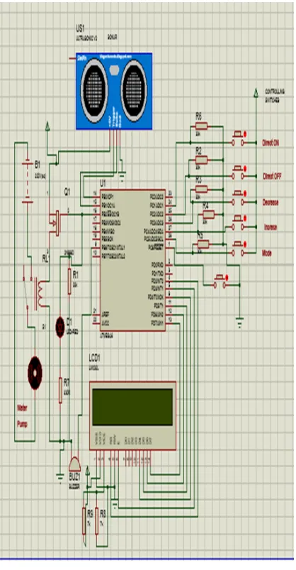
5.Circuit Diagram
In figure 3 the circuit is connected to a power supply of 6 volt DC. Pin PD2, PD3, PD4, PD5, PD6 and PD7 of microcontroller AT mega 8 is connected with LCD via 7KΩ resistor. Pin PC1 is connected with direct ON switch, PC2 is connected with direct OFF switch. Switch with function up, down and mode is connected with PC3, PC4 and PC5 respectively. All the switches are connected with 33KΩ resistor each. Sonar trig pin is connected with PB0 and sonar echo pin is connected with PB1 pin. Pin PB2 is connected with relay via relay driver (MOSFET). To control over the voltage of relay driver a diode is used. Relay is connected with a motor of 220V.
6.Hardware Development and Construction
Figure 3. Circuit diagram of the project
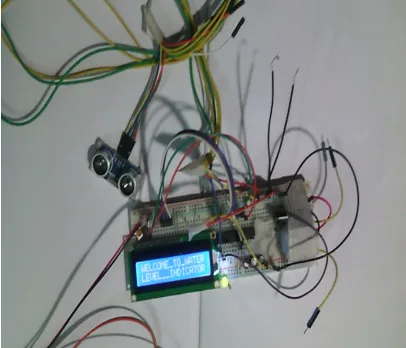
7.Performance Test and Discussion
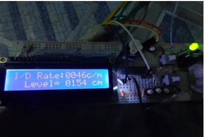
After design And construction the system was tested whether all the connection and whole circuit was working properly or not. The system was assembled with breadboard. To ensure the proper functioning of the components Digital millimeters (DMM) was used. A connection of 6 volt is given. The lower level of water at which pumping is to start is set150 cm and the upper level is set at 190 cm to stop the pump as shown in figure 5 & 6. Initially the level of water was 159 cm which was between 150 cm to 190cm. Which was indicated in display and the condition was also indicated as 'stable' as shown in following figure 7. When The water level reached the value below 150 cm, motor of the pump started rotating indicated by the blipping of LED light (figure 8) and the rate at which the level of water increasing was indicated by the indicator in scale of cm/minute (figure 9). The condition of motor pump was also indicated (figure 10). While reaching the upper level i.e. 190 cm the pump got stopped indicated by shutting the blipping of LED light (figure 11) and the total operating time of water pump was indicated on display (figure 12).
Figure 4. system testing of the project
Figure 5.Setting lower level of water
Figure 6.Setting upper level of water
Figure 7. Indication of water level at 159 cm
Figure 9. starting of pump with Indication of water level
Figure 10. starting of pump with Indication of water level and motor pump condition
Figure 11. Stopping of pump with Indication of water
Figure 12. Stopping of pump with Indication of total
8.
Conclusion
Thus by using this simple arrangement we can save wastage of water and electricity. It is very important for us to control the use of natural resource of energy. By using this circuit we can solve our purpose very easily. Hence we are controlling electric water pump level, controlling through some logics which are described above effectively.. All the inherent parts of the circuit performed consistently. It helped us to come out with good judgment. With the features what it inherits, it seems to be advantageous to the present era. The automatic water level controller has been successfully designed and developed. The sump pump is turned off and on according to the water levels. Compare to other conventional methods, the automatic water level controller shows excellent performance with its reliable digital technology and it is cheaper and durable. The automatic water level controller is a promising controller in terms of system response in water level control with respect to the non linearity introduced by pumps, valves and sensors. Thus the automatic water level controller is a big boon as concerned with the house hold applications as well as other water saving purposes including agricultural sector and industries. Based on the survey result, it is found that the automatic water level controller has a rising demand and it is a good asset from the electronics perspective.
References
[1] http://www.thomasnet.com/articles/instruments-controls/liquid-level-gages.
[2] HAFISA HAMEED, JOMOL T JOSEPH, " STUDY ON WATER LEVEL SENSORS", Water and Land Management Training and Research Institute, Himayatsagar, Hyderabad - 500030..
[3] Gunther Gridling, Bettina Weiss, " Introduction to Microcontrollers ", Vienna University of Technology, Institute of Computer Engineering, Embedded Computing Systems Group, Version 1.
[4] Part of the program is taken from the book - Muhammad Ali Mazidi, Sarmad Naimi, Sepehr Naimi, "The avr microcontroller and embedded system using assembly and c", Pearson Publishers.
[5] ] Melaty Amirruddin., Nurhakimah M. Mukhtar., Hana A. Halim., and Nur S. Noorpi., “Microcontroller Based Water Level Indicator Using GSM Modem: Design and Application”, 1st International Conference on Future Trends in Computing and Communication Technologies, pp.79-83, 2012. [6] Yan Xijun., Lu Limei., and Xu Lizhong.,
Wireless Communications and Trusted Computing, Vol.1, pp.21-24, 2009.
[7] S. M. Khaled Reza., Shah Ahsanuzzaman Md. Tariq., and S.M. Mohsin Reza., “Microcontroller Based Automated Water Level Sensing and Controlling: Design and Implementation Issue”, Proceedings of the World Congress on Engineering and Computer Science, Vol 1, pp.1-7, 2010.