Reduction Of Power Electronic Devices In Multilevel Inverter
For Higher Voltage Level Fed With Induction Motor Drive
Busi Pravallika M Tech Student Scholar
Department of EEE Limat, Krishna (Dt); A.P, India. Email: busipravallika@gmail.com.
A.Sundara Rao Assistant. Professor Department Of EEE Limat, Krishna (Dt); A.P, India.
Email: sundararao276@gmail.com.
SK.Mohiddin HOD Department OF EEE
Limat, Krishna (Dt); A.P, India. Email:shaik36mohiddin@gmail.co
m.
Abstract- In recent years, multilevel inverters have gained much attention in the application areas of medium voltage and high power owing to their various advantages such as lower common mode voltage, lower voltage stress on power switches, lower dv/dt ratio to supply lower harmonic contents in output voltage and current. This paper presents the simulation and implementation of multilevel inverter fed induction motor drive. The output harmonic content is
reduced by using multilevel inverter. The proposed
seven,twenty three,twenty seven and thirty three level cascaded Hbridge multilevel inverters require less number of components to obtain same number of voltage levels when compared to diode clamped and flying capacitor type methods. Due to that, the switching loss gets reduced as same like the harmonic distortion occurs in the motor drive gets reduced. Also, it generally regularizes the stair –case voltage waveform from several dc sources which has reduced harmonic content. The operational principle and key waveforms are analyzed and the performance of the proposed multilevel inverter is evaluated from the simulation results. The results has been compared to that of the existing techniques and found to be quite better than the existing ones.
Keywords: asymmetrical cascaded multilevel inverter, induction motor, pulse width modulation technique, v/f control method, synchronous speed.
I. INTRODUCTION
Multilevel inverter has become more famous over previous years in high power electric applications without the usage of a transformer and filters [1]. Multilevel inverters can be categorized into three topologies, they are, diode-clamped, flying capacitor and cascaded H-bridge cell. The idea of cascaded multilevel inverter is
based on linking Hbridge inverters in series to attain an output of sinusoidal voltage. The output voltage is the sum of the voltage that is produced by each cell. As the number of levels gets increases, the synthesized output waveform has several steps which generate a staircase wave that approaches a preferred waveform [2]. The inverter source voltage generate an output voltage or a current among certain levels either 0 or ±Vdc is called as two-level inverter. Along with that, cascaded Hbridge multilevel inverters have been received an immense attention because of their qualities such as minimum number of components, reliability and modularity. In the
multilevel inverters may well increase the number of output voltage levels. Though, it will require more components resulted in complication and cost increase [3-5].
Multilevel power conversion was first introduced more than two decades ago. This concept explains the utilization higher number of active semiconductor switches to perform the power conversion in small voltage steps. There are several advantages to this approach when compared with the conventional power conversion approach. The smaller voltage steps lead to the production of higher power quality waveforms and also reduce voltage (dv/dt) stress on the load and the electromagnetic compatibility concerns [6]. Another important feature of multilevel converters is that the Semiconductors are connected in series, which allows operation at higher voltages. However, the series connection is typically made with clamping diodes, which eliminates overvoltage concerns. One clear disadvantage of multilevel power conversion is the higher number of semiconductor switches required. However, each active semiconductor added requires associated gate drive circuits and adds further complexity to the converter mechanical layout. Another disadvantage of multilevel power converters is that the small voltage steps are typically produced by isolated voltage sources or a bank of series capacitors [7].
Fig.1.Block diagram of VSI fed Induction Motor.
II. MULTILEVEL INVERTERS
Multilevel inverters have received added awareness for their ability on high-power and medium voltage function and because of former compensation such as high power quality, lower order harmonics, mlTIlmUm switching losses and improved electromagnetic interference [4], [5]. And also multilevel inverters are promising; they have virtually sinusoidal output-voltage waveforms, Output current with improved harmonic profile, a lesser amount of stressing of electronic components owing to decreased voltages, switching losses that are inferior than those of predictable two-level inverters, a slighter filter size, and worse EMI, all of which make them cheaper, lighter, and more compact. Multilevel inverters make small Common mode voltage; consequently the stress in the bearings of a motor allied to a multilevel motor drive can be condensed. In addition CM voltages can be eliminated by using advanced modulation technique. Multilevel inverters can draw input current with low distortion. These inverters can operate at equally fundamental frequency and high switching frequency PWM. It should be noted that lower switching frequency means lower switching loss and higher efficiency. These inverters make a stepped voltage waveform by means of a number of dc voltage sources as the input and a suitable arrangement of the power-semiconductor-based devices [6]. Three major structures of the multilevel inverters have been presented: "diode clamped multilevel inverter," "flying capacitor multilevel inverter," and "cascaded multilevel inverter" [7]. The cascaded multilevel inverter is collected of a number of single-phase H-bridge inverters and is classified into symmetric and asymmetric groups based on the magnitude of dc voltage sources. In the symmetric types, all the dc voltage sources of cascaded H-bridges are having equal magnitudes, whereas in the asymmetric types, the values of the dc voltage sources of all Hbridges are dissimilar. In topical years, a number of topologies with various control techniques have been presented for cascaded multilevel inverters [8]-[9]. In [7] and, diverse symmetric cascaded multilevel inverters have been presented. The foremost advantage of all these structures is the short variety of dc voltage sources, which is one of the most significant features in determining the cost of the inverter. On the other hand, because some of them utilize an elevated number of bidirectional power switches, a high number of insulated gate bipolar transistors (IGBTs) are necessary, which is the major drawback of these topologies. Consequently, it
increases control complexity, circuit size and cost. The major advantage of this asymmetric topology and its algorithms is associated to its ability to create a substantial number of output voltage levels by using a low number of dc voltage sources and power switches but the high diversity in the magnitude of dc voltage sources is their most outstanding disadvantage.
Recently, asymmetrical and hybrid multistage topologies are becoming one of the most fascinated research area. In the asymmetrical configurations, the magnitudes of dc voltage supplies are uneven. These topologies diminish the cost and size of the inverter and get better reliability since lesser number of power electronic components, capacitors, and dc supplies are used. The hybrid multistage converters consist of dissimilar multilevel configurations with uneven dc voltage supplies. Bidirectional switches with an suitable control technique can enhance the performance of multilevel inverters in terms of falling the number of semiconductor components, minimizing the withstanding voltage and achieving the required output voltage with higher levels [10]-[11]. The magnitudes of the utilized dc voltage supplies have been selected in a way that brings the elevated number of voltage levels with an effective application of a fundamental frequency staircase modulation technique. For a single-phase seven-level inverter, 12 power electronic switches are required in both the diode-clamped and the flying-capacitor topologies. Asymmetric voltage technology is used in the cascade H-bridge multilevel inverter to allow more levels of output voltage [12], so the cascade Hbridge multilevel inverter is suitable for applications with increased voltage levels. Two Hbridge inverters with a dc bus voltage of multiple relationships can be connected in cascade to produce a single phase seven-level inverter and eight power electronic switches are used. In this paper a new asymmetric Bi-directional converter topology which uses contradictory ratios of dc voltage sources.
III. PROPOSED CONCEPT
Hybrid Multilevel Inverter was introduced by means of all 3M possible output voltages, where M is the number of modules allied in series. Though this inverter uses extremely different DC voltage sources in the relation of 1:3:9 etc. In distinguish, the DC voltage sources consider in this paper are still exceptionally close to each other, they fluctuate only by ±20 %. The quantity of cells in sequence determines the number of output levels. 3M= 27 switching states SI ,when M= 3 cells. With similar DC voltages, there are numerous switching states that create the same output voltages, resulting in 2.M + 1 = 7 different phase output voltage levels. Uneven DC source voltages direct to an improved number of different output voltage levels. The maximum number of levels is 3M = 27. With
levels are consistently spaced. The aim of such an inverter (Hybrid Multilevel Inverter) has the disadvantage that the preliminary modularity is vanished. Each module must be intended for the equivalent voltage class. When the DC source voltages are uneven but only ±20 % unlike from each other, the number of different output voltage levels is also superior. As an instance, we believe a case where one cell has 100 % of its nominal DC voltage, other has 120% and the third one has 80%. The DC source voltages are in relation of 4:5:6 in this scheme. As can be seen, the voltage levels are approximately the same as in the 1:3:9 case, apart from some levels not there at high complete values of output voltage. In order to consider the possible benefits of using unlike DC voltages, the 4:5:6 relation is used as an instance in the following part. For a first estimation it is abandoned if these differences are introduced by the moment behaviour of the DC voltages, or if they are introduced by design and thus can be supposed to be stable. The second case is considered at this time for the sake of simplicity. The below figure shows the output wave forms the proposed asymmetrical converter. It is clearly seen that the level of inverter varies with the change in the ratios of input voltage. The inverter gives 7 level output voltage when the ratio is 1: 1:1, while it gives 23 level output voltage when the ratio is 4:5:6 and it gives 27 level output voltage when the ratio is I :3:9. This inverter having 3 bridges connected in series gives different levels of output voltages without changing the circuit except the ratios of input voltages. Switching of the converter is done by following the staircase control technique. Pulse width Modulation technique can also be applied by appropriate calculation of the switching time period.
a) 1:1:1
(b).4:5:6
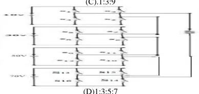
(C).1:3:9
(D)1:3:5:7
Fig. 2. Proposed asymmetrical cascaded multilevel inverter with different voltage ratios.
IV. CONTROL SCHEME
This section will discuss in detail a converter consisting of three modules with a DC voltage ratio of Vi11:Vi12:Vi13 = 4Voc : 5Voc : 6Voc. As can be seen in Fig. 3, this results in a huge number of diverse output voltage levels with an incredibly good voltage resolution. This composition will be compared with the predictable approach with identical DC voltage sources, and with the Hybrid Multilevel Inverter using a 1:3:9 voltage relation. Two different control methods for a single phase converter are offered. Both algorithms imagine a steady sampling interval of the control, Ts. The first one uses a stable switching state during a full sampling interval (step or staircase method), whereas the second one is implemented with a Pulse Width Modulation (PWM method). Both methods receive that the DC source voltages are not steady but variable in time. The definite voltages on the capacitors are therefore calculated, and the phase voltage vector Vii is created. In order to compute all attainable output voltages Vol, the phase voltage vector is multiplied with all 311 possible switching states SI. This results in an unsorted vector containing all feasible output voltages.
Fig.3.output voltages of different voltage ratios of CHB. Table I. Switching Sequence of 23-Level CHB
Table II. Switching Sequnce Of 27-Level CHB Inverter
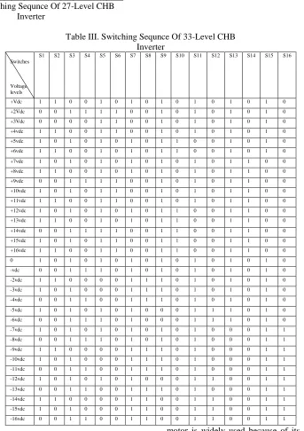
Table III. Switching Sequnce Of 33-Level CHB Inverter
Switches
Voltage levels
S1 S2 S3 S4 S5 S6 S7 S8 S9 S10 S11 S12 S13 S14 S15 S16
+Vdc 1 1 0 0 1 0 1 0 1 0 1 0 1 0 1 0
+2Vdc 0 0 1 1 1 1 0 0 1 0 1 0 1 0 1 0
+3Vdc 0 0 0 0 1 1 0 0 1 0 1 0 1 0 1 0
+4vdc 1 1 0 0 1 1 0 0 1 0 1 0 1 0 1 0
+5vdc 1 0 1 0 1 0 1 0 1 1 0 0 1 0 1 0
+6vdc 1 1 0 0 1 0 1 0 1 1 0 0 1 0 1 0
+7vdc 1 0 1 0 1 0 1 0 1 0 1 0 1 1 0 0
+8vdc 1 1 0 0 1 0 1 0 1 0 1 0 1 1 0 0
+9vdc 0 0 1 1 1 1 0 0 1 0 1 0 1 1 0 0
+10vdc 1 0 1 0 1 1 0 0 1 0 1 0 1 1 0 0
+11vdc 1 1 0 0 1 1 0 0 1 0 1 0 1 1 0 0
+12vdc 1 0 1 0 1 0 1 0 1 1 0 0 1 1 0 0
+13vdc 1 1 0 0 1 0 1 0 1 1 0 0 1 1 0 0
+14vdc 0 0 1 1 1 1 0 0 1 1 0 0 1 1 0 0
+15vdc 1 0 1 0 1 1 0 0 1 1 0 0 1 1 0 0
+16vdc 1 1 0 0 1 1 0 0 1 1 0 0 1 1 0 0
0 1 0 1 0 1 0 1 0 1 0 1 0 1 0 1 0
-vdc 0 0 1 1 1 0 1 0 1 0 1 0 1 0 1 0
-2vdc 1 1 0 0 0 0 1 1 1 0 1 0 1 0 1 0
-3vdc 1 0 1 0 0 0 1 1 1 0 1 0 1 0 1 0
-4vdc 0 0 1 1 0 0 1 1 1 0 1 0 1 0 1 0
-5vdc 1 0 1 0 1 0 1 0 0 0 1 1 1 0 1 0
-6vdc 0 0 1 1 1 0 1 0 0 0 1 1 1 0 1 0
-7vdc 1 0 1 0 1 0 1 0 1 0 1 0 0 0 1 1
-8vdc 0 0 1 1 1 0 1 0 1 0 1 0 0 0 1 1
-9vdc 1 1 0 0 0 0 1 1 1 0 1 0 0 0 1 1
-10vdc 1 0 1 0 0 0 1 1 1 0 1 0 0 0 1 1
-11vdc 0 0 1 1 0 0 1 1 1 0 1 0 0 0 1 1
-12vdc 1 0 1 0 1 0 1 0 0 0 1 1 0 0 1 1
-13vdc 0 0 1 1 0 0 1 1 1 0 1 0 0 0 1 1
-14vdc 1 1 0 0 0 0 1 1 0 0 1 1 0 0 1 1
-15vdc 1 0 1 0 0 0 1 1 0 0 1 1 0 0 1 1
-16vdc 0 0 1 1 0 0 1 1 0 0 1 1 0 0 1 1
V. INDUCTION MOTOR (IM)
An induction motor is an example of asynchronous AC machine, which consists of a stator and a rotor. This
due to this field, which creates another field that tries to align with the stator field, causing the rotor to spin. A slip is created between these fields, when a load is applied to the motor. Compared to the synchronous speed, the rotor speed decreases, at higher slip values. The frequency of the stator voltage controls the synchronous speed. The frequency of the voltage is applied to the stator through power electronic devices, which allows the control of the speed of the motor. The research is using techniques, which implement a constant voltage to frequency ratio. Finally, the torque begins to fall when the motor reaches the synchronous speed. Thus, induction motor synchronous speed is defined by following equation,
Where f is the frequency of AC supply, n, is the speed of rotor; p is the number of poles per phase of the motor. By varying the frequency of control circuit through AC supply, the rotor speed will change.
A. Control Strategy of Induction Motor
Power electronics interface such as three-phase SPWM inverter using constant closed loop Volts l Hertz control scheme is used to control the motor. According to the desired output speed, the amplitude and frequency of the reference (sinusoidal) signals will change. In order to maintain constant magnetic flux in the motor, the ratio of the voltage amplitude to voltage frequency will be kept constant. Hence a closed loop Proportional Integral (PI) controller is implemented to regulate the motor speed to the desired set point. The closed loop speed control is characterized by the measurement of the actual motor speed, which is compared to the reference speed while the error signal is generated. The magnitude and polarity of the error signal correspond to the difference between the actual and required speed. The PI controller generates the corrected motor stator frequency to compensate for the error, based on the speed error.
VI.MATLAB/SIMULATION RESULTS
Fig.4. Proposed asymmetrical cascaded multilevel inverter.
Fig.5. Output voltage wave form of 7-level inverter.
Fig.6.THD of the cascaded 7-level inverter.
Fig.7. Output voltage wave form of 23-level inverter
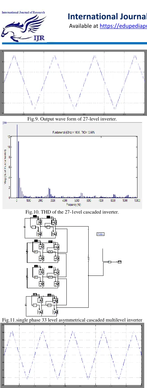
Fig.9. Output wave form of 27-level inverter.
Fig.10. THD of the 27-1evel cascaded inverter.
Fig.11.single phase 33 level asymmetrical cascaded multilevel inverter
Fig.12. Output voltage wave form of single phase 33-level inverter.
Fig.13.THD of the 33-1evel cascaded inverter.
Figure.14.Matlab/Simulink Model of Proposed 33 Level Multilevel Inverter Applied to Induction Machine Drive.
Figure 14 shows the Mat lab/Simulink Model of Proposed 33 level Multilevel Inverter Applied to Induction Machine Drive using Matlab/Simulink platform.
Fig.15.Three Phase Output Voltage of 33 level inverter.
Figure.16.Stator Currents, Speed and Torque Characteristics of Induction Fed Motor.
VII.CONCLUSIONS
being increased the structure of the output waveform is increased. In spite of the improvement in the output voltage waveform the results obtained from the motor gave surprising results. The stator currents of the motor which must be sinusoidal are approaching near to a sine wave as the number of level is increasing. A comparative analysis on THD (total harmonic distortion) is done and for a seven level inverter it is 30% and for a 23 level inverter it is 23.51% and for 27 level inverter it is 12.56% and 33 level inverter it is 12.36%.One thing to be remembered is even though the levels are increased the inverter structure is not being changed and it remains as same and this the advantage of the proposed structure which can produce multiple outputs.
REFERENCES
[1] “Asymmetrical Multilevel Inverter for Higher Output Voltage Levels”
[2] 1. A Santiago-Gonzalez, 1.Cruz-Colon, R. otero-De-leon, V. lopezSantiago, E.I. Ortiz-Rivera, " Three phase induction motor drive using fly back converter and PWM inverter fed from a single photovoltaic panel," Proc. IEEE PES General Meeting, pp. 1-6,20II. [3] M. A Vitorino et aI. , "An efficient induction motor control for photovoltaic pumping," IEEE Trans. Industrial Electron., vol. 54, no.4, pp. 1162-1170, April. 2011.
[4] ADiaz, R. Saltares, C. Rodriguez, R. F. Nunez, E.!. OrtizRivera, and 1. Gonzalez-Llorente, "Induction motor equivalent circuit for dynamic simulation," Proc. IEEE Electric Machines and Drive Conference, (lEMDC ), May 2009.
[5] E. Babaei and S. H. Hosseini, "Charge balance control methods for asymmetrical cascade multilevel converters," in Proc. ICEMS, Seoul, Korea, 2007, pp. 74-79.
[6] K. Wang, Y. Li, Z. Zheng, and L. Xu, "Voltage balancing and fluctuation suppression methods of floating capacitors in a new modular multilevel converter," IEEE Trans. Ind. Electron., vol. 60, no. 5, pp. 1943-1954, May 2013.
[7]L.M Tolbert, F. Z.Peng and T.G Habelter, "Multilevel Converter for large electric drives," IEEE trans.lnd.Appl.VoI35, no.I, pp. 36-44, Jan/Feb.1999.
[8].K. Nakata, K. Nakamura, S. lto and K. Jinbo, "A three level traction inverter with IGBTs for EMU", in Conf.Rec. IEEE lAS Annu.meeting, 1994, voU, pp. 667- 672.
[9].AJidin,N.R, N.R, N.R. N. ldris, AH.M. Yatim, t. Sutikno and E.Elbuluk,"An optimized switching strategy for quick dynamic torque control in DTC-hysteresis-based induction machines, , .IEEE trans. lnd.Electron. vo1.58, no.8,pp 33913400,Aug. 2011.
[10] E. Babaei, "A new cascaded multilevel inverter topology with minimum switches," IEEE Trans. PowerElectron. Vol 23, no.6, pp. 2657- 2664, Nov. 2008.
[11] E. A Mahrouset al., "Three-phase three-level voltage source inverter with low switching frequency based on the two level inverter topology," Electr.Power Appl., vol. I, pp. 637- 641, 2007.
MS.B.PRAVALLIKA is a student of EEE department in Lingayas Institute of Management And Technology In Madalavarigudem Vijayawada .she is presently pursuing her M.Tech degree from JNTU Kakinada. She has obtained B.Tech degree from Amrita Sai Institite of Science and Technology Paritala. Jntu Kakinada
Mr.A.SUNDARRAO is presently working as Assistant professor in EEE department in Lingayas Institute of Management And Technology Madalavarigudem. He has obtained his B.Tech degree from Lakireddy Balireddy College of Engineering mylavaram. From JNTUK. And M.Tech degree from Gudlavalleru Engineering College Krishna District. He has published research papers in national and international journals.